SOLA SE Light Engine Instruction Manual - Lumencor
←
→
Transcription du contenu de la page
Si votre navigateur ne rend pas la page correctement, lisez s'il vous plaît le contenu de la page ci-dessous
SOLA SE Light Engine ®
  Instruction Manual

Lumencor, Inc.   Document Number 57-10002   www.lumencor.com
!
Regulatory Models
Lumencor utilizes regulatory model names for all certified and CE marked products. The regulatory model names
are traceable to all regulatory documentation, third party reports and certifications.

“Regulatory Model: Sola” is used as a representative model for all certified and CE marked Sola Products.

Emissions
This equipment has been tested and found to comply with the limits of EMC directive 2014/30/EU. These limits are
designed to provide reasonable protection against harmful interference when the equipment is operated in a com-
mercial environment. This equipment generates, uses, and can radiate radio frequency energy and, if not installed
and used in accordance with the instruction manual, may cause harmful interference to radio communications.

Safety Certifications
TUV SUD America, CB Certification (IEC 61010-1:2010)
TUV SUD America, NRTLus Certification (UL 61010-1:2012-05)
TUV SUD America, cNRTL Certification (CAN/CSA-C22.2 No. 61010-1:2012)
TUV SUD America, EN Certification (EN 61010-1:2010)

CE Marking
Low Voltage Directive (2014/35/EU)
EMC Directive (2014/30/EU)
RoHS Directive (2011/65/EU)
REACH Regulation (EC) No. (1907/2006/EC)

EU Declarations of Conformity and China RoHS hazardous substance tables can be found at http://lumencor.com/
company/regulatory-compliance/

Lumencor, Inc.
14940 NW Greenbrier Parkway
Beaverton, OR 97006

T 503.213.4269

www.lumencor.com

Document Number 57-10002

072018

    SOLA SE Light Engine Instruction Manual                                                                         !1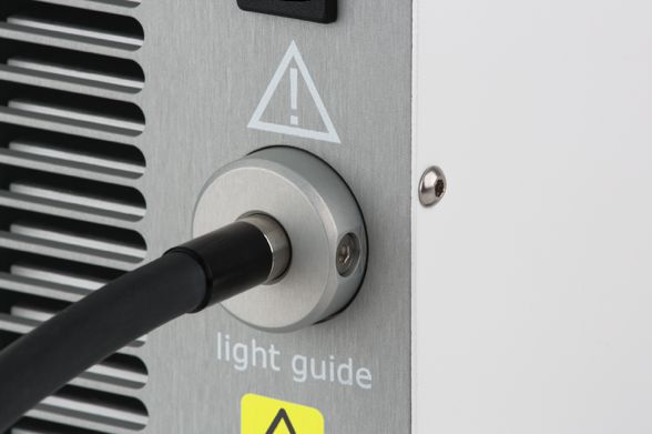
!

Table of Contents
1. Introduction
2. Precautions and Warnings
3. Installation and Operating Instructions
4. Spectral Output
5. Product Specifications
6. Routine Maintenance and Troubleshooting
7. Customer Support
8. Warranty

  SOLA SE Light Engine Instruction Manual        !2
!

1. Introduction
Lumencor’s SOLA SE light engines are designed for laboratory use by bioanalytical researchers and/or developers of
life science instrumentation. SOLA SE light engines generate white light output by combining the outputs of five
solid state light sources. The on/off status and intensity of the white light output is electronically controlled via serial
commands from a USB-connected computer workstation or a controller pod accessory (part number 83-10007).
On/off status can also be controlled manually via a rocker switch located on the front panel or a foot switch
accessory (part number 29-10045) that plugs into the 3.5 mm connector on the rear panel. This manual covers
SOLA SE, SOLA SE 365, SOLA SE V–nIR and SOLA SE U–nIR light engine models, which are defined in the table
below.

                                                                                                                SOLA SE U–nIR
                                                                                                SOLA SE V–nIR
                                                                                  SOLA SE 365
                          SOLA SE light engines

                                                                        SOLA SE
                           PRODUCT MATRIX

                   Manual control                                     ✔           ✔             ✔               ✔
                   Electronic control                                 ✔           ✔             ✔               ✔
                   365 nm ultraviolet source                                      ✔                             ✔
                   395 nm violet source                               ✔                         ✔
                   735 nm near-IR source                                                        ✔               ✔
                   4 visible sources 420–680 nm                       ✔           ✔             ✔               ✔
                   nmnmnmnmnmnm65065680 nm nm

2. Precautions and Warnings {Précautions et mises en garde}
A few simple practices will ensure trouble-free operation for the life of the light engine.

Les quelques règles simples suivantes permettront d’assurer un fonctionnement fiable pendant toute la durée de
service de la source lumineuse.

Safety Instructions:
Please read and follow all safety instructions provided BEFORE using your new SOLA SE light engine. Failure to
comply with the safety instructions may result in fire, electrical shock, or personal injury and may damage or impair
protection provided by equipment. Please save all safety instructions.

Instructions de sécurité:
Veiller à lire et à respecter toutes les instructions de sécurité fournies AVANT d’utiliser le nouveau SOLA SE afin
d’écarter les risques d’incendie, de décharge électrique, de blessure corporelle et de possibles dommages ou dé-
faillance de la protection offerte par l’appareil. Conserver toutes les instructions de sécurité.

Safety Definitions {Définitions relatives à la sécurité}:

             Warning: Statements identify conditions or practices that could result in personal injury.

     SOLA SE Light Engine Instruction Manual                                                                                        !3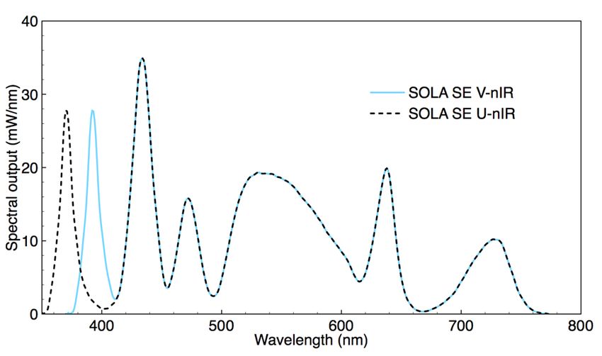
!
Avertissement: déclarations qui identifient des situations ou des pratiques susceptibles d’entraîner des blessures
corporelles.

Caution: Statements identify conditions or practices that could result in damage to your equipment.

Attention: déclarations qui identifient des situations ou des pratiques susceptibles d’endommager le matériel.

Safety Items {Mesures de sécurité}:

Warning: DO NOT use an unapproved power supply. The Lumencor-supplied external power supply is
recommended for use with the SOLA SE light engine. Alternative 24 V DC power supplies may be used provided
that the current is limited to 5.0 A max. Also, it is imperative that the alternative power supply has output over-
current protection, as the power input of the SOLA SE is not fused. The equipment is required to be supplied by a
properly approved/certified DC power source meeting the minimum electrical ratings of the product. Connect the AC
power cord to a receptacle with a protective safety (earth) ground terminal.

Avertissement : NE PAS utiliser une alimentation électrique non homologuée. Il est conseillé d’utiliser
l’alimentation électrique externe fournie par Lumencor avec la source lumineuse SOLA SE. Il est possible d’utiliser
une autre alimentation électrique continue 24 V à condition que l’intensité soit limitée à 5,0 A maximum. En outre, il
est impératif qu’elle présente une protection de sortie contre les surintensités, car l’entrée d’alimentation du SOLA
SE ne comporte pas de fusible. L'équipement doit être fourni par un / certifié DC réunion de source d'alimentation
correctement approuvé les ratings électriques minimales du produit. Brancher le cordon électrique sur une prise de
courant protégée par une borne de terre.

Warning: DO NOT look into the output of the light engine. The brightness of this light source is higher than
most commercial lighting fixtures and is required to couple directly into a microscope or other bioanalytjcal
instrument.

Avertissement: NE PAS regarde directement la sortie de la source lumineuse. L’intensité lumineuse de cette
source est supérieure à celle de la majorité des appareils d’éclairage disponibles dans le commerce et est conçue
pour un raccordement direct à un microscope ou autre appareil de bioanalyse.

Warning: DO NOT turn on the light unless the output end of the light guide is safely directed into an en-
closed optical path. DO NOT point the light output directly onto any flammable or burn-susceptible materi-
al. This includes all animal or vegetable tissues, plastics, fabrics, paper and liquids.

Avertissement: NE PAS allumer la lumière sans l'extrémité de sortie du guide de lumière dirigée en toute
sécurité dans un chemin optique fermé. NE PAS pointer la sortie de lumière directement sur un matériau sus-
ceptible d'être inflammable ou susceptible de brûler. Cela comprend tous les tissus, les plastiques, les tissus, le pa-
pier et les liquides animaux ou végétaux.

    SOLA SE Light Engine Instruction Manual                                                                              !4
!
RISK GROUP 3
Warning: Possibly hazardous optical radiation emitted from this product. Do not look at operating lamp. Eye injury
may result.
Warning: Infrared (IR) emitted from this product. Do not look at operating lamp.
Warning: UV emitted from this product. Avoid eye and skin exposure to unshielded product.
GROUPE DE RISQUE 3
Avertissement: Rayonnement optique peut-être dangereux émis par ce produit. Ne regardez pas la lampe d'ex-
ploitation. Une blessure oculaire peut entraîner.
Avertissement: Infrarouge (IR) émise par ce produit. Ne regardez pas la lampe d’exploitation.
Avertissement: UV émis par ce produit. Évitez les yeux et la peau exposition au produit non blindé.
Caution: DO NOT open the unit. There are no serviceable parts inside and opening the light engine enclosure will
void the manufacturer’s warranty.
Attention: NE PAS ouvrir l’appareil. Il ne contient aucune pièce réparable et l’ouverture de son boîtier a pour effet
d’annuler la garantie.
Caution: DO NOT set liquids on the light engine. Spilled liquids may damage your light engine.
Attention: NE PAS placer de liquide sur la source lumineuse. Les liquides renversés peuvent endommager la
source lumineuse.
Caution: DO NOT drop the light engine. It contains glass optical components that could be damaged or mis-
aligned by the shock produced by a drop onto a hard surface.
Attention: NE PAS laisser tomber la source lumineuse. Elle contient des composants optiques en verre sus-
ceptibles d’être endommagés ou désalignés par le choc résultant d’une chute sur une surface dure.
DISCLAIMER: Lumencor shall not be liable for injury to the user or damage to the product resulting from
the SOLA SE light engine being used in a way for which it was not intended and in complete disregard
for all posted safety precautions and warnings.
AVIS DE NON-RESPONSABILITÉ: Lumencor décline toute responsabilité pour les blessures corporelles
ou les dommages au produit résultant d’une utilisation du SOLA SE autre que celle prévue et du mépris
total de toutes les mesures de sécurité et mises en garde affichées.
SOLA SE Light Engine Instruction Manual !5!
3. Operating Instructions
AC Power Cords
3.1 Contents
The SOLA SE light engine ships with the following list of standard components: Region Part Number
1. SOLA SE light engine configured with an output adapter for coupling to a North America 29-10002
3 mm diameter liquid light guide. Europe 29-10005
2. A 24 V /5 A DC power supply (Lumencor part number 27-10001). United Kingdom 29-10004
3. A region-specific 6 ft AC power cord for the power supply (see adjacent
Israel 29-10008
table).
Australia/New Zealand 29-10024
4. A 6 ft USB A (M) to USB (B) M cable (29-10058) for serial connection to a
light engine control pod or host computer.
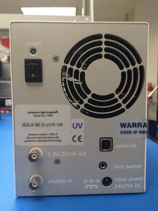
The model name and unique 4- or 5- digit serial
number of the light engine are marked on a label
affixed to the back panel (Figure 1). SOLA SE 365
and SOLA SE U–nIR light engines are identified by a
UV marking on the rear panel (Figure 1).
Performance specifications for individual light engines
are listed on the certificate of conformance included
with the shipping documents e-mailed to the
customer. It is important to retain the certificate of
conformance for reference. In the event that the light
engine is sold or transferred, the certificate of
conformance should be conveyed to the new owner.
3.2 Installation
When setting up the SOLA SE light engine for use, be
sure to place the unit on a hard surface and avoid
blocking or restricting airflow at the air intake (front
panel) and exhaust port (rear panel, Figure 1).
Restricting the airflow will cause the unit to operate at
elevated temperatures and will result in decreased
product life and/or premature failure.
Position the unit in an orientation that allows
unrestricted access to the DC power connector at
the back of the light engine. In an emergency, you
may need to disconnect power to the unit quickly.
The rocker switch in the top left corner of the rear Figure 1. Model and serial number identification label on the
panel controls electrical power to the unit. A green SOLA SE 365 light engine rear panel.
LED above the switch indicates that power to the light engine is ON. Refer to Figure 1 for the rear panel locations of
the input DC power connection, the foot pedal connection and the master electrical power switch. Note that the
foot pedal is an on/off toggle switch. Its on/off status cannot be determined from its position. Before connecting
the foot pedal, make sure the electrical power switch (Figure 1) is in the OFF position to avoid unintentional initiation
of light output. After connecting the foot pedal, and with the light guide output safely directed into an enclosed
optical path (e.g. microscope input collimator or a beam dump), turn the power switch ON to begin operation.
SOLA SE Light Engine Instruction Manual !6!
The SOLA SE light engine has a safety interlock for the light
guide that prevents light output unless a liquid light guide is
fully inserted into the light guide port. Before operating the
unit, make sure the 3 mm diameter liquid light guide is properly
installed in the light guide port (Figure 2). The set screw
should be loosened using a 2 mm hex wrench so the light
guide slides all the way into the receptacle without obstruction.
Once the light guide is fully inserted, lightly tighten the set
screw to hold it in place and prevent inadvertent
disconnection. Prior to turning the light on, be sure the output
end of the light guide is safely directed into an enclosed optical
path (e.g. microscope input collimator or a beam dump). Do
not bend the light guide beyond its specified minimum
bending radius (40 mm or 1.6 inches). Extreme bending of
the light guide may cause permanent deformation, resulting in Figure 2. 3 mm diameter liquid light guide inserted
decreased light transmission. In the event that the light guide in front panel light output port.
is retracted from the output port during operation, light output
will cease immediately. To restart light output: 1) turn the
electrical power switch (Figure 1) off, 2) fully insert and secure the light guide in the output port (Figure 2), 3) turn the
electrical power switch back on, and then 4) activate light output using the front panel rocker switch, foot pedal or
serial control device (control pod or computer workstation). Take necessary precautions to protect yourself
and others from the high intensity light when turning on the unit.
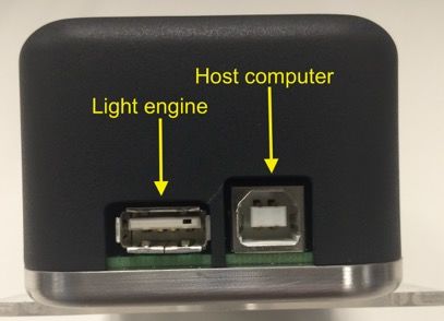
3.3 Operation Using Light Engine Control Pod
1. Connect the USB A port of the light engine control
pod accessory (Figure 3) to the USB B port on the
SOLA SE (“external”. Figure 1) using the USB A-to-
USB B cable (29-10058) [1]. For pass-through
control from a computer workstation, connect the
USB B port of the control pod to a USB A port on
the host computer.
2. The manual light output switch above the light output
port on the front panel of the SOLA SE should be in
the off (o) position. This is necessary to avoid
manual override of serial on/off commands from the
pod.
3. Press and hold the right button on the pod until a Figure 3. USB connectors on the rear of
menu of light engines appears. Turn the rotary dial to the light engine control pod.
select “SOLA SE” from the menu. Press the right
button again to return to the main (0–100 analog intensity) display screen.
4. Before turning the light output on, be sure the output end of the light guide is safely directed into an
enclosed optical path (e.g. microscope input collimator or a beam dump).
5. Press the right button to turn the light output on. An amber indicator LED above the manual light output
switch on the SOLA SE front panel indicates active light output. Adjust the output intensity using the rotary
dial [3,4]. Press the right button again to turn the light output off [2].
SOLA SE Light Engine Instruction Manual !7!
6. Press and hold the left button to view a digital rendition of the intensity setting [5]. Press the right button
to return to the main display screen.
7. Serial commands sent from a host computer to the USB B port of the control pod will automatically switch
the pod from local to pass-through mode, indicated by the message “PC pass through mode active”
shown on the pod display screen. Local command mode is disabled as long as pass-through mode
remains active.
8. To quit pass-through mode and return to local command mode, press the right button on the pod twice.
9. Further details of control pod operation are provided in a downloadable instruction sheet.
Notes
[1] This connection supplies electrical power to the pod from the SOLA SE. The pod will turn on when the
connection is made.
[2] There is no warm-up time; the light engine output stabilizes less than 1 second after the light output is
switched on. Light output can be switched off during intervals when it is not required for active viewing or data
collection. After light output is switched off, the cooling fan will continue to run for 5 minutes, after which it will
automatically stop until light output is turned back on.
[3] Output intensity can be set from 0–100% in 1% increments; however operation in the 0–5% range is not
recommended.
[4] Dialing intensity to zero automatically issues an OFF command to the light engine. Press the right button
to turn the light output on again.
[5] The current intensity settings are internally stored. When the pod is powered down, the settings are
retained and will be restored at the next restart.
3.4 Operation Using Computer Workstation
1. Although the following instructions specify Lumencor’s SOLA GUI, operations using third-party image
acquisition control software providing co-ordinated operation of the light engine with cameras and other
peripherals are generally similar.
2. Operation and installation of the SOLA GUI requires a computer running the Windows operating system
with a free USB port.
3. Download the zip file for the SOLA GUI INSTALLER from http://lumencor.com/resources/documentation-
software/.
4. Unzip the file and run setup.exe to install the SOLA GUI.
5. Connect the USB A-to-USB B cable between the computer and the USB B B (external) port on the SOLA
(Figure 1).
6. Successful installation is indicated by the appearance of “USB Serial Port (COM #)” under the “Ports (COM
&LPT)” tab in the Windows Device Manager. If the virtual COM port (VCP) is not registered by the
operating system, download and install the VCP driver from http://lumencor.com/resources/
documentation-software/.
7. Connect the DC power supply to the SOLA.
8. Check that the liquid light guide is fully inserted and locked in the front panel receptacle (Figure 2) and that
the output end is safely directed into an enclosed optical path (e.g. microscope input collimator or a beam
dump).
9. Toggle the power switch on the rear panel to the ON position. The green LED above the switch (Figure 1)
should light.
SOLA SE Light Engine Instruction Manual !8!
10. The manual light output switch above the light output port on the front panel of the SOLA SE should be in
the off (o) position. This is necessary to avoid manual override of serial on/off commands from the
computer.
11. Run the GUI by going to the Program Menu and selecting LLE SOLA SE-2 Controller.
12. In the COM pulldown menu (GUI window, upper left), select COM # assigned to USB-Serial port.
13. Press the “INIT” button in the GUI
14. The computer should now have control of the SOLA. In the GUI window, the ON-OFF button below the
intensity slider turns light output on or off. An amber indicator LED above the manual light output switch
on the SOLA SE front panel indicates active light output. The graduated slider in the GUI window controls
the source output intensity [1,2].
15. There is no warm-up time; the light engine output stabilizes less than 1 second after the light output is
switched on. Light output can be switched off during intervals when it is not required for active viewing or
data collection. After light output is switched off, the cooling fan will continue to run for 5 minutes, after
which it will automatically stop until light output is turned back on.
Notes
[1] Output intensity can be set from 0–255; however operation in the range 0–13 (0–5%) is not recommended.
[2] Setting the intensity slider to zero is not functionally equivalent to turning light output off using the ON-OFF
button. In this condition, the fan will continue to run as the light sources are still energized, even though their output
may not be detectable.
3.5 Using the Electronic Shutter Function
The SOLA SE light engine output can be selectively enabled and disabled using TTL levels applied to the BNC
connector marked “shutter in” on the rear panel (Figure 1). A > 3.3 V “high” signal applied to the BNC connector will
enable white light output, while a!
4. Spectral Output
Typical output spectral distributions of SE V-nIR and SOLA SE U-nIR light engines are shown below (Figure 4).
Figure 4. SOLA SE V-nIR and SOLA SE U-nIR light engine spectral output distributions.
5. Product Specifications
SOLA SE light engines must be operated and stored within the environmental conditions specified in the table on
page 11. Performance specifications for individual light engines are listed on the certificate of conformance included
with the shipping documents e-mailed to the customer. It is important to retain the certificate of conformance for
reference. In the event that the light engine is sold or transferred, the certificate of conformance should be conveyed
to the new owner. Certificates of conformance are also recorded in Lumencor’s database and copies can be
requested by e-mail to techsupport@lumencor.com. The request message must include the 4- or 5- digit serial
number of the light engine.
SOLA SE Light Engine Instruction Manual !10!
Specification Detail
Temperature
Operating 32 to 95° F (0 to 35° C)
Non-operating -4 to 158° F (-20 to 70° C)
Humidity
Operating and non-operating 0 to 80% relative humidity, non-condensing
Altitude
Operating 0 to 10,000 feet (3,048 meters)
Non-operating 0 to 45,000 feet (13,176 meters)
Dimensions (WxLxH) 12.5 cm x 26.3 cm x 16.3 cm (4.90 in x 10.4 in x 6.40 in)
Weight 8.0 lb / 3.6 kg
Input Power Requirements 24 V DC / 5.0 A, 120 W maximum, power supply included
Power consumption 90 W (light output on at 100%); 3 W (light output off, fan on)
Warm-up Period 1s
Electronic Shutter On/Off rate up to 1 kHz
Protection IP Rating of X0
Sound Level Sound Level at 1 m < 10 db(A)
3.5 mm foot switch (optional accessory), USB B for serial connection to
Connections controller pod or host computer, two BNC connections for (1) TTL
electronic shutter input and (2) 3.3V DC /25 mA power output.
Warranty 36 months parts and labor
6. Routine Maintenance and Troubleshooting
No routine maintenance is required. There are no user-replaceable components or sub-assemblies in the SOLA SE
light engine. Opening the light engine enclosure will void the manufacturer’s warranty. In the event that the light
engine fails to perform in accordance with the specifications listed on the certificate of conformance, review the
troubleshooting procedures on page 12. If the problem remains unresolved, please contact Lumencor Technical
Support for assistance, as directed in Section 7.
SOLA SE Light Engine Instruction Manual !11!
SOLA SE Light Engine Troubleshooting
Problem Check the following
Green power indicator does not Check that the liquid light guide is fully inserted in the front panel
light up when the master power receptacle and is secured by the set screw.
switch is in the ON position
Light engine does not respond to Check that the manual light output switch on the front panel is in the OFF
light on/off commands from the position.
control pod or PC
Unusually weak fluorescence Weak fluorescence in all detection channels (DAPI, FITC, TRITC, Cy5 etc)
signals across all detection is likely to be due to poor light transmission by the liquid light guide, the
channels collimating adaptor or another distal component of the microscope
optical path and not to abnormally low light output from the SOLA SE
light engine.
Unusually weak fluorescence Check that the filter cube in the microscope is compatible with the output
signals in a single detection spectrum of the SOLA SE model that you are using. If no filter
channel (e.g. DAPI) compatibility problem is found, then contact Lumencor Technical
Support as directed in Section 7.
7. Customer Support
For technical support of SOLA SE light engines, please contact Lumencor by phone at 503.213.4269 or via e-mail
at techsupport@lumencor.com. Please be prepared to provide the 4- or 5-digit serial number of the light engine (see
Figure 1), a description of the problems encountered and information on the usage context (e.g. what microscope
and what control software is being used). This information will help to determine whether the problems can be
resolved in situ by adjustments to the system configuration, or whether a fault has developed in the light engine that
requires its return to Lumencor’s facility in Beaverton, Oregon for evaluation and, if necessary, repair. Any light
engine return to Lumencor for service or repair requires a material authorization (RMA) number. To obtain a RMA
number, submit the online request form at http://lumencor.com/support/lumencor-rma-request-form. It is the
customer’s responsibility to properly package and safely ship products to Lumencor. Instructions for shipping will be
provided in the e-mail giving notification of the RMA number.
8. Warranty
SOLA SE light engines come with a 36 month warranty, starting on the original date of shipment from Lumencor.
Light Engines qualifying for warranty service must be verifiably delivering performance that is substantially at variance
with the levels documented in the certificate of conformance. The light engine must also have been used and
maintained under operating conditions consistent with the specifications given in Section 5, and observing all the
Precautions and Warnings notified in Section 2. This warranty does not extend to light engines that have been
subject to misuse, accident, tampering or improper installation. Accessories including (but not limited to) liquid light
guides, optical fibers, collimators, cables and control consoles are not covered by the warranties attached to light
engines. Please fill out and submit the online warranty registration form. This will facilitate provision of warranty
service should it be required.
SOLA SE Light Engine Instruction Manual !12Vous pouvez aussi lire