LUMA Light Engine and RETRA Light Engine Instruction Manual - Lumencor,Inc. DocumentNumber57-10013,Rev.A www.lumencor.com
←
→
Transcription du contenu de la page
Si votre navigateur ne rend pas la page correctement, lisez s'il vous plaît le contenu de la page ci-dessous
LUMA Light Engine™ and
            RETRA Light Engine™
             Instruction Manual

Lumencor, Inc.   Document Number 57-10013, Rev. A   www.lumencor.com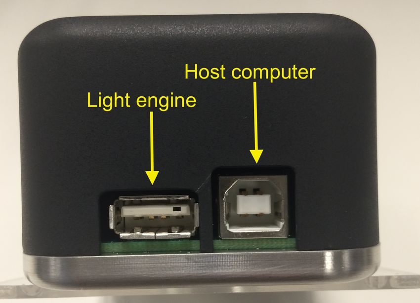
Regulatory Models
Lumencor utilizes regulatory model names for all certified and CE marked products. The regulatory model names are
traceable to all regulatory documentation, third party reports and certifications.

“Regulatory Model: Luma II” is used as a representative model for all certified and CE marked Luma II Products.
“Regulatory Model: Retra II” is used as a representative model for all certified and CE marked Retra II Products.

Emissions
This equipment has been tested and found to comply with the limits of EMC directive 2014/30/EU. These limits are
designed to provide reasonable protection against harmful interference when the equipment is operated in a commercial
environment. This equipment generates, uses, and can radiate radio frequency energy and, if not installed and used in
accordance with the instruction manual, may cause harmful interference to radio communications.

Safety Certifications
TÜV SÜD America, CB Certification (IEC 61010-1:2010)
TÜV SÜD America, NRTLus Certification (UL 61010-1:2012)
TÜV SÜD America, cNRTL Certification (CAN/CSA-C22.2 No. 61010-1:2012)
TÜV SÜD America, EN Certification (EN 61010-1:2010)

CE Marking
Low Voltage Directive (2014/35/EU)
EMC Directive (2014/30/EU)
RoHS Directive (2011/65/EU)
REACH Regulation (EC) No. (1907/2006/EC)

EU Declarations of Conformity can be found at http://lumencor.com/company/regulatory-compliance/

Lumencor, Inc.
14940 NW Greenbrier Parkway
Beaverton, OR 97006

T 503.213.4269

www.lumencor.com

Document Number 57-10013, Rev. A

!   LUMA Light Engine and RETRA Light Engine Instruction Manual                                                     2
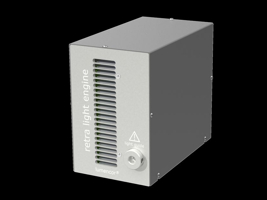
Table of Contents
1.   Introduction

2.   Precautions and Warnings

3.   Installation and Operating Instructions

4.   Product Specifications

5.   Routine Maintenance and Trouble Shooting

6.   Customer Support

7.   Warranty

!    LUMA Light Engine and RETRA Light Engine Instruction Manual   3
1. Introduction
Lumencor’s LUMA and RETRA light engines are designed for laboratory use by bioanalytical researchers and/or
developers of bio-optical instrumentation. The RETRA incorporates 2 individually controllable solid state light sources
that have been optimized to produce spectrally discrete spectral outputs. The LUMA contains a single solid state light
source. The outputs of the constituent light sources are refined by bandpass filters and merged into a common optical
train directed to the light output port on the front panel. The light output port has a built-in adapter for connection to an
SMA-terminated optical fiber or a liquid light guide (LLG).

The light sources within the LUMA and RETRA light engines are controlled by a serial command interface connecting to
the Lumencor light engine control pod accessory (83-10007) or a computer running a Lumencor supplied GUI or a third
party microscopy software application. Alternatively, the light sources may be enabled by TTL inputs from a trigger
device such as a camera or a real-time controller. The user can enable or disable each source independently (serial or
TTL) and change the intensity of each source independently (serial only).

!   LUMA Light Engine and RETRA Light Engine Instruction Manual                                                          4
2. Precautions and Warnings {Précautions et mises en garde}
A few simple practices will ensure trouble-free operation for the life of the light engine.

Les quelques règles simples suivantes permettront d’assurer un fonctionnement fiable pendant toute la durée de service
de la source lumineuse.

Safety Instructions:
Please read and follow all safety instructions provided BEFORE using your new LUMA or RETRA. Failure to comply with
the safety instructions may result in fire, electrical shock, or personal injury and may damage or impair protection
provided by equipment. Please save all safety instructions.

Instructions de sécurité:
Veiller à lire et à respecter toutes les instructions de sécurité fournies AVANT d’utiliser le nouveau LUMA ou RETRA afin
d’écarter les risques d’incendie, de décharge électrique, de blessure corporelle et de possibles dommages ou défaillance
de la protection offerte par l’appareil. Conserver toutes les instructions de sécurité.

Safety Definitions {Définitions relatives à la sécurité}:

                Warning: Statements identify conditions or practices that could result in personal injury.

               Avertissement: déclarations qui identifient des situations ou des pratiques susceptibles d’entraîner des
               blessures corporelles.
               Caution: Statements identify conditions or practices that could result in damage to your equipment.

Attention: déclarations qui identifient des situations ou des pratiques susceptibles d’endommager le matériel.

Safety Items {Mesures de sécurité}:

Warning: ONLY use the power supply provided by Lumencor. The Lumencor-supplied 24 VD C, 9.2 A external
power supply is required for use with the LUMA or RETRA light engine. The equipment is required to be supplied by a
properly approved/certified DC power source meeting the minimum electrical ratings of the product. The DC power
supply must have the AC power cord connected to a receptacle with a protective safety (earth) ground terminal.

Avertissement: utiliser uniquement l'alimentation fournie par Lumencor. Le Lumencor fourni 24 VDC/9.2 A
alimentation externe est recommandé pour une utilisation avec la source lumineuse LUMA ou RETRA. Il est impératif
que l'alimentation DC a la sortie protection contre les surintensités, que la puissance de la source lumineuse est pas
fusionné. L'alimentation DC doit répondre aux exigences d'un circuit courant limité par la clause 9.4 de la IEC 61010-1
3rd ed. Branchez le cordon d'alimentation à une prise avec une sécurité de protection (terre) borne de terre.

Warning: DO NOT stare into the output of the light engine. The brightness of this light source is higher than most
commercial lighting fixtures and is intended to couple directly into a microscope or other bioanalytjcal instrument.

Avertissement: NE PAS regarder directement la sortie de la source lumineuse. L’intensité lumineuse de cette source est
supérieure à celle de la majorité des appareils d’éclairage disponibles dans le commerce et est conçue pour un
raccordement direct à un microscope ou autre appareil de bioanalyse.

Warning: DO NOT turn on the light without the output end of the light guide safely directed into an enclosed
optical path. DO NOT point the light output directly onto any flammable or burn-susceptible material. This includes all
animal or vegetable tissues, plastics, fabrics, paper and liquids.

!   LUMA Light Engine and RETRA Light Engine Instruction Manual                                                      5
Avertissement: NE PAS allumer la lumière sans l'extrémité de sortie du guide de lumière dirigée en toute
sécurité dans un chemin optique fermé. NE PAS pointer la sortie de lumière directement sur un matériau susceptible
d'être inflammable ou susceptible de brûler. Cela comprend tous les tissus, les plastiques, les tissus, le papier et les liquides
animaux ou végétaux.
RISK GROUP 3
Warning: Possibly hazardous optical radiation emitted from this product. Do not look at operating lamp. Eye injury may
result.
Warning: UV emitted from this product. Avoid eye and skin exposure to unshielded product.
Warning: IR emitted from this product. Do not look at operating lamp.
GROUPE DE RISQUE 3
Avertissement: Rayonnement optique Peut-être dangereux émis par ce produit . Ne regardez pas la lampe
d'exploitation. Une blessure oculaire peut entraîner.
Avertissement: UV émis par ce produit . Évitez les yeux et la peau exposition au produit non blindé.
Avertissement: IR émise par ce produit. Ne regardez pas la lampe d’exploitation.
AC Power Cords
Caution: DO NOT open the unit. There are no serviceable parts inside and Region Part Number
opening the light engine enclosure will void the manufacturer’s warranty. North America 29-10002
Europe 29-10005
Attention: NE PAS ouvrir l’appareil. Il ne contient aucune pièce réparable et
United Kingdom 29-10004
l’ouverture de son boîtier a pour effet d’annuler la garantie.
Israel 29-10008
Caution: DO NOT connect a video cable to the TTL input enable port. Australia/New Zealand 29-10024
Although the connector might look compatible, this input is not intended to be driven by a video signal.
Attention: NE PAS raccorder un câble vidéo au port d’activation d’entrée TTL. Bien que le connecteur puisse
paraître compatible, cette entrée n’est pas conçue pour être contrôlée par un signal vidéo.
Caution: DO NOT set liquids on the light engine. Spilled liquids may damage your light engine.
Attention: NE PAS placer de liquide sur la source lumineuse. Les liquides renversés peuvent endommager la
source lumineuse.
Caution: DO NOT drop the light engine. It contains glass optical components that could be damaged or misaligned
by the shock produced by a drop onto a hard surface.
Attention: NE PAS laisser tomber la source lumineuse. Elle contient des composants optiques en verre susceptibles
d’être endommagés ou désalignés par le choc résultant d’une chute sur une surface dure.
! LUMA Light Engine and RETRA Light Engine Instruction Manual 6DISCLAIMER: Lumencor shall not be liable for injury to the user or damage to the product resulting from the
LUMA or RETRA being used in a way for which it was not intended and in complete disregard for all posted
safety precautions and warnings.
AVIS DE NON-RESPONSABILITÉ: Lumencor décline toute responsabilité pour les blessures corporelles ou
les dommages au produit résultant d’une utilisation du LUMA ou RETRA autre que celle prévue et du mépris
total de toutes les mesures de sécurité et mises en garde affichées.
3. Installation and Operating Instructions
3.1 Installation
All LUMA and RETRA light engines ship with the following list of standard AC Power Cords
components: Region Part Number
North America 29-10002
1. A light engine, configured with one (LUMA) or two (RETRA) solid-state light
Europe 29-10005
sources (color channels). The output of each source is refined by a bandpass
United Kingdom 29-10004
filter. The filter configuration for each light engine is shown on the certificate of
Israel 29-10008
conformance issued to the customer when the light engine is shipped by
Lumencor (Figure 1). Australia/New Zealand 29-10024
2. A 24V/9.2A (220 W) DC power supply (Lumencor part no. 27-10019)
3. A region-specific AC power cord for the power supply
(see adjacent table)
4. A USB B (M) to USB A (M) cable (Lumencor part no.
29-10058)
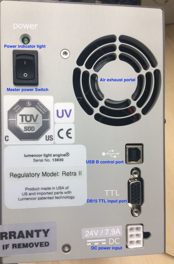
LUMA and RETRA engines incorporate fan-assisted air
cooling. When positioning the light engine for use, place the
unit on a hard surface and avoid blocking or restricting airflow
at the air intake (front panel) and exhaust (rear panel; Figure 2)
ports. Restricting the airflow will cause the unit to operate at
elevated temperatures and will result in decreased operating
lifespan and/or premature failure.
Connect the DC power supply to a grounded AC wall outlet
using the power cord supplied with the light engine. Connect
the DC output to the 6-pin receptacle on the rear of the light
engine (Figure 2). Turn the light engine on using the master
power switch on the rear panel. The green indicator LED
above the power switch will illuminate ((if applicable, ensure
that the liquid light guide is inserted and secured; see below).
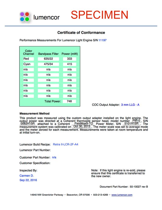
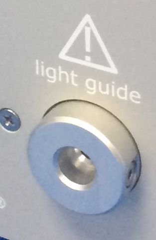
LUMA and RETRA engines may be configured for light Figure 1. Specimen certificate of conformance (C of C)
delivery via a 3 mm liquid light guide or an SMA-terminated for RETRA Light Engine.The C of C identifies the color
optical fiber. The output couplers are built into the light engine channels installed in the light engine and the bandpass
front panel and are not field-exchangeable (Figure 3). The 3 filters associated with each channel. Full (100%) power
mm liquid light guide output coupler incorporates an electrical outputs measured at the terminus of the liquid light guide
power interlock switch in the back of the receptacle. The liquid (LLG) or optical fiber are recorded in the third column.
light guide must be fully inserted in the receptacle to activate
! LUMA Light Engine and RETRA Light Engine Instruction Manual 7the interlock. Electrical power supply to the light
engine cannot be turned on via rear panel power
switch until the interlock is activated. After fully
inserting the liquid light guide,
lock it in position using the set screw on the right-
hand side of the receptacle (Figure 3) to prevent
inadvertent disconnection of the light guide during
use.
Light source outputs are refined by bandpass filters.
The specifications of these bandpass filters are
recorded on the certificate of conformance as CWL/
FWHM where CWL =center wavelength and FWHM
= full width at half-maximum transmission, both
measure in nanometers (nm). Bandpass filters are
not user-exchangeable and changes require return
of the light engine to Lumencor’s factory for service
(see Section 6). Since changing bandpass filters will
result in source output power changes, a new
certificate of conformance will be provided as part of
this service.
The LUMA and RETRA can be controlled via serial
commands delivered through the USB port from the
Lumencor light engine control pod accessory
(83-10007), a Windows GUI (free download from
www.lumencor.com) or via customer-supplied data
acquisition software. Serial commands provide
controls for on/off switching and intensity
adjustment (0 to 100% in 1% increments) of
Figure 2. RETRA Light Engine rear panel.
individual color channels. TTL signals delivered to
the DB15 connector (Figure 2) provide high speed (10 µs) on/off switching of individual color
channels.
3.2 GUI Control Interface
1. Operation and installation of the LUMA and RETRA GUI requires a computer
running the Windows operating system with a free USB port.
2. Download the zip file for the LUMA and RETRA GUI from http://lumencor.com/
resources/documentation-software/.
3. Unzip the file and run setup.exe to install the LUMA and RETRA GUI.
4. Connect the USB-B (M) to-USB A-(M) cable between the computer and the USB
B (F) port on the light engine (Figure 2).
5. Successful installation is indicated by the appearance of “USB Serial Port (COM
#)” under the “Ports (COM &LPT)” tab in the Windows Device Manager. If the
virtual COM port (VCP) is not registered by the operating system, download and Figure 3. Front panel light
install the VCP driver from http://lumencor.com/resources/documentation- output port with receptacle
software/. for 3 mm diameter liquid
light guide.
! LUMA Light Engine and RETRA Light Engine Instruction Manual 86. If applicable, check that the liquid light guide is fully inserted and locked in the front panel receptacle (Figure 3).
7. Toggle the master power switch on the rear panel to the ON position. The green LED above the switch (Figure
2) should light.
8. Run the GUI by going to the Program Menu and selecting LLE Controller.
9. In the COM pulldown menu (GUI window, upper left), select COM # assigned to USB-Serial port.
10. Press the “INIT” button in the GUI.
11. The computer should now have control of the light engine. Graduated sliders control the source output
intensity for each color channel. ON/OFF buttons for each color channel are located below the respective slider
controls [1].
Notes
[1] The identity of the source outputs corresponding to control channels 1–3 differs among LUMA and RETRA light
engine models. If you are unsure of the correspondence, please contact our Technical Support Group (see Section
6). Please provide notification of the serial number of your light engine with your inquiry.
3.3 Light Engine Control Pod Interface
1. Connect the USB A port of the light engine control pod
accessory (Figure 4) to the USB B port on the light engine
(Figure 2) using the USB-A to-USB B cable (29-10058). If
pass-through communication from a host computer is
required, connect the USB B port of the control pod to a
USB A port on the computer.
2. Press and hold the right button on the pod until a menu
of light engines appears. Turn the rotary dial to select
“RETRA” from the menu. Press the right button again to
return to the main (0–100 analog intensity) display screen.
3. Press the left button to select the desired color channel.
Successive presses will cycle through the available color
channels.
4. Press the right button to turn the selected light source Figure 4. USB connectors on rear of the light
on. Adjust the output intensity using the rotary dial [1]. engine controller pod
Press the right button again to turn the selected light
source off.
5. Press and hold the left button to obtain digital output intensity settings for each color channel [2]. Press the
right button to return to the main display screen.
Notes
[1] Turning the intensity to zero will turn the source off. Press the right button to turn the source on again before
continuing to adjust the intensity.
[2] The current intensity settings are internally stored. When the pod is powered down, the settings are retained
and will be restored at the next restart.
3.3 TTL Interface
The TTL Interface provides users with a faster method of switching color TTL Connector Pin Definitions
channel outputs on and off. Individual TTL lines are provided for each color Channel Pin#
channel. These can be conveniently addressed using an accessory BNC 1 1
breakout cable (Lumencor part no. 29-10081) connected to the rear panel 2 3
3 2
DB15 port (Figure 2). As a safeguard against unintended light output when
Ground 6,7,8,10
the inputs are initially connected, the TTL port is disabled and must be Maximum input voltage = 5.5 V
! LUMA Light Engine and RETRA Light Engine Instruction Manual 9enabled by a serial command. To enable the TTL port, establish a serial connection as described in Section 3.2 and click
the TTL ON (SFT) button in the GUI. A description of the serial command string for this operation is available on request
from Lumencor Technical Support (Section 6). Note that TTL and serial on/off commands have a logical OR relationship.
Therefore on/off controls in the GUI or other serial control software must be set in the “OFF” state when using TTL
control. TTL polarity (ACTIVE = HIGH or ACTIVE = LOW) is factory set according to order specifications. TTL polarity
can be reversed using controls provided in the GUI.
4. Product Specifications
LUMA and RETRA light engines must be operated and stored within the environmental conditions specified.
Specification Detail
Temperature
Operating 32 to 95° F (0 to 35° C)
Non-operating -4 to 158° F (-20 to 70° C)
Humidity
Operating and non-operating 0 to 80% relative humidity, non-condensing
Altitude
Operating 0 to 10,000 feet (3,048 meters)
Non-operating 0 to 45,000 feet (13,176 meters)
Dimensions
Size (W x L x H) 105 mm x 187 mm x 159 mm (4.1 in x 7.4 in x 6.3 in)
Weight (RETRA) 2.8 kg (6.2 lb)
Weight (LUMA) 2.3 kg (5.0 lb)
Time for light engine output to decrease to 70% of the values recorded on the
Lifetime
original certificate of conformance¶
Input Power Requirements 24 V DC / 7.9 A
Warm-up Period 1s
Ingress Protection IP Rating of X0
Sound Level Sound level at 1 meter < 65dB(A)
Control Interfaces Serial (USB to RS-232), TTL
Warranty 36 months parts and labor‡
¶The corresponding number of days/months/years may vary considerably depending on the duty cycle implemented
by the user and the environmental conditions prevailing during operation. ‡18 months for RETRA FURA light engine
(90-10361)
Performance specifications for individual light engines are listed on the certificate of conformance included with the
shipping documents e-mailed to the customer (see example shown in Figure 1). It is important to retain the certificate of
conformance for reference. In the event that the light engine is sold, the certificate of conformance should be transferred
to the new owner. Certificates of conformance are also recorded in Lumencor’s database and copies can be requested
! LUMA Light Engine and RETRA Light Engine Instruction Manual 10by e-mail to techsupport@lumencor.com. The request message must include the 4- or 5-digit serial number of the light engine. 5. Routine Maintenance and Trouble Shooting No routine maintenance is required. There are no user-replaceable components or sub-assemblies in the LUMA and RETRA light engines. Opening the light engine enclosure will void the manufacturer’s warranty. In the event that the light engine fails to perform in accordance with the specifications listed on the certificate of conformance, please contact Lumencor Technical Support for assistance, as directed in Section 6. 6. Customer Support For technical support of LUMA and RETRA light engines, please contact Lumencor by phone at 503.213.4269 or via e- mail at techsupport@lumencor.com. Please be prepared to provide the 4- or 5-digit serial number of the light engine, a description of the problems encountered and information on the usage context (e.g. what microscope and what control software is being used). This information will help to determine whether the problems can be resolved in situ by adjustments to the system configuration, or whether a fault has developed in the light engine that requires its return to Lumencor’s facility in Beaverton, Oregon for evaluation and, if necessary, repair. Any light engine return to Lumencor for service or repair requires a material authorization (RMA) number. To obtain a RMA number, submit the online request form at http://lumencor.com/support/lumencor-rma-request-form. It is the customer’s responsibility to properly package and safely ship products to Lumencor. Instructions for shipping will be provided in the e-mail giving notification of the RMA number. 7. Warranty LUMA and RETRA light engines are backed by a 36 month warranty. Warranty coverage starts on the original date of shipment from Lumencor. Light Engines qualifying for warranty service must be verifiably delivering performance that is substantially at variance with the levels documented in the certificate of conformance. The light engine must also have been used and maintained under operating conditions consistent with the specifications given in Section 4, and observing all the Precautions and Warnings notified in Section 2. This warranty does not extend to light engines that have been subject to misuse, accident, tampering or improper installation. Accessories including (but not limited to) liquid light guides, optical fibers, collimators, cables and control consoles are not covered by the warranties attached to light engines. Please fill out and submit the online warranty registration form. This will facilitate provision of warranty service should it be required. ! LUMA Light Engine and RETRA Light Engine Instruction Manual 11
Vous pouvez aussi lire