Direct Vent Tankless Water Heater Installa on and Opera on Manual
←
→
Transcription du contenu de la page
Si votre navigateur ne rend pas la page correctement, lisez s'il vous plaît le contenu de la page ci-dessous
Direct Vent Tankless Water Heater
                                                  Installa on and Opera on Manual
FOR INDOOR APPLICATIONS ONLY

RL75i .....................REU‐VC2528FFUD‐US
                           REU‐VC2528FFUD(A)‐US
RL94i .....................REU‐VC2837FFUD‐US
FOR OUTDOOR APPLICATIONS ONLY
RL75e ....................REU‐VC2528WD‐US
                          REU‐VC2528WD(A)‐US
RL94e ....................REU‐VC2837WD‐US

                                              ANS Z21.10.3 ● CSA 4.3

READ ALL OF THE INSTRUCTIONS THOROUGHLY BEFORE INSTALLING OR OPERATING THIS WATER HEATER.
This manual provides informa on on the installa on, opera on, and maintenance of the water heater. For proper
opera on and safety, it is important to follow the instruc ons and adhere to the safety precau ons.
A licensed professional must install the water heater according to the exact instruc ons on pages 4‐30.
The consumer must read the en re manual to properly operate the water heater and to have regular maintenance
performed.

       WARNING          If the informa on in these instruc ons is not followed exactly, a fire or explosion
                        may result causing property damage, personal injury or death.
— Do not store or use gasoline or other flammable vapors and liquids in the vicinity of this or any other
  appliance.
— WHAT TO DO IF YOU SMELL GAS
   •    Do not try to light any appliance.
   •    Do not touch any electrical switch; do not use any phone in your building.
   •    Immediately call your gas supplier from a neighbor’s phone. Follow the gas supplier’s instruc ons.
   •    If you cannot reach your gas supplier, call the fire department.
— Installa on and service must be performed by a licensed professional.

        This en re manual must be le for the consumer. The consumer must read and
          refer to this manual for proper opera on and to maintain the water heater.
Table of Contents
Table of Contents ..................................................... 2 Final Checklist .................................................. 24
Safety Behaviors and Prac ces for the Technical Data ........................................................ 25
Consumer and Installer ............................................ 3 Specifica ons ................................................... 25
Installa on Instruc ons Dimensions ...................................................... 26
(for the licensed professional) .............................. 4 Pressure Drop and Water Flow Curves ............ 27
Prepare for Installa on ...................................... 5 Ladder Diagram................................................ 28
Determine Installa on Loca on ........................ 6 Recircula on Mode .......................................... 29
Checklist to Determine Installa on Loca on... 12 Opera on Instruc ons........................................ 31
Mount to Wall .................................................. 12 Consumer Opera on Guidelines for the
Remove the Front Panel .................................. 12 Safe Opera on of your Water Heater.............. 32
Installa on of Ven ng (indoor models only) ... 13 How to Use the Temperature Controller ......... 33
Condensate (indoor models only) ................... 15 How to Set the Temperature ........................... 34
Checklist for Ven ng and Condensate Diagnos c Codes .............................................. 36
(indoor models only)........................................ 15 Required Maintenance .................................... 39
Installa on of Plumbing ................................... 16
Flushing the Heat Exchanger ..................... 41
Checklist for Plumbing ..................................... 19
Manual Draining of the Water Heater ...... 42
Installa on of Gas Supply ................................ 19
State Regula ons.................................................... 43
Connect Electricity ........................................... 21
Replacement Parts ................................................. 44
Adjust for High Al tude ................................... 21
Consumer Warranty ............................................... 45
Adjust for Vent Length (indoor models only) .. 21
Checklist for Gas and Electricity ...................... 21 French Version........................................................ 48
Installa on of Temperature Controller ........... 22
NOTICE: Rinnai some mes shares customer contact informa on with businesses that we believe provide
products or services that may be useful to you. By providing this informa on, you agree that we can
share your contact informa on for this purpose. If you prefer not to have your informa on shared with
these businesses, please contact customer service and ask not to have your informa on shared. We
will however, con nue to contact you with informa on relevant to the product(s) you registered and/
or you account with us.
If you have any ques ons or feel that the manual is incomplete contact Rinnai at 1‐800‐621‐9419.
Important Safety Informa on
Safety Defini ons
This is the safety alert symbol. This symbol alerts you to poten al hazards that can kill or hurt you
and others.
DANGER Indicates an imminently hazardous situa on which, if not avoided, will result in death or
serious injury.
WARNING Indicates a poten ally hazardous situa on which, if not avoided, could result in death or
serious injury.
CAUTION Indicates a poten ally hazardous situa on which, if not avoided, could result in minor or
moderate injury. It may also be used to alert against unsafe prac ces.
2 VC Series ManualSafety Behaviors and Prac ces for the Consumer and Installer
WARNING
• Before opera ng, smell all around the appliance • Use only your hand to push in or turn the gas
area for gas. Be sure to smell next to the floor control knob. Never use tools. If the knob will not
because some gas is heavier than air and will se le push in or turn by hand, do not try to repair it; call a
on the floor. licensed professional. Force or a empted repair
may result in a fire or explosion.
• Keep the area around the appliance clear and free
from combus ble materials, gasoline, and other • Do not use this appliance if any part has been under
flammable vapors and liquids. water. Immediately call a licensed professional to
inspect the appliance and to replace any part of the
• Combus ble construc on refers to adjacent walls control system and any gas control which has been
and ceiling and should not be confused with
under water.
combus ble or flammable products and materials.
Combus ble and/or flammable products and • Do not use subs tute materials. Use only parts
materials should never be stored in the vicinity of cer fied with the appliance.
this or any gas appliance.
• Should overhea ng occur or the gas supply fail to
• Always check the water temperature before shut off, turn off the manual gas control valve to the
entering a shower or bath. appliance.
• To protect yourself from harm, before performing • Do not adjust the DIP switch unless specifically
maintenance: instructed to do so.
◊ Turn off the electrical power supply by
unplugging the power cord or by turning off the
• Do not use an extension cord or an adapter plug
with this appliance.
electricity at the circuit breaker. (The
temperature controller does not control the • Any altera on to the appliance or its controls can be
electrical power.) dangerous and will void the warranty.
◊ Turn off the gas at the manual gas valve, usually
located immediately below the water heater.
◊ Turn off the incoming water supply. This can be
done at the isola on valve immediately below
the water heater or by turning off the water
supply to the building.
CAUTION
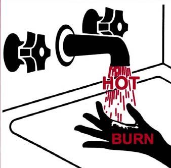
• BURN HAZARD. Hot exhaust and vent may cause • Hot water outlet pipes leaving the unit can be hot
serious burns. Keep away from water heater unit. to touch. In residen al applica ons, insula on
Keep small children and animals away from unit. must be used for hot water pipes below 36” due to
burn risk to children.
California law requires this no ce to be provided:
California Proposi on 65 lists chemical substances known to the state to cause cancer, birth defects, death,
serious illness or other reproduc ve harm. This product may contain such substances, be their origin from fuel
combus on (gas, oil) or components of the product itself.
VC Series Manual 3Installa on Instruc ons
Installer Qualifica ons General Instruc ons
A licensed professional must install the appliance, DO NOT
inspect it, and leak test it before use. The warranty
• Do not install the RL75i or the RL94i outdoors.
will be voided due to improper installa on.
• Do not install the RL75e or the RL94e indoors.
The installer should have skills such as:
• gas sizing • Do not install the appliance in an area where water
leakage of the unit or connec ons will result in
• connec ng gas lines, water lines, valves,
damage to the area adjacent to the appliance or to
electricity,
lower floors of the structure. When such loca ons
• knowledge of applicable na onal, state, and cannot be avoided, it is recommended that a
local codes. suitable drain pan, adequately drained, be installed
• installing ven ng through a wall or roof under the appliance. The pan must not restrict
If you lack these skills contact a licensed professional. combus on air flow.
• Do not obstruct the flow of combus on and
ven la on air. Combus on air shall not be
supplied from occupied spaces.
Type of installa on • Do not use this appliance in an applica on such as
• For installa on in residen al and commercial a pool or spa heater that uses chemically treated
applica ons. water . (This appliance is suitable for filling large or
whirlpool spa tubs with potable water.)
• Cer fied for installa on in manufactured (mobile)
homes. • Do not use subs tute parts that are not authorized
for this appliance.
Installa on Steps MUST DO
Prepare for Installa on ...................................... 5 • The installa on must conform with local codes or,
Determine Installa on Loca on ........................ 6 in the absence of local codes, with the Na onal
Fuel Gas Code, ANSI Z223.1/NFPA 54, or the
Checklist to Determine Installa on Loca on ... 12 Natural Gas and Propane Installa on Code, CSA
Mount to Wall .................................................. 12 B149.1. If installed in a manufactured home, the
Remove the Front Panel .................................. 12 installa on must conform with the Manufactured
Installa on of Ven ng (indoor models only) ... 13 Home Construc on and Safety Standard, Title 24
CFR, Part 3280 and/or CAN/SCA Z240 MH Series,
Condensate (indoor models only).................... 15
Mobile Homes.
Checklist for Ven ng and Condensate
• The appliance, when installed, must be electrically
(indoor models only) ........................................ 15
grounded in accordance with local codes or, in the
Installa on of Plumbing ................................... 16 absence of local codes, with the Na onal Electrical
Checklist for Plumbing ..................................... 19 Code, ANSI/NFPA 70, or the Canadian Electrical
Installa on of Gas Supply ................................ 19 Code, CSA C22.1.
Connect Electricity ........................................... 21 • The appliance and its appliance main gas valve
Adjust for High Al tude ................................... 21 must be disconnected from the gas supply piping
Adjust for Vent Length (indoor models only) .. 21 system during any pressure tes ng of that system
at test pressures in excess of 1/2 psi (3.5 kPa)
Checklist for Gas and Electricity ....................... 21 (13.84 in W.C.).
Installa on of Temperature Controller ............ 22
Final Checklist .................................................. 24
4 VC Series ManualPrepare for installa on
• The appliance must be isolated from the gas supply
piping system by closing its individual manual Parts included
shutoff valve during any pressure tes ng of the gas
• Tankless water heater
supply piping system at test pressures equal to or
less than 1/2 psi (3.5 kPa) (13.84 in W.C.). • Color coded cold (blue) and hot (red) isola on
valves
• You must follow the installa on instruc ons and
those in Care and Maintenance for adequate • Pressure relief valve
combus on air intake and exhaust.
• MC‐91‐2 temperature controller (integrated into
INFORMATION indoor models; provided with outdoor models)
• If a water heater is installed in a closed water
supply system, such as one having a backflow Tools needed
preventer in the cold water supply line, means • Pipe wrenches (2) • Gloves
shall be provided to control thermal expansion.
Contact the water supplier or local plumbing • Adjustable pliers • Safety glasses
inspector on how to control thermal expansion. • Screwdrivers (2) • Level
• Should overhea ng occur or the gas supply fail to • Wire cu ers
shut off, turn off the manual gas control valve to
the appliance. Tools that might be needed
• Keep the air intake loca on free of chemicals such
• Hammer drill with • Core drill with diamond
as chlorine or bleach that produce fumes. These
concrete bits head
fumes can damage components and reduce the life
of your appliance. • Saw • Torch set
• Threading machine with • Copper tubing cu er
heads and oiler
• Steel pipe cu er
Materials needed
• Soap solu on • Teflon tape
(recommended) or pipe
• Approved ven ng compound
Materials that may be needed
• Heat tape • 5/8” ID PVC flexible
tubing
• Pipe insula on
• 2 conductor 22 AWG
• Electrical wire and
wire for controller
conduit per local code
• Single gang electrical
• Concrete wall anchors box
• Op onal pipe cover
• Wire nuts
• Op onal temperature
• Unions and drain valves
controller
VC Series Manual 5Determine Installa on Loca on
You must ensure that clearances will be met and that Environment
the vent length will be within required limits.
Air surrounding the water heater, ven ng, and vent
Consider the installa on environment, water quality,
termina on(s) is used for combus on and must be
and need for freeze protec on. Requirements for the
free of any compounds that cause corrosion of
gas line, water lines, electrical connec on, and
internal components. These include corrosive
condensate disposal can be found in their respec ve
compounds that are found in aerosol sprays,
installa on sec ons of this manual.
detergents, bleaches, cleaning solvents, oil based
Water Quality paints/ varnishes, and refrigerants. The air in beauty
shops, dry cleaning stores, photo processing labs, and
Considera on of care for your water heater should storage areas for pool supplies o en contains these
include evalua on of water quality. compounds. Therefore it is recommended that
Water that contains chemicals exceeding the levels outdoor models be used for these loca ons where
below affect and damage the heat exchanger. possible.
Replacement of the heat exchanger due to water The water heater, ven ng, and vent termina on(s)
quality damage is not covered by the warranty. should not be installed in any areas where the air may
Maximum Level contain these corrosive compounds. If it is necessary
Total Hardness Up to 200 mg / L for a water heater to be located in areas which may
Aluminum * Up to 0.2 mg / L contain corrosive compounds, the following
Chlorides * Up to 250 mg / L
instruc ons are strongly recommended.
Copper * Up to 1.0 mg / L IMPORTANT CONSIDERATIONS FOR:
Iron * Up to 0.3 mg / L Indoor/Internal Water Heaters
Manganese * Up to 0.05 mg / L
• DO NOT Install in areas where air for combus on
pH * 6.5 to 8.5 can be contaminated with chemicals.
TDS (Total Dissolved Solids) * Up to 500 mg / L
• Before installa on, consider where air has the
Zinc * Up to 5 mg / L
ability to travel within the building to the water
* Source: Part 143 Na onal Secondary Drinking Water heater.
Regula ons
• Where possible, install the water heater in a
If you install this water heater in an area that is sealed closet so that it is protected from the
known to have hard water or that causes scale build‐ poten al of contaminated indoor air.
up the water must be treated and/or the heat • Chemicals that are corrosive in nature should not
exchanger flushed regularly. be stored or used near the water heater.
When scale build‐up in the heat exchanger begins to Outdoor/External Water Heaters and Vent
affect the performance of the water heater, a Termina ons of Indoor/Internal Water Heaters
diagnos c code “LC#” will display. Flush the heat • Install the water heater as far away as possible
exchanger to prevent damage to it. Scale build up is from exhaust vent hoods.
caused by hard water set at a high temperature.
• Install as far away as possible from air inlet
Rinnai provides a “Scale Control System” that offers vents. Corrosive fumes may be released through
superior lime scale preven on and corrosion control these vents when air is not being brought in
by feeding a blend of control compounds into the through them.
cold water supply.
• Chemicals that are corrosive in nature should not
103000022 103000023 103000024 be stored or used near the water heater or vent
Installed on cold Whole home or Light Whole home supply‐ termina on.
water line supplying Commercial supply‐ ing 2 tankless water Damage and repair due to corrosive compounds in
1 tankless water ing 1 tankless water heaters or 1 tankless
heater only heater in Light Commercial
the air is not covered by warranty.
Refill 103000025 Refill 103000026 Refill 103000026
6 VC Series ManualVent Termina on Clearances
For indoor models, you must install a vent termina on to bring in combus on air and expel exhaust.
TERMINATION INSIDE
CORNERDETAIL
G
Clearance in
Ref. A also H
applies to
A
anticipated
snow line
SNOW
I M
B
D FIXED
B K
CLOSED
E OPERABLE
B
C J
B
FIXED
CLOSED
B
A
X AIR SUPPLY INLET
OPERABLE
L V VENT TERMINAL
F AREA WHERE TERMINAL
IS NOT PERMITTTED
B
Ref Descrip on Canadian Installa ons US Installa ons
A Clearance above grade, veranda, porch, deck, or balcony 12 inches (30 cm) 12 inches (30 cm)
B Clearance to window or door that may be opened 36 inches (91 cm) 12 inches (30 cm)
C Clearance to permanently closed window * *
Ver cal clearance to ven lated soffit, located above the terminal within
D a horizontal distance of 2 feet (61 cm) from the center line of the * *
terminal
E Clearance to unven lated soffit * *
F Clearance to outside corner * *
G Clearance to inside corner * *
Clearance to each side of center line extended above meter/regulator 3 feet (91 cm) within a height 15
H *
assembly feet (4.5 m) above the meter/
I Clearance to service regulator vent outlet 36 inches (91 cm) *
Clearance to nonmechanical air supply inlet to building or the
J 36 inches (91 cm) 12 inches (30 cm)
combus on air inlet to any other appliance
3 feet (91 cm) above if within 10
K Clearance to a mechanical air supply inlet 6 feet (1.83 m)
feet (3 m) horizontally
Clearance above paved sidewalk or paved driveway located on public
L 7 feet (2.13 m) 1 *
property
M Clearance under veranda, porch, deck, or balcony 12 inches (30 cm) 2 *
[1] A vent shall not terminate directly above a sidewalk or paved driveway ∗ For clearances not specified in ANSI Z223.1/NFPA 54, clearances are in
that is located between two single family dwellings and serves both accordance with local installa on codes and the requirements of the gas
dwellings. supplier.
[2] Permi ed only if veranda, porch, deck, or balcony is fully open on a Clearance to opposite wall is 24 inches (60 cm).
minimum of two sides beneath the floor.
VC Series Manual 7Addi onal clearances ‐ RL75i, RL94i 60"
(1.52 m)
V
Check on whether local codes supersede these clearances. between
• Avoid termina on loca ons near a dryer vent. terminals at
different levels V
• Avoid termina on loca ons near commercial
cooking exhaust.
• You must install a vent termina on at least 12
inches from the ground.
Important considera ons for loca ng vent
termina on under a soffit (ven lated or unven lated
or eave vent; or to a deck or porch) V
• Do not install vent termina on under a soffit vent
such that exhaust can enter the soffit vent (1.52 m) ver cally
60" between terminals
• Install vent termina on such that exhaust and
rising moisture will not collect under
eaves. Discolora on to the exterior of the
building could occur if installed too close. V
• Do not install the vent termina on too close
under the soffit where it could present
recircula on of exhaust gases back into the
combus on air intake part of the termina on.
(0.61 m) to wall or parapet
24"
V
36"
12"
(0.30 m ) to V V
an inside 12"
corner
(0.30 m) between
terminals at same
level 12" (0.30 m) between
V V terminals at same
level
INSIDE
CORNER
8 VC Series ManualAddi onal clearances
RL75e, RL94e
Local codes supersede these clearances.
• Avoid termina on loca ons near a dryer vent.
• Avoid termina on loca ons near commercial
cooking exhaust.
(0.91 m) to ven lated or unven lated
36" soffit or eve vent; or to a deck or porch
12" 2"
(0.30 m) to an (50 mm) between terminals at same level
inside corner
60" (1.52 m) ver cally
between terminals
VC Series Manual 9Unit clearances
to top to top
to side
to side
to front
to front
to ground/bottom
to ground/bottom
Indoor models: RL75i, RL94i Outdoor models: RL75e, RL94e
to Non‐ to Non‐
to Combus bles to Combus bles
Combus bles Combus bles
inches (mm) inches (mm)
inches (mm) inches (mm)
Top of Heater 6 * (152) 2 *(51) Top of Heater 12 (305) 2 (51)
Back of Heater 0 (zero) 0 (zero) Back of Heater 0 (zero) 0 (zero)
Front of Heater 6 (152) 6 (152) Front (Panel) 24 (610) 0 (zero)
Sides of Heater 2 (51) 1/2 (13) Front (Exhaust) 24 (610) 24 (610)
Ground/Bo om 12 (305) 12 (305) Sides of Heater 6 (152) 1/8 (3.2)
Vent 0 (zero) 0 (zero) Ground/Bo om 12 (305) 2 (51)
* 0 inches from vent components and condensate The clearance for servicing is 24 inches in front of the
drain line. water heater.
The clearance for servicing is 24 inches in front of the
water heater.
For closet installa on, clearance is 6 inches (152 mm)
from the front.
10 VC Series ManualMaximum vent length Freeze Protec on
(indoor models only) Make sure that in case of freezing weather that the
water heater and its water lines are protected to
1. Determine the number of 90 degree elbows in prevent freezing. Damage due to freezing is not
the vent system. (Two 45 degree elbows count as covered by the warranty.
one 90 degree elbow.)
Loss of freeze protec on may result in water damage
2. Refer to the table to find the maximum vent from a burst heat exchanger or water lines.
length based on the number of elbows.
With electrical power supplied, the water heater will
Number of Maximum vent length not freeze when the outside air temperature is as cold
90° Elbows as –22°F (‐30°C) for indoor models or is as cold as –4°F
(‐20°C) for outdoor models, when protected from
0 41 (12.5 m) 1 direct wind exposure. Because of the “wind‐chill”
1 35 (10.7 m) 2 effect, any wind or circula on of the air on the unit
will reduce its ability to freeze protect.
2 29 (8.8 m) 3
The unit may be drained manually. However, it is
3 23 (7.0 m) 4 highly recommended that:
4 17 (5.2 m) 4 • drain down solenoid valves are installed that will
5 11 (3.4 m) 4 automa cally drain the unit if power is lost.
These are available in a kit, 104000059. (The
6 5 (1.5 m) 4 condensate trap drain plug and water drain plug
3. Adjust switch No. 1 in the SW1 DIP switch (tan are not affected by the auto drain down solenoid
switches) if required by the applicable note. valves and will have to be manually opened.)
1 If the length is greater than 21 (6.4 m) then • a surge protector with terminals is installed which
move switch No. 1 (SW1) to OFF. allows the solenoid valves to operate if the unit is
disabled due to a diagnos c code. This is
2 If the length is greater than 15 (4.6 m) then
available as 104000057.
move switch No. 1 (SW1) to OFF.
In addi on, the solenoid valves should be connected
3 If the length is greater than 9 (2.7 m) then move
electrically to a surge protector with terminals. This
switch No. 1 (SW1) to OFF.
allows the solenoid valves to operate if the water
4 Move switch No. 1 (SW1) to OFF. heater is disabled due to a diagnos c code.
Example: If you have one elbow then your maximum The freeze protec on features will not prevent the
vent length is 35 feet (10.7 m). If your external piping from freezing. It is recommended that
actual length is greater than 15 (4.6 m) hot and cold water pipes are insulated. Pipe cover
then move switch no. 1 (SW1) to OFF. enclosures may be packed with insula on for added
freeze protec on.
In the event of a power failure at temperatures below
freezing the water heater should be drained of all
water to prevent freezing damage. In addi on, drain
NOTICE the condensate trap and drain line.
If you have a longer vent length (see above), switch
No. 1 is required to be in the OFF posi on. This
ensures the water heater will run properly. Blocked
flue diagnos c codes and shutdowns may result if
switch No. 1 is not in the correct posi on.
VC Series Manual 11Checklist to Determine Installa on Mount to Wall
Loca on
□ The water heater is not exposed to corrosive
compounds in the air.
□ The water heater loca on complies with the
clearances. wall installa on
brackets
□ For indoor models, the planned ven ng will not
exceed the maximum length for the number of
elbows used.
□ The planned ven ng termina on/air intake
loca on meets the clearances.
□ The water supply does not contain chemicals or
exceed total hardness that will damage the heat 1. Iden fy the installa on loca on and confirm that
exchanger. the installa on will meet all required clearances.
□ A standard 3 prong 120 VAC, 60 Hz properly 2. Securely a ach the water heater to the wall
using any of the holes in the wall installa on
grounded wall outlet (for indoor models) or other
brackets which are at the top and bo om of the
120 VAC, 60 Hz source is available.
water heater. Ensure that the a achment
□ The installa on must conform with local codes or, strength is sufficient to support the weight.
in the absence of local codes, with the Na onal Refer to the weight of the water heater in the
Fuel Gas Code, ANSI Z223.1/NFPA 54, or the Specifica ons sec on.
Natural Gas and Propane Installa on Code, CSA Use a leveling tool to ensure that the water
B149.1. If installed in a manufactured home, the heater is level. Proper opera on requires that
installa on must conform with the Manufactured the water heater be level.
Home Construc on and Safety Standard, Title 24 NOTE: The water heater should be installed in an
CFR, Part 3280 and/or CAN/SCA Z240 MH Series, upright posi on. Do not install upside down or on its
Mobile Homes. side.
□ Leave the en re manual taped to the water
heater (indoor models), temperature controller Remove the Front Panel
(outdoor models), or give the en re manual
directly to the consumer. Slide the plas c trim pieces on each side of the water
heater to expose the screws.
Remove the 4 screws and pull off the front panel.
12 VC Series ManualInstalla on of ven ng (indoor models only)
Install the correct ven ng for your model according to the ven ng manufacturer’s instruc ons and the
guidelines below.
Refer to the manufacturer’s technical literature for specific part numbers and instruc ons.
Manufacturer Listed and Tested Vent Products Telephone Fax Contact
Ubbink Rolux Vent System 800‐621‐9419 678‐829‐1666 www.rinnai.us
custsvc@heat‐fab.com,
Heat‐Fab Saf‐T Vent SC system 800‐772‐0739 413‐863‐4803
www.hea ab.com
info@mtlfab.com,
Metal‐Fab Corr/Guard Vent/Air Intake System 800‐835‐2830 316‐943‐2717
www.metal‐fabinc.com
Ven ng Guidelines
DO NOT INFORMATION
• Do not use PVC, CPVC, ABS or galvanized material • Refer to the instruc ons of the vent system
to vent this appliance. manufacturer for component assembly
instruc ons.
• Do not combine vent components from different
manufacturers. • If the vent system is to be enclosed, it is suggested
that the design of the enclosure shall permit
• Vent diameter must not be reduced.
inspec on of the vent system. The design of such
• Do not connect the ven ng system with an enclosure shall be deemed acceptable by the
exis ng vent or chimney. installer or the local inspector.
• Do not common vent with the vent pipe of any
other water heater or appliance.
MUST DO
• This water heater is a direct vent water heater and
therefore is cer fied and listed with the vent
system. You must use vent components that are NOTICE
cer fied and listed with the water heater model. If it becomes necessary to access an enclosed vent
• The vent system must vent directly to the outside system for service or repairs, Rinnai is not responsible
of the building and use outside air for combus on. for any costs or difficul es in accessing the vent
• Avoid dips or sags in horizontal vent runs by system. The warranty does not cover obtaining
installing supports per the vent manufacturer’s access to a vent system in an enclosed environment.
instruc ons.
• Support horizontal vent runs every four feet and
all ver cal vent runs every six feet or in
accordance with local codes.
• Ven ng should be as direct as possible with a
minimum number of pipe fi ngs.
• Vent connec ons must be firmly pressed together
so that the gaskets form an air ght seal.
• The vent piece connected to the water heater
must be secured with one self‐tapping screw.
VC Series Manual 13Flue Installa on (indoor models only)
Install the ven ng termina on according to the diagrams and instruc ons below.
Horizontal Termina on without using the Condensate Collector
WARNING * The condensate collector must be used in
If the condensate collector is not used, the drain pipe horizontal termina ons if a ver cal rise in
the vent system exceeds 5 .
must be capped to prevent exhaust gases and
condensate from entering the building. The cap is
supplied on the appliance.
Maximum Height *
Regions of cold climate will create more
5 feet (1.52 m) condensate in the vent system. The
condensate collector should be used in
cold climates.
If more than one elbow is used in the
ver cal sec on the condensate collector
must be used.
Horizontal Termina on using the Ver cal Termina on
Condensate Collector
(condensate collector must be used in all installa ons)
Condensate
Trap 3 in (75 mm)
minimum
3 in (75 mm) 3 in (75 mm)
minimum minimum
To adjust the condensate collector posi on or to
replace the female vent top with a male vent top:
Bracket
Condensate Collector 1. Loosen the 4 screws at the rear bracket
2. Slide the bracket away from the female vent top.
3. Remove the 4 screws a aching the female vent top
to the water heater.
4. Li up the female vent top and reposi on as desired
(or replace with a male vent top).
5. Install the 4 screws at the vent top and ghten the 4
screws at the bracket.
Securing Screw Secure the first vent component to the water heater
with one self‐tapping screw at the hole located above
the condensate collector.
14 VC Series ManualCondensate
(indoor models only)
Condensate forma on can occur in high efficiency INFORMATION
direct vent appliances. Without proper drainage
• A condensate trap is available, P/N 222053.
condensate will damage the heat exchanger.
• Regions of cold climate will create more
To prevent condensate damage follow these
condensate in the vent system. The condensate
instruc ons.
collector should be used in cold climates.
DO NOT • The condensate drain pipe should be as short as
• Do not allow condensate to enter the water possible and have a downward pitch.
heater.
• Do not connect the condensate drain pipe directly
to the rain sewer.
• Do not connect the condensate drain line with an
air condi oning evaporator coil drain.
MUST DO
• Use only vent that is approved and iden fied as
acceptable for your par cular model.
• For ver cal termina ons, install a condensate drain
and trap as close as possible to the appliance. Checklist for Ven ng and
• Slope the ven ng toward the appliance according
Condensate (indoor models only)
to the vent manufacturers installa on instruc ons.
• All condensate must drain and be disposed of □ Verify proper clearances around the vents and air
according to local codes. intakes.
• Use only corrosion resistant materials for the
condensate drain lines such as PVC pipe or plas c □ Ensure you have used the correct ven ng
hose. products for the model installed and that you
• The condensate drain pipe (along its en re length) have completely followed the ven ng
must be at least the same diameter as the drain manufacturer’s installa on instruc ons and these
line, (5/8 inch NPT). installa on instruc ons.
• The end of the condensate drain pipe should be
open to the atmosphere. The end should not be
□ Verify that the vent pipe has a downward slope or
grade to the outside of 1/4 inch per foot (1.2° )
under water or other substances.
OR if the vent pipe is sloped toward the water
• To minimize freezing of the condensate, run the heater (as some local codes require), that a
condensate drain line through an interior wall or condensate collector is installed to allow
between insula on and an interior wall. condensa on to drain away from the water
• The condensate collector should be used for all heater to a proper drain source.
hydronic hea ng applica ons.
□ Verify that condensate will not be allowed to
drain back into the water heater.
□ Verify that the vent system does not exceed the
maximum length for the number of elbows used.
VC Series Manual 15Installa on of Plumbing
Pressure Relief Valve Requirements INFORMATION
Install the pressure relief valve according to these • If a relief valve discharges periodically, this may be
instruc ons. due to thermal expansion in a closed water supply
system. Contact the water supplier or local
An approved pressure relief valve is required by the
plumbing inspector on how to correct this
American Na onal Standard (ANSI Z21.10.3) for all
situa on. Do not plug the relief valve.
water hea ng systems, and shall be accessible for
servicing. • The American Na onal Standard (ANSI Z21.10.3)
does not require a combina on temperature and
DO NOT
pressure relief valve for this appliance. However,
• Do not plug the relief valve and do not install any local codes may require a combina on
reducing fi ngs or other restric ons in the relief temperature and pressure relief valve.
line. The relief line should allow for complete
drainage of the valve and the line.
Isola on Valves
Isola on valves are included with this water heater.
• Do not place any other type valve or shut off
Rinnai strongly recommends the installa on of
device between the relief valve and the water
isola on valves on the cold and hot water lines
heater.
because they provide the ability to isolate the water
MUST DO heater from the structure’s plumbing and allow quick
• The relief valve must comply with the standard for access to flush the heat exchanger. Flushing the heat
Relief Valves and Automa c Gas Shutoff Devices for exchanger regularly is required as part of the proper
Hot Water Supply Systems ANSI Z21.22 and /or the maintenance for this water heater.
standard Temperature, Pressure, Temperature and
Pressure Relief Valves and Vacuum Relief Valves,
CAN1‐4.4. Piping Requirements
• The relief valve must be rated up to 150 psi and to A manual water control valve must be placed in the
at least the maximum BTU/hr of the appliance. water inlet connec on to the water heater before it is
• The discharge from the pressure relief valve should
connected to the water line. Unions may be used on
be piped to the ground or into a drain system to both the hot and cold water lines for future servicing
prevent exposure or possible burn hazards to and disconnec on of the unit.
humans or other plant or animal life. Follow local DO NOT
codes. Water discharged from the relief valve • Do not introduce toxic chemicals such as those
could cause severe burns instantly, scalds, or used for boiler water treatment to the potable
death. water used for space hea ng.
• The pressure relief valve must be manually
MUST DO
operated once a year to check for correct
opera on. • The piping (including soldering materials) and
components connected to this appliance must be
• The relief valve should be added to the hot water
approved for use in potable water systems.
outlet line and near the hot water outlet according
to the manufacturer’s instruc ons. DO NOT place • Purge the water line to remove all debris and air.
any other type valve or shut off device between Debris will damage the water heater.
the relief valve and the water heater. • If the appliance will be used as a potable water
source, it must not be connected to a system that
was previously used with a nonpotable water
hea ng appliance.
• Ensure that the water filter on the water heater is
clean and installed.
16 VC Series ManualIsola on Valves and Pressure Relief Valve
The isola on valves provide the ability to isolate the
water heater from the structure’s plumbing and allow
quick access to flush the heat exchanger. Check with
local codes to determine if a pressure and
temperature relief valve is required. The included A C
valves meet American Na onal Standard (ANSI D
Z21.10.3) / Canadian Standard (CSA 4.3) and are
ANSI/NSF 61 approved for potable water.
Isola on Valves Installa on Instruc ons:
B
1. Wrap the ends of the threaded water inlet &
outlet on the tankless water heater, as well as
the threaded end of the approved pressure relief A Pressure Relief Valve (PRV)
valve with a minimum of 5 wraps of Teflon® B PRV Discharge Outlet
tape.
C Hot Ball Valve Drain Handle
2. Screw the pressure relief valve into the 3/4”
threads opposite the wing handle on the HOT D Cold Ball Valve Drain Handle
water service valve. (RED drain handle) (see
Pressure Relief Valve Sec on for proper Pressure Relief Valve Installa on Instruc ons:
installa on requirements) The PRV must be connected by the threaded
3. Loosen the 3/4” union nut on the HOT water connec on opposite the wing handle on the hot
valve and connect to the HOT water outlet on water valve (designated by the RED drain handle) or
the tankless water heater. If nut is removed, the threaded connec on on the side of the reloca on
ensure that you realign the tailpiece accurately fi ng above the hot water valve. Installa on must
to the valve and that the black washer is maintain a ¾” port size with no shut off valve or line
posi oned such that the raised metal edge of restric on in‐between the appliance and the PRV. The
the valve is inside the washer. discharge line from the PRV should pitch downward
and terminate 6” above drains where discharge will
4. Align the direc on of the HOT water drain to the be clearly visible. The discharge end of the line shall
desired posi on. be plain (unthreaded) and a minimum of ¾” in
5. Tighten the union assembly to the HOT water diameter. The discharge line material must be
valve using approximately 15 foot lbs of torque. suitable for water at least 180° Fahrenheit and can be
no more than 30 feet in length and contain no more
6. Repeat steps 3‐5 for the COLD water valve. than 4 elbows or bends. No valve of any type may be
(BLUE drain handle) for connec on to the COLD installed in the discharge line of the pressure relief
water inlet on the tankless water heater. valve.
7. Connect the INLET on the COLD water valve to Pressure Relief Valve Maintenance:
the MAIN SOURCE of the water supply.
For proper care of this approved pressure relief valve,
8. Connect the OUTLET on the HOT water valve to it is recommended that the valve is manually
the HOT WATER plumbing system. operated once a year. In doing so, it will be necessary
9. Ensure that both drain valve lever handles are in to take precau ons with regard to the discharge of
the closed posi on (perpendicular to the drain poten ally scalding hot water under pressure. Ensure
por on of the body). discharge has a place to flow. Contact with your body
or other property may cause damage or harm.
Please note that only the PRV in this package is
cer fied by CSA Interna onal as an approved item.
VC Series Manual 17Piping Diagram for Basic Installa on
Rinnai
Water Heater
Rinnai
Equipment List QTY
Rinnai
Water Heaters 1
RIK-KIT (Optional) 1
(3/4" Fittings Include:
2 Unions, 2 Ball Valves,
2 Drain Valves and
1 Pressure Relief Valve.)
3/4" Gas Connection
Gas Supply
3/4" Hot Water Supply Line 3/4" Cold Water Supply Line
For Building Fixtures
KEY This is not an engineered drawing. It is intended only as a guide and not
as a replacement for professionally engineered project drawings. This
Pressure Regulator drawing is not intended to describe a complete system. It is up to the
3/4" Ball Valve contractor/engineer to determine the necessary components and
3/4" Union Circulating Pump configuration of the particular system being installed. This drawing does
not imply compliance with local building code requirements. It is the
Check Valve Boiler Drain Valve responsibility of the contractor/engineer to ensure installation is in
accordance with all local building codes. Confer with local building
Pressure Relief Valve S Solenoid Valve officials before installation.
18 VC Series ManualInstalla on of Gas Supply
Connect Water Heater to Water Supply WARNING
Water connec ons to the tankless water heater 1. If you are not knowledgeable or qualified to
should follow all state and local plumbing codes. install gas lines or connec ons, then contact a
licensed professional to install the gas supply.
If this is a standard installa on, refer to the Piping
Diagram for Basic Installa on. 2. Turn off 120v power supply.
1. Plumb water supply to the tankless water heater 3. Turn off the gas.
on the 3/4” MNPT connec on at the bo om of 4. Gas is flammable. Do not smoke or provide other
the unit marked “Water Inlet”, which is the cold igni on sources while working with gas.
water supply.
5. Do not turn on the water heater or gas un l all
2. Plumb the building hot water supply to the 3/4” fumes are gone.
MSPT connec on marked “Water Outlet”, which
is the hot water supply.
If a pipe cover will be installed, make sure water lines General Instruc ons
to the water heater fit.
MUST DO
• A manual gas control valve must be placed in the
gas supply line to the water heater. A union can be
Checklist for Plumbing used on the connec on above the shut off valve
for the future servicing or disconnec on of the
□ Purge the water line of all debris and air by unit.
closing the hot isola on valve and opening the • Check the type of gas and the gas inlet pressure
cold isola on valve and its drain. Debris will before connec ng the water heater. If the water
damage the water heater. Use a bucket or hose heater is not of the gas type that the building is
if necessary. supplied with, DO NOT connect the water heater.
Contact the dealer for the proper unit to match the
□ Ensure that hot and cold water lines are not gas type.
crossed to the unit and are leak free. • Check the gas supply pressure immediately
□ Ensure that a pressure relief valve is installed with upstream at a loca on provided by the gas
company. Supplied gas pressure must be within
a ra ng that exceeds the BTU input of the water the limits shown in the Specifica ons sec on with
heater model. Refer to the ra ng plate on the all gas appliances opera ng.
side of the water heater for BTU input.
• Before placing the appliance in opera on all joints
□ Clean the inlet water filter by closing the cold and including the heater must be checked for gas
hot water inlet isola on (shut‐off) valves. Put a ghtness by means of leak detector solu on, soap
bucket under the filter at the bo om of the water and water, or an equivalent nonflammable
heater to catch any water that is contained inside solu on, as applicable. (Since some leak test
the unit. Unscrew the water filter. Rinse the solu ons, including soap and water, may cause
filter to remove any debris. Install the filter and corrosion or stress cracking, the piping shall be
open the isola on valves. rinsed with water a er tes ng, unless it has been
determined that the leak test solu on is non‐
□ Check for proper water pressure to the water corrosive.)
heater. Minimum water pressure is 50 psi. Rinnai
• Use approved connectors to connect the unit to
recommends 60‐80 psi for maximum
performance. the gas line. Purge the gas line of any debris
before connec on to the water heater.
VC Series Manual 19• Any compound used on the threaded joint of the Pipe Sizing Table ‐ Natural Gas
gas piping shall be a type which resists the ac on Schedule 40 Metallic Pipe
of liquefied petroleum gas (propane / LPG).
Inlet Pressure: less than 2 psi (55 inches W.C.)
• The gas supply line shall be gas ght, sized, and so Pressure Drop: 0.3 inches W.C.
installed as to provide a supply of gas sufficient to Specific Gravity: 0.60
meet the maximum demand of the heater and all
cubic feet per hour
other gas consuming appliances at the loca on
without loss of pressure.
Pipe Size (inches)
Length
INFORMATION 3/4 1 1 1/4 1 1/2
• Refer to an approved pipe sizing chart if in doubt 10 273 514 1060 1580
about the size of the gas line.
20 188 353 726 1090
30 151 284 583 873
Size the gas pipe
40 129 243 499 747
The gas supply must be capable of handling the en re
gas load at the loca on. Gas line sizing is based on 50 114 215 442 662
gas type, the pressure drop in the system, the gas 60 104 195 400 600
pressure supplied, and gas line type. For gas pipe siz‐
ing in the United States, refer to the Na onal Fuel Gas 70 95 179 368 552
Code, NFPA 54. The below informa on is provided as 80 89 167 343 514
an example. The appropriate table from the applica‐
ble code must be used. 90 83 157 322 482
1. For some tables, you will need to determine the 100 79 148 304 455
cubic feet per hour of gas required by dividing the
gas input by the hea ng value of the gas
(available from the local gas company). The gas
input needs to include all gas products at the lo‐
Pipe Sizing Table ‐ Propane Gas
ca on and the maximum BTU usage at full load
when all gas products are in use. Schedule 40 Metallic Pipe
Inlet Pressure: 11.0 inches W.C.
2. Use the table for your gas type and pipe type to
Pressure Drop: 0.5 inches W.C.
Specific Gravity: 1.50
Cubic Feet Gas Input of all gas products (BTU / HR)
per Hour = Capacity in Thousands of BTU per Hour
Hea ng Value of Gas (BTU / FT 3 )
(CFH)
Pipe Size (inches)
Length
find the pipe size required. The pipe size must be 1/2 3/4 1 1 1/4
able to provide the required cubic feet per hour
10 291 608 1150 2350
of gas or the required BTU/hour.
20 200 418 787 1620
Example:
The hea ng value of natural gas for your loca on is 30 160 336 632 1300
1000 BTU/FT3. The gas input of the RL94i is 199,000 40 137 287 541 1110
BTU/HR. Addi onal appliances at the loca on require
50 122 255 480 985
65,000 BTU/hr. Therefore the cubic feet per hour =
(199,000 + 65,000) / 1000 = 264 FT3/HR. If the pipe 60 110 231 434 892
length is 10 feet then the 3/4 inch pipe size is capable
80 101 212 400 821
of supplying 264 FT3/HR of natural gas.
100 94 197 372 763
20 VC Series ManualConnect Electricity Adjust for High Al tude
WARNING On the SW1 DIP switch (tan switches), set switches 2
and 3 to the values shown in table below for your
Do not use an extension cord or an adapter plug with
al tude. The default se ng for the appliance is 0‐
this appliance.
2000 (0‐610 m) with switches No. 2 and No. 3 in the
The water heater must be electrically grounded in OFF posi on.
accordance with local codes and ordinances or, in the
When the DIP switch is adjusted, it is not necessary to
absence of local codes, in accordance with the
adjust the gas pressure se ng for high al tude.
Na onal Electrical Code, ANSI/NFPA No. 70.
Indoor water heaters are equipped with a three‐ SW1 SW1
prong (grounding) plug for your protec on against Al tude Switch Switch
shock hazard and should be plugged directly into a No. 2 No. 3
properly grounded three‐prong receptacle. Do not
cut or remove the grounding terminal from this plug. 0‐2000 (0‐610 m) OFF OFF
Do not rely on the gas or water piping to ground the 2001‐5200 (610‐1585 m) OFF ON
water heater. A screw is provided in the junc on box 5201‐7700 (1585‐2347 m) ON OFF
for the grounding connec on.
7701‐10200 (2347‐3109 m) ON ON
The water heater requires 120 VAC, 60 Hz power from
a properly grounded circuit. Adjust for Vent Length
If using the 5 foot long power cord, plug it into a (indoor models only)
standard 3 prong 120 VAC, 60 Hz properly grounded
wall outlet. Adjust switch No. 1 in the SW1 DIP switch (tan
On outdoor models, a disconnect switch must be switches) if required. Refer to the sec on “Maximum
provided and installed for the incoming 120 VAC vent length”.
power. It should be a type that is suitable for outdoor
use. Check the Na onal Electrical Code, ANSI/NFPA Checklist for Gas and Electricity
70 and your local codes for a proper switch type to
use in your area. □ A manual gas control valve is placed in the gas
The wiring diagram is located on the Technical Sheet line to the water heater.
a ached to the inside of the front cover. □ Check the gas lines and connec ons for leaks.
□ Confirm that the gas inlet pressure is within
limits.
□ Confirm that the water heater is rated for the gas
type supplied.
□ Confirm that the electricity is supplied from 120
VAC, 60 Hz power source and is in a properly
grounded circuit.
□ An extension cord or an adapter plug has not
been used with the water heater.
□ For indoor models verify that switch No. 1 in the
SW1 DIP switch (tan switches) has been adjusted
for vent length if necessary. Refer to the sec on
on Maximum Vent Length.
VC Series Manual 21Installa on of Temperature Controller
WARNING Configura ons
Turn the power off. Do not a empt to connect the A maximum of 4 temperature controllers can be
temperature controllers with the power on. Although installed for a water heater or bank of water heaters.
the controller is a low voltage device, there is 120 volt This includes the controller built into an indoor water
poten al next to the temperature controller heater. Controllers can only be wired in parallel.
connec ons inside the unit. Controllers cannot be wired in series.
Do not connect the temperature controller to the Maximum 4 Controllers
Rinnai
120VAC terminals provided for the op onal solenoid
Water
drain valves. Heater
Indoor models have their controller built into the
front panel. Addi onal controllers can be installed.
Controller Loca on Wire controllers in parallel
• The controller should be out of reach of small The 4 temperature controllers can consist of mul ple
children. MC‐91‐2 or MCC‐91‐2 but only one BC‐100V and only
one MC‐100V.
• Avoid loca ons where the controller may become
hot (near the oven or radiant heater). The clock func on on the BC‐100V will only be
available if an MC‐100V is also connected.
• Avoid loca ons in direct sunlight. The digital
display may be difficult to read in direct sunlight. If 4 MC‐91‐2’s are installed, simultaneously press the
Priority and On/Off bu ons on the fourth controller
• Avoid loca ons where the temperature controller
un l a beep sounds.
could be splashed with liquids.
• Do not install in loca ons where it can be
adjusted by the public.
Cable Lengths and Sizes
The cable for the temperature controller should be a
non‐polarized two‐core cable with a minimum gauge
of 22 AWG. The maximum cable length from each
controller to the water heater depends on the total
number of wired controllers connected to the water
heater.
Number of Wired Maximum Cable Length for each
Controllers Controller to Water Heater
1 328 (100 m)
2 164 (50 m)
3 or 4* 65 (20 m)
* Only 3 addi onal controllers can be wired to the
indoor water heater.
22 VC Series ManualMoun ng the controller
1. Make three holes in the wall as shown.
Outline of Remote
securing screw
1-21/32"
wiring hole
3-5/16"
securing screw
2. Run the cable between the controller and the
water heater or the controller and another
controller.
3. Remove the face plate from the temperature
controller using a screwdriver.
4. Connect the cable to the temperature controller.
5. Mount the controller to the wall using the holes
drilled in step 1.
6. Disconnect the power from the water heater.
7. Remove the plas c cover from the PCB and
electrical connec ons.
8. Thread the cable through the access hole at the
base of the unit and connect the wires to the
controller terminals on the right hand side bo om
of the PCB.
9. Secure the controller cable using the clamp
provided.
10. Replace plas c cover over PCB and then replace
the cover of the water heater.
VC Series Manual 23Final Checklist □ A manual gas control valve has been placed in the
gas line to the water heater.
□ The water heater is not subject to corrosive
□ Check the gas lines and connec ons for leaks.
compounds in the air.
□ The water supply does not contain chemicals or
□ Confirm that the gas inlet pressure is within
limits.
exceeds total hardness that will damage the heat
exchanger. □ Confirm that the water heater is rated for the gas
type supplied.
□ Clearances from the water heater unit are met.
□ Clearances from the vent termina on / air intake
□ Confirm that the electricity is supplied from a 120
VAC, 60 Hz power source, is in a properly
are met.
grounded circuit, and turned on.
□ For indoor models, ensure you have used the
□ Verify the temperature controller is func oning
correct ven ng products for the model installed
properly.
and that you have completely followed the
ven ng manufacturer’s installa on instruc ons □ Verify that switches No. 2 and No. 3 in the SW1
and these installa on instruc ons. DIP switch (tan switches) is set correctly for your
al tude.
□ For indoor models, verify that the vent system
does not exceed the maximum length for the □ Verify the system is func oning correctly by
number of elbows used. connec ng your manometer to the gas pressure
test port on the water heater. Operate all gas
□ For indoor models verify that switch No. 1 in the
appliances in the home or facility at high fire. The
SW1 DIP switch (tan switches) has been adjusted
inlet gas pressure at the water heater must not
for vent length if necessary. Refer to the sec on
drop below that listed on the ra ng plate.
on Maximum Vent Length.
□ For indoor models, verify that the vent pipe has a
□ If the water heater is not needed for immediate
use, then drain the water from the heat
downward slope or grade to the outside of 1/4
exchanger.
inch per foot (1.2° ) OR if the vent pipe is sloped
toward the water heater (as some local codes □ Install the front panel.
require), that a condensate collector is installed □ Explain to the customer the importance of not
to allow condensa on to drain away from the blocking the vent termina on or air intake.
water heater to a proper drain source. □ Explain to the customer the opera on of the
□ For indoor models, verify that condensate will not water heater, safety guidelines, maintenance, and
be allowed to drain back into the water heater. warranty.
□ Purge the water line of all debris and air by □ The installa on must conform with local codes or,
closing the hot isola on valve and opening the in the absence of local codes, with the Na onal
cold isola on valve and its drain. Debris will Fuel Gas Code, ANSI Z223.1/NFPA 54, or the
damage the water heater. Use a bucket or hose Natural Gas and Propane Installa on Code, CSA
if necessary. B149.1. If installed in a manufactured home, the
□ Ensure that hot and cold water lines are not installa on must conform with the Manufactured
crossed to the unit and are leak free. Home Construc on and Safety Standard, Title 24
CFR, Part 3280 and/or CAN/SCA Z240 MH Series,
□ Clean the inlet water filter by closing the cold and
Mobile Homes.
hot water inlet isola on (shut‐off) valves. Put a
bucket under the filter at the bo om of the water □ Inform the consumer if the isola on valves are
heater to catch any water that is contained inside not installed or if a water so ening system is not
the unit. Unscrew the water filter. Rinse the installed.
filter to remove any debris. Install the filter and
open the isola on valves.
□ Leave the en re manual taped to the water
heater (indoor models), temperature controller
□ Ensure that a pressure relief valve is installed with (outdoor models), or give the en re manual
a ra ng that exceeds the BTU input of the water directly to the consumer.
heater model. Refer to the ra ng plate on the
side of the water heater for BTU input.
24 VC Series ManualTechnical Data
Specifica ons
RL75i RL94i RL75e RL94e
Minimum Gas Consump on Btu/h 10,300
Maximum Gas Consump on Btu/h 180,000 199,000 180,000 199,000
0.26 ‐ 7.5 GPM 0.26 ‐ 9.8 GPM 0.26 ‐ 7.5 GPM 0.26 ‐ 9.8 GPM
Hot water capacity (Min ‐ Max) *
(1.0 ‐ 28.5 L/min) (1.0 ‐ 37.0 L/min) (1.0 ‐ 28.5 L/min) (1.0 ‐ 37.0 L/min)
Temperature Se ng (no controller) 120° F (49° C) or 140° F (60° C)
Maximum Temp Se ng (residen al) Selectable at 120° F (49° C) or at 140° F (60° C)
Maximum Temp Se ng
160° F (71° C) 185° F (85° C) 160° F (71° C) 185° F (85° C)
(MCC‐91 controller)
Minimum Temperature Se ng 98° F (37° C)
Weight 45.6 lb (20.7 kg) 46.3 lb (21.0 kg) 43.6 lb (19.8 kg) 44.3 lb (20.1 kg)
Energy Factor 0.82
Noise level 49 dB (excluding start up or shutdown)
Normal 76 W 97 W 57 W 65 W
Electrical Standby 2W
Consump on
An ‐frost
120 W 104 W
Protec on
By‐Pass Control Fixed Electronic Fixed Electronic
Natural Gas 5.0 ‐ 10.5 inch W.C.
Gas Supply Pressure
Propane 8.0 ‐ 13.5 inch W.C.
Type of Appliance Direct Vent, Tankless, Temperature controlled con nuous flow gas hot water system
Connec ons Gas Supply: 3/4" MNPT, Cold Water Inlet: 3/4" MNPT, Hot Water Outlet: 3/4" MNPT
Igni on System Direct Electronic Igni on
Appliance: AC 120 Volts, 60Hz.
Electric Connec ons
Temperature Controller: DC 12 Volts (Digital)
Water Temperature Control Simula on Feedforward and Feedback
Water Supply Pressure Minimum Water Pressure: 50 PSI (Recommended 60‐80 PSI for maximum performance)
Maximum Water Supply Pressure 150 PSI
Temperature Control Cable Non‐Polarized Two Core Cable (Minimum 22 AWG)
Energy Star Qualified Yes
Cer fied for installa on in
Yes
manufactured (mobile) homes
Complies with South Coast Air Quality
Management District 14 ng/J or 20 Yes No Yes Yes
ppm NOx emission levels
* Minimum flow may vary slightly depending on the temperature se ng and the inlet water temperature.
Minimum ac va on flow is 0.4 GPM (1.5 L/min).
Our products are con nually being updated and improved; therefore, specifica ons are subject to change without prior
no ce.
The maximum inlet gas pressure must not exceed the value specified by the manufacturer. The minimum value listed is for
the purpose of input adjustment.
VC Series Manual 25Vous pouvez aussi lire