RUBIX2 /RUBIX2 KOMFORT RUBIX2 XL /RUBIX2 XL KOMFORT / BASIX2 PLUS - MANUAL WHEELCHAIR ROLLSTUHL FAUTEUIL ROULANT MANUEL HANDBEWOGEN ROLSTOEL ...
←
→
Transcription du contenu de la page
Si votre navigateur ne rend pas la page correctement, lisez s'il vous plaît le contenu de la page ci-dessous
Manual Wheelchair
Rollstuhl
Fauteuil roulant manuel
Handbewogen rolstoel
Carrozzina manuale

                          Directions for use
                          Gebrauchsanweisung

 RubiX2 /RubiX2 Komfort   NOTICE D’UTILISATION
                          GEBRUIKERSHANDLEIDING
                          MANUALE D'USO

 RubiX2 XL /RubiX2 XL
 Komfort / BasiX2 Plus

                                              000690916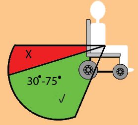
ENGLISH

          Wheelchair Components                                                                                                              EN
          We at SUNRISE MEDICAL have been awarded the ISO-9001 certificate, which affirms the quality of our products at every stage, from R &
          D to production. This products meet the requirements in accordance with EC guidelines. Options or accessories shown are available at extra
          cost.
          Rollstuhlkomponenten                                                                                                               de
          SUNRISE MEDICAL ist nach ISO 9001 zertifiziert und garantiert damit die Qualität unserer Produkte bei allen Entwicklungs- und
          Produktionsstufen dieses Rollstuhls. Dieses Produkt erfüllt die Anforderungen gemäß der EU-Richtlinien. Hier abgebildete Optionen oder
          Zubehörteile sind gegen Aufpreis erhältlich.

                                                                                                                                             fr
          SUNRISE MEDICAL est certifié ISO -9001, une norme qui garantit la qualité des produits à toutes les étapes, de la conception à la produc-
          tion, en passant par la recherche et le développement.Ce produit est conforme aux directives de la Communauté européenne.
          Les options ou accessoires illustrés sont disponibles moyennant un coût supplémentaire.
          Rolstoelonderdelen                                                                                                                 NL
          SUNRISE MEDICAL heeft het ISO 9001 certificaat toegekend gekregen, een bewijs van de kwaliteit van onze processen in elk stadium,
          vanaf het onderzoek en de ontwikkeling tot de productie.
          Deze producten voldoen aan de vereisten in overeenstemming met Europese richtlijnen. Getoonde opties en accessoires zijn tegen betaling
          verkrijgbaar.

          Componenti della carrozzina                                                                                                          it
          SUNRISE MEDICAL è certificata ISO 9001 a garanzia della qualità di tutti i suoi prodotti in ogni fase del processo, dalla ricerca e sviluppo sino
          alla produzione.
          Questo prodotto è conforme ai requisiti delle linee guida CE.Gli optional e gli accessori sono disponibili pagando un sovrapprezzo.

             2 RubiX2
Wheelchair: Rollstuhl: FAUTEUIL ROULANT :
1. Push handles 1. Schiebegriffe 1. POIGNEES DE POUSSÉE
2. Backrest upholstery 2. Rückenpolster 2. TOILE DE DOSSIER
ENGLISH
3. Sideguard 3. Seitenteil 3. PROTÈGE-VÊTEMENT
4. Seat sling 4. Sitzgurt 4. TOILE D› ASSISE
5. Footrest 5. FuSSstütze 5. REPOSE-PIED
6. Castors 6. Lenkrollen 6. ROUES AVANT
7. Footplates 7. FuSSplatte 7. PALETTES
8. Castor Fork 8. Lenkradgabel 8. FOURCHE
9. Folding Frame 9. Kreuzstrebe 9. CADRE PLIANT
10. Wheel locks 10. Bremse 10. FREINS
11. Rear Wheel 11. Hinterrad 11. ROUE ARRIÈRE
12. Arm Pad 12. Armauflage 12. MANCHETTE
1
2
12
3
11
4
5
6
10
7
9
8
CARROZZINA: ROLSTOEL:
1. MANOPOLE DI SPINTA 1. DUWHANDVATTEN
2. RIVESTIMENTO SCHIENALE 2. SPANBANDEN RUG
3. SPONDINA 3. ZIJKANTEN
4. RIVESTIMENTO 4. ZITBEKLEDING
DEL SEDILE 5. VOETSTEUN
5. APPOGGIAPIEDI 6. VOORWIELEN
6. RUOTE ANTERIORI 7. VOETENPLATEN
7. APPOGGIAPIEDI 8. VOORVORK
8. FORCELLA DELLA 9. VOUWFRAME
RUOTA ANTERIORE 10. REMMEN
9. TELAIO PIEGHEVOLE 11. ACHTERWIEL
10. FRENI 12. ARMKUSSEN
11. RUOTA POSTERIORE
12. IMBOTTITURA
DEL BRACCIOLO
RubiX2 3ENGLISH
1400 800 950 500
770 570 850 350
530 510 240 530
375 410 220 490
460 600 300
1400
410 380 240
770
850 340 +500 MAX
mm
800 280 -500
MIN
mm
10° 10° 10°
<
MAX
10° 10° 10°
<
MIN
0° 80° 118°
<
MAX
0° 74° 118°
<
MIN
8,4 17,3 170 2.0
8,4 14,9 125 ---
4 RubiX2A
ENGLISH
A
1
B C 2
B 3
1 1
2
2 1 4
3 2
3 5
375mm 6” 1A 375mm 24”
400mm 6” 2A 1B 1A 400mm 24” 1
425mm 6” 2B 2A 1B 425mm 24” 2
450mm 6” 3A 2B 450mm 24” 3
480mm 6” 3B 475mm 24” 4
500mm 24” 5
415mm 7” 2A 1A 525mm 24”
440mm 7” 2B 2A 1B
465mm 7” 3A 2B 375mm 22” 1
490mm 7” 3B 400mm 22” 2
425mm 22” 3
425mm 8” 2A 1A 450mm 22” 4
450mm 8” 2B 2A 1B 475mm 22” 5
480mm 8” 3A 2B 500mm 22”
505mm 8” 3B 525mm 22”
530mm 8” 3C
450mm 12”
45Nm 7Nm
7Nm
7Nm
7Nm
10Nm 10Nm
45Nm
7Nm
10Nm
7Nm
RubiX2 5Foreword Table of contents
Dear Customer, Wheelchair Components 2
We are very happy that you have decided in favour of a high-quality Foreword 6
SUNRISE MEDICAL product. Symbol legend 6
ENGLISH
Table of contents 6
This user’s manual will provide numerous tips and ideas so that Use 6
your new wheelchair can become a trustworthy and reliable partner Area of application 6
in your life. General safety notes and driving restrictions 7
We want you to be satisfied with our products and service. Sunrise
Warranty 8
Medical has been consistently working at continuously developing Transportability 9
its products, for this reason, changes can occur in our palette of Handling 11
products with regard to form, technology and equipment. Options – Step Tubes 11
Consequently, no claims can be construed from the data or pictures Options - Brakes 11
contained in this user’s manual. Options - Footplates 12
Options - Footplates 12
The management system of SUNRISE MEDICAL is certified to
ISO 9001, ISO 13485 and ISO 14001. Options - Castors 13
Options - Castor Adapter 13
As the manufacturer, SUNRISE MEDICAL, declares Options - Backrest 13
that the wheelchairs conform to the 93/42/EEC, Options – sideguard 14
amended by 2007/47/EC guideline. Options – Hemiplegic armrest 15
Options – Anti-Tip Tubes 15
In addition, they fulfil the performance requirements for the
"Crash Test" to ISO 7176-19 Options – Lap belt 15
. Options - Seat 16
Please contact your local, authorised SUNRISE MEDICAL dealer if Options – Depth Adjustable Seat Upholstery 16
you have any questions regarding the use, maintenance or safety Options – Seat depth 16
of your wheelchair. Options – Push handles 17
Options – Crutch holder 17
In case there is no authorised dealer in your area or you have any
questions, contact Sunrise Medical either in writing or by telephone
Options - Therapy table 17
(contact addresses can be found on the back page). Options - Stabilising Bar 17
Options – Headrests 17
Sunrise Medical Limited Options – Transit wheels 17
High Street Wollaston Options – One-hand operation 17
West Midlands DY8 4PS Name Plate 18
England
Tyres and mounting 18
Tel.: +44 (0) 1384446688
www.sunrisemedical.com Maintenance and care 18
Trouble shooting 19
Please keep a note of your local service agent’s address and Disposal / recycling of materials 19
telephone number in the space below. Technical Data 19
In the event of a breakdown, contact them and try to give all Torque 19
relevant details so they can help you quickly. Seat Height Adjustment 19
Use
Light-weight wheelchairs are exclusively for a user who is unable to
walk or has limited mobility, for their own personal use in- and
outdoor on dry, firm and level surface terrains (self propelling or
attendant push).
The maximum weight limit (includes both the user and any weight of
IMPORTANT: accessories fitted to the wheelchair) is marked on the serial number
DO NOT USE YOUR WHEELCHAIR UNTIL THIS label, which is affixed to the crossbar or stabiliser bar below the
MANUAL HAS BEEN READ AND UNDERSTOOD. seat.
Warranty can only be taken on if the product is used under the
Symbol legend specified conditions and for the intended purposes.
The intended lifetime of the wheelchair is 5 years. DO NOT use or fit
any 3rd party components to the wheelchair unless they are officially
DANGER! approved by Sunrise Medical.
Warning messages regarding possible risks of serious
accident or death. Area of application
WARNING! The variety of fitting variants as well as the modular design mean
Warning messages regarding possible risks of injury. that it can be used by those who cannot walk or have limited mobility
because of:
CAUTION! • Paralysis
Warning messages regarding possible technical damage. • Loss of extremity (leg amputation)
• Extremity defect deformity
NOTE: • Joint contractures/joint injuries
Information for operating the product. • Illnesses such as heart and circulation deficiencies, disturbance of
equilibrium or cachexia as well as for elderly people who still have
strength in the upper body.
When considering provision, please also note the body size, weight,
physical and psychological constitution, the age of the person, living
conditions and environment.
6 RubiX2General safety notes and driving restrictions
The engineering and construction of this wheelchair has been
• The wheel locks are not intended to stop your wheelchair in
designed to provide maximum safety. International safety standards
motion. They are only there to ensure that your wheelchair
currently in force have either been fulfilled or exceeded in parts.
does not begin rolling unintentionally. When you stop on
Nevertheless, users may put themselves at risk by improperly using
ENGLISH
uneven ground, you should always use the wheel locks to
their wheelchairs. For your own safety, the following rules must be
prevent unintended movement. Always apply both wheel locks;
strictly observed.
otherwise, your wheelchair could tip over.
Unprofessional or erroneous changes or adjustments increase the
risk of accident. As a wheelchair user, you are also part of the daily • Explore the effects of changing the centre of gravity on the
traffic on streets and pavements, just like anyone else. We would behaviour of the wheelchair in use, for example on inclines,
like to remind you that you are therefore also subject to any and all slopes, all gradients or when overcoming obstacles. Do this
traffic laws. with the secure aid of a helper.
Be careful during your first ride in this wheelchair. Get to know your
wheelchair. • With extreme settings (e.g. rear wheels in the most forward
Before each use, the following should be checked: position) and less than perfect posture, the wheelchair may tip
• Fixed axles or Quick-release axles on the rear wheels. over even on a level surface.
• Velcro on seats and backrests • Lean your upper body further forward when going up slopes
• Tyres, tyre pressure and wheel locks. and steps.
Before changing any of the adjustments of this wheelchair, it is
important to read the corresponding section of the user’s manual. • Lean your upper body further back when going down slopes
It is possible that potholes or uneven ground could cause this and steps. Never try to climb and descend a slope diagonally.
wheelchair to tip over, especially when riding uphill or downhill.
When riding forwards over a step or up an incline, the body should • Avoid using an escalator which may lead to serious injury in the
be leaning forward. event of a fall.
• Do not use the wheelchair on slopes more than 10°. The
DANGER! Dynamic safe slope is dependant on the chair configuration, the
NEVER exceed the maximum load of 125 kg, (XL=170 kg), for user users abilities and the style of riding. As the users abilities and
plus any items carried on the wheelchair. If you exceed the style of riding cannot be predetermined then the max safe slope
maximum load, this can lead to damage to the chair, or you may fall cannot be determined. Therefore this must be determined by
or tip over, lose control and may lead to serious injury of the user the user with the assistance of an attendant to prevent tipping.
and other people. It is strongly recommended that inexperienced users have Anti-
tips fitted.
• W
hen it is dark, please wear light clothing or clothing with
reflectors, so that you can be seen more easily. Make sure that • It is possible that potholes or uneven ground could cause this
the reflectors on the side and back of the wheelchair are clearly wheelchair to tip over, especially when riding uphill or downhill.
visible. • Do not use your wheelchair on muddy or icy ground.
• We would also recommend that you fit an active light. • Do not use your wheelchair where pedestrians are not allowed.
• T
o avoid falls and dangerous situations, you should first practice • To avoid hand injuries do not grab in between the spokes or
using your new wheelchair on level ground with good visibility. between the rear wheel and wheel lock when driving the
• When getting on or off the wheelchair, do not use the footboards. wheelchair.
• T
hese should be flipped up beforehand and swung to the outside • In particular when using lightweight metal handrims, fingers will
as far as possible. Always position yourself as close as possible to easily become hot when braking from a high speed or on long
the place where you wish to transfer to. inclines.
• O
nly use your wheelchair with care. For example, avoid travelling • Only attempt stairs with the help of an attendant. There is
against an obstacle without braking (step, kerb edge) or dropping equipment available to help you, e.g. climbing ramps or lifts,
down gaps. please use them. If there is no such equipment available, then
the wheelchair must be tipped and pushed, never carried, over
the steps (2 helpers). We recommend that users over 100 kg in
weight are not transferred in this way. In general, any anti-tip
tubes fitted must be set beforehand, so that they cannot touch
the steps, as otherwise this could lead to a serious tumble.
Afterwards the anti-tip tubes must be set back to their correct
position.
10° • Make sure that the attendant only holds the wheelchair using
securely mounted parts. Do not use removable parts (e.g. not
on the footrests or the side guards).
• When using the lifting ramp make sure that the anti-tip tubes
fitted are positioned outside the danger area.
• Secure your wheelchair on uneven ground or when transferring,
e.g. into a car, by using the brakes.
10°
RubiX2 7• The products shown and described in this manual may not
DANGER! be exactly the same in every detail as your own model.
• When using the lifting ramp make sure that the anti-tip tubes However, all instructions are still entirely relevant,
fitted are positioned outside the danger area. irrespective of detai differences.
• Secure your wheelchair on uneven ground or when • The manufacturer reserves the right to alter without notice
transferring, e.g. into a car, by using the brakes. any weights, measurements or other technical data shown
ENGLISH
in this manual. All figures, measurements and capacities
• If and whenever possible, during a journey in a specially fitted shown in this manual are approximate and do not constitute
vehicle for disabled people, vehicle occupants should use the specifications.
seats in the vehicle and the appropriate restraint system. This
is the only way to ensure that occupants will have the Lifetime
maximum protection if there is an accident. The expected lifetime of this product is 5 years provided that:
it is used in strict accordance with the intended use
• Depending on the diameter and setting of the castors, as well
all service and maintenance requirements are met.
as the centre of gravity setting of the wheelchair, the castors
may begin to wobble at high speeds. This can lead to castor
seizure and the wheelchair may tip over. Therefore, please
make sure that the castors are adjusted correctly (see the
Chapter "Castors").
• In particular, do not travel on an incline without brakes, travel
at a reduced speed. We recommend that novice users use Warranty
anti-tip tubes.
• Anti-tip tubes should prevent the chair tipping over Guarantee
backwards unintentionally. Under no circumstances should THIS IN NO WAY AFFECTS YOUR STATUTORY RIGHTS.
they take the place of transit wheels, and be used to Warranty conditions
transport a person in a wheelchair with the rear wheels 1) The repair or replacement must be carried out by an
removed. authorised Sunrise Medical dealer/service agent.
• When reaching for objects (which are in front of, to the side 2) To apply the warranty conditions, should your produc require
or behind the wheelchair) make sure that you do not lean too attention under these arrangements, notify the designated
far out of the wheelchair, as if you change the centre of Sunrise Medical service agent immediately giving full information
gravity there is a risk of tipping or rolling over. The hanging of about the nature of the difficulty. Should you be operating the
additional load (back pack or similar items) onto your chair product away from the locality of the designated Sunrise Medical
back posts can affect the rearward stability of your chair, service agent work under the "Warranty Conditions” will be
especially when used in combination with recliner backrests. carried out by any other service agent designated by the
This can cause the chair to tip backwards causing injury. manufacturer.
• For thigh amputees you must use anti-tip tubes. 3) Should any part of the wheelchair require repair or
• Before setting off, check that your tyre pressure is correct. replacement, as a result of a specific manufacturing or material
For rear wheels it should be at least 3.5 bar ( 350 kPa). The defect, within 24 months, (5 years on frame and cross-brace),
max. pressure is indicated on the tyre.The knee-lever brakes from the date on which the possession of the product was
will only work if there is sufficient tyre pressure and if the transferred to the original purchaser, and subject to it remaining
correct setting has been made (see the Chapter on within that ownership, the part or parts will be repaired or
"Brakes"). replaced completely free of charge if returned to the authorised
service agent.
• If the seat and back sling are damaged, you must replace NOTE: This guarantee is not transferable.
them immediately.
4) Any repaired or replaced part will benefit from these
• Be careful with fire, in particular with burning cigarettes. Seat arrangements for the balance of the warranty period applicable
and back slings can be set alight. to the wheelchair.
• If the wheelchair is subject to direct sunlight / cold
temperature for a long period of time, then parts of the 5) Parts replaced after the original warranty has expired are
wheelchair (e.g. frame, legrests, brakes and side guard) may covered for a further 12 months.
become hot (>41°C) / very cold (Transportability 7. The tie–down restraints should be attached as close as possible
at an angle of 45 degrees and tightened securely in accordance
with the manufacturer’s instructions.
DANGER!
There is a risk of serious injury or death if this if this advice is 8.Alterations or substitutions must not be made to the wheelchair
ignored! securement points or to structural and frame or components
ENGLISH
without consulting the manufacturer. Failure to do so will invalidate
Transportation of your wheelchair within a vehicle: the ability of a Sunrise Medical wheelchair to be transported within
a vehicle.
A wheelchair secured in a vehicle will not provide the equivalent
level of safety and security as a vehicle seating system. It is always
9. Both pelvic and upper torso restraint belts must be used to
recommended that the user transfers to the vehicle seating. It is
restrain the occupant to reduce the possibility of head and chest
recognised that this is not always practical for the user to be
impacts with the vehicle components and serious risk of injury to
transferred and in these circumstances, where the user must be
the user and other vehicle occupants. (Fig B) The upper torso
transported whilst in the wheelchair, the following advice must be
restraint belt should be mounted to the vehicle “B” pillar - failure to
followed:
do so will increase the risk of serious abdominal injuries to the user.
1. Confirm that the vehicle is suitably equipped to transport a
passenger in a wheelchair, and ensure the method of access/ 10. A head restraint suitable for transportation (see label on
egress is suitable for your wheelchair type. The vehicle should have headrest) must be fitted and suitably positioned at all times during
the floor strength to take the combined weight of the user, the wheel transportation.
chair and accessories.
11. Postural supports (lap straps, lap belts) should not be used or
2. Sufficient space should be available around the wheelchair to relied on for occupant restraint in a moving vehicle unless they are
enable clear access to attach, tighten and release the wheelchair labelled as meeting the requirements specified in ISO 7176-
and occupant tie down restraints and safety belts. 19:2001 or SAE J2249.
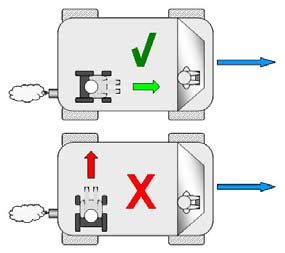
3.The occupied wheelchair must be located in a forward facing 12. The safety of the user during transportation depends upon the
position and secured by the wheelchair tie down and occupant diligence of the person securing the tie-down restraints and they
restraint straps (WTORS tie downs meeting the requirements of should have received appropriate instructions and/or training in
ISO 10542 or SAE J2249) in accordance with the WTORS their use.
manufacturer’s instructions.
13. Wherever possible remove and stow safely away from the
4. The wheelchair’s use in other positions within a vehicle has not wheelchair all auxiliary equipment, for example:
been tested e.g. transportation in a side facing position must not be Crutches, Loose cushions and Tray Tables.
carried out under any circumstances (Fig. A).
14. Articulating/elevating leg rest should not be used in the elevated
5. The wheelchair should be secured by a Tie Down Restraint position when the wheelchair and user are being transported and
system, conforming to ISO 10542 or SAE J2249 with non- the wheelchair is restrained using Wheelchair Transport and
adjustable front straps and adjustable rear straps, which typically Occupant Restraints.
use Karabiner clips/S hooks and tongue and buckle fittings. These
restraints generally comprise of 4 individual straps that are attached
15. Reclining backrests should be returned to an upright position.
to each corner of the wheelchair.
16. The manual brakes must be firmly applied.
6. The tie-down restraints should be fitted to the main frame of the
wheelchair as indicated in the diagram on the following page, and
not to any attachments or accessories, e.g. not around the spokes 17. Restraints should be mounted to the vehicle “B” pillar and
of wheels, brakes or footrests. should not be held away from the body by wheelchair components
such as armrest or wheels.
Fig.B
Fig.A
RubiX2 9Transportability Positioning of wheelchair tie down restraints
on wheelchair:
Occupant Restraints Instruction:
1. Location of the front and rear tie down labels (Fig. G-H-I).
1. The pelvic restraint belt must be worn low across the front of the
pelvis so that the angle of the pelvic belt is within the preferred zone 2. Position of the front, (Fig.G) and rear, (Fig.H-I), wheelchair tie
ENGLISH
of 30 to 75 degrees to the horizontal. down restraint and the tie down label.
A steeper (greater) angle within the preferred zone is desirable i.e.
3. Side view of tie down straps, (Fig.J)
closer to, but never exceeding 75degrees. (Fig C)
2. The upper torso restraint belt must fit over the shoulder and
across the chest as illustrated Fig d and e
Restraint belts must be adjusted as tightly as possible consistent
with user comfort.
Restraint belt webbing must not be twisted when in use. Fig.G
The upper torso restraint belt must fit over the shoulder and across
the shoulder as illustrated in Fig D and E.
3. The attachment points to the chair are the inner front side frame
just above the castor, and the rear side frame. The straps are fitted
around the side frames at the intersection of the horizontal and
vertical frame tubes. (See Figs G - K)
4. The tie down symbol (Fig F) on the wheelchair frame indicates the
position of the wheelchair restraint straps. The straps are then
tensioned after the front straps have been fitted to secure the
wheelchair.
Fig.H
Fig.C
Prefered Zone
Fig.D
Fig.I
Fig.E
Fig.J
Fig.F
10 RubiX2Handling Options – Step Tubes
Folding up Fig. 1 Step Tubes Fig. 5
First remove the seat cushion and the Tipping tubes are used by attendants
back seat shell from the wheelchair and to tip a wheelchair over an obstacle
flip up the (platform) footplate or the Simply step on the tube to push a
ENGLISH
individual footrests. Take hold of the wheelchair, for example, over a kerb
sling or the seat tubes in the middle, or step (Fig. 5).
from the back and pull upwards. The
wheelchair will then fold up. To fold CAUTION!
your wheelchair so that it is as small as
Sunrise Medical strongly recommends the use of a step tube on
possible, e.g., to put into a car, you can
transit wheeled models and also on any model where attendant use
remove the footrests (depending on the
is the predominant intended use, as damage to the backposts may
model). For this purpose, open the latch
occur if you pull back on them to tip the wheelchair, in order to
from the outside and swing the footrest to the side. Then the footrest
overcome obstacles.
only has to be drawn out of the receiver tube (Fig. 1).
Unfolding Fig. 2
Press down on the seat tube (see
figure). Your wheelchair is then unfolded.
Now snap the seat tubing into position in
the seat saddle. This can be facilitated
by slightly tipping your wheelchair, as Options - Brakes
this means that the weight is taken off
one of the rear wheels. Be careful not Wheel locks FIG. 6
to get your fingers caught in the Your wheelchair is equipped with
cross-tube assembly. Refit the seat two wheel locks. They are applied
and the back seat shell (Fig. 2). directly against the tyres. To engage,
press both brake levers forward
against the stops. To release the
locks, pull the levers back to their
Getting into your wheelchair independently original positions.
(Fig. 3)
• The wheelchair should be pushed up against Fig. 3 Braking power will decrease with:
a wall or solid piece of furniture; • Worn tyre tread
• The brakes should be on; • Tyre pressure that is too low
• The footplates should be hinged up; • Wet tyres FIG. 7
• The user can then lower himself into the chair; • Improperly adjusted wheel locks
• The footplates should then be pushed down
and the feet rested on them in front of the heel The wheel locks have not been
loops. designed to be used as brakes for a
moving wheelchair. The wheel locks
Getting out of your wheelchair should therefore never be used to
independently (Fig. 4) brake a moving wheelchair. Always
• The brakes should be on; use the hand-rims for braking. Make 20 mm
Fig. 4 sure that the gap between the tyres
• The hinged footplates should be hinged up;
• With one hand on each armrest, the person and wheel locks complies with given
should bend slightly forward to bring the body specifications. To readjust, loosen the screw and set the
weight to the front of the seat, and with both appropriate gap. Then re-tighten the screw (Fig. 6-7).
feet firmly on the ground, one foot well back,
CAUTION!
push up into the upright position.
After each adjustment of the rear wheels, check the wheel lock gap
WARNING! and re-adjust if necessary.
Mounting the wheel lock too close towards the wheel will result in a
• When standing, do not stand on the footplates or the higher effort to operate. This might cause the brake lever extension
wheelchair will tip up. It is easier and safer to get into your to break!
wheel chair if you turn the footplates up and out of the way or Leaning onto the brake lever extension while transferring will cause
take them off the wheelchair. the lever to break! Splashing water from tyres might cause the
• Always engage the wheel brakes when transfering in or out of wheel lock to malfunction.
the wheelchair.
Drum brakes
Drum brakes permit safe and Fig. 8
convenient braking for an attendant.
Quick-release axles on rear wheel They can also be set with the aid of a
The rear wheels are equipped with locking lever (1) to prevent rolling. The
Fig. 5
quick-release axles. The wheels lever must snap audibly into place.
can thus be fitted or removed without Drum brakes are not influenced by air
using tools. To remove a wheel, simply pressure inside the tyres. Your
depress the quick-release button on wheelchair cannot be moved when the
the axle (1) and pull the wheel off the drum brakes are set (Fig.8).
axle (Fig. 5). 1
CAUTION!
CAUTION!
Drum brakes must only be adjusted by authorised dealers.
Hold the quick-release button on the
axle depressed when inserting the
axle into the frame to mount the rear
1
wheels. Release the button to lock the
wheel in place. The quick-release button should snap back to its
original position
RubiX2 11One-hand operation Fig.9 Options - Footplates
Your wheelchair is equipped with
two sets of wheel locks that can be Footrests and Latch FIG.13
operated from either the left or the The legrests can be swung inwards 1
right side. They are applied directly under the seat sling or outwards. When
against the tyres. To engage, push fitting the legrests, the footrests must be
ENGLISH
the brake lever forward against the pointing inwards or outwards. Then rotate
stops (Fig. 9). To release the locks, the legrest inwards, until it locks into
pull the lever back to its original place. To remove, pull the lever (1),
position. swing the footplate inwards or outwards
and then lift the legrest out. Make sure
• Braking power will decrease with: that the legrest is locked into place
• Worn tyre tread correctly, (Fig 13).
Fig.10
• Tyre pressure that is too low
• Wet tyres CAUTION!
• Improperly adjusted wheel locks.
• The legrests must not be used to lift or to carry the wheelchair.
The wheel locks have not been
designed to be used as brakes for a • When getting on or off the wheelchair, do not use the footboards.
moving wheelchair. The wheel locks These should be flipped up beforehand or the footrest should be
should therefore never be used to swung to the outside as far as possible.
brake a moving wheelchair. Always use the hand-rims for braking.
Make sure that the gap between the tyres and wheel locks complies Option Elevating legrest
with given specifications. To re-adjust, loosen the screw and set the FIG.14
(Fig 14-16)
appropriate gap. Then re-tighten the screw (see the page on torque) To remove, pull the lever (1), swing the
(Fig. 10). footplate outwards and then lift the 1
legrest out.
CAUTION:
After each adjustment of the rear wheels, check the wheel lock gap Height Adjustment:
and re-adjust if necessary. The lower leg length can be adjusted
infinitely by releasing the screw (2).
Mounting the wheel lock too close towards the wheel will result in a Adjust the suitable height and tighten the
higher effort to operate. This might cause the brake lever extension screw again.
to break! Leaning onto the brake lever extension while transferring
will cause the lever to break! Splashing water from tyres might CAUTION!
FIG.15
cause the wheel lock to malfunction.
The distance between the footplate
and the ground must be at least 40
mm.
ANGLE ADJUSTMENT:
Options - Footplates
Press the lever (3) downward with one
Footplates: Fig.11 hand while supporting the legrest with
The footplates can be flipped up to the other hand to take the load off. When
make it easier to transfer to/from the a suitable angle is achieved, let go of the
chair. lever and the legrest will lock into one of
Lower leg length: the preset positions.
For users with longer legs, the leg 2
support can be lowered to the
appropriate level by using the screws
(1). Loosen the screws, push the 1 FIG.16
3
tubes to the desired position and
then re-tighten the screws (see
section on torque). There must
always be a minimum gap of 2.5 cm between the footplates and the
ground, (Fig.11).
Angle-adjustable Fig.12
footboard
This can be adjusted to alter the
angle to the ground. Release
screw, pull it inwards, set the
desired angle and then push it
on. After making the adjustment,
re-tighten the screw.
Make sure that after any
adjustment work, all screws are tightened correctly (see the page 5
torque).
Ensure that you maintain the minimum gap to the floor (2.5 cm) (Fig.
12).
12 RubiX2Adjusting the calf pad Options – Castor adapter
(Fig 17).
FIG.17
The calf pad can be adjusted as
follows: NOTE:
Height: Open bolt (4) and move the 5 You can change the angle of the castor axle by altering the position
clamping piece to the desired of the castor/rear wheel. This should always be approx. 90°.
ENGLISH
position. By rotating the clamping
piece also the angle can be Adjusting the castor axle angle:
adjusted.
Depth: Open bolt (5) and move the Release the screws (1), pull the castor adaptor outwards, set a 90°
calf pad into the desired position. angle and then re-tighten the screws (Fig. 20-21).
Width: Open bolt (5) and position the 4
spacers (6) behind the pad, to get 6 Fig.20 Fig.21
the desired position.
WARNING!
• Keep hands clear of the adjustable mechanism between the
frame and the movable parts of the foot rest, while elevating or
lowering the footrest.
90°
• Always make sure that the fasteners are secure.
• The foot rests must not be used to lift or to carry the
1
wheelchair.
CAUTION!
• Risk of trapping fingers! When moving the foot rest up or
down, do not put your fingers in the adjusting mechanism
between the moving parts of the foot rest. The castor axle angle must be set the same on both sides (check by
marking).
AMPUTEE SUPPORT FIG.19 Fig.22
(Fig.18). Horizontal axle position
The Amputee Support can be
adjusted in every direction as The axle plate can be adjusted
required. forwards to give greater
manoeuvrability or to the rear to give
greater stability (Fig. 22).
The larger the wheelbase the greater
the security against your wheelchair
tipping over
Options - Backrest
Options - Castors
Height-adjustable Fig.23
Castors, castor plates, forks backrest 1
The wheelchair may veer slightly to the right or left, or the castors The height of the backrest can be set
may wobble. This may be caused by the following: to 2 or 3 different positions
(depending on the model) (41 cm,
• Forward and/or reverse wheel motion has not been set properly. 43.5 cm and 46 cm). Release and
• The castor angle has not been set correctly. remove the bolts (1)+(2), and push
• Castor and/or rear wheel air pressure is incorrect; the wheels do the backrest tube to the desired
not turn smoothly. position. Tighten up the bolts again
(Fig. 23).
The wheelchair will not move in a straight line if the castors have
not been properly adjusted. Castors should always be adjusted by
an authorised dealer. The wheel locks must be checked every time
Adjustable backrest Fig.24
the rear wheel position has been altered.
angle
Options - Castor Adapter
The angle of the backrest can be set
to 6 different positions (-5° forwards,
The seat height is determined by the Fig.19 0°, 5°, 10°, 15° and 20° backwards).
castor and rear wheel position. The To adjust the angle, remove the
seat height can be adjusted by screw (1), set the desired angle and
altering the position of the rear then re-tighten the screw (Fig. 24).
wheels and the castors and by using 1
spacers, (Fig.19).
Adjustable backrest
CAUTION! angle Fig.25
(7° - 30°)
After adjusting the seat height, all
screws must be re-tightened and the By pulling both levers together (1),
wheel lock must be readjusted. you can release the backrest and
then move it to the desired position.
On releasing the two levers (1) the 1
backrest will automatically lock into
place (Fig. 25).
RubiX2 13Trunk support
CAUTION! The trunk support can be adjusted in
Fig.30
• It is recommended that the angle-adjustable backrest is used angle, depth and height. It can be
in conjunction with the wheelbase extension. swing away by lifting it
upwards.
• It is recommended that the angle-adjustable backrest is used • Depth adjustment: Remove the 2
ENGLISH
in conjunction with anti-tip tubes (maximum ground clearance screws and fit the trunk support in the
3 - 5 cm). new position. Finally tighten screws
again.
• We recommend that the angle-adjustable backrest is used in
• Angle adjustment: Open screw, set
conjunction with a stabilising bar.
the trunk support into the wished
Angle and tighten the screw again. (Fig.30)
Half folding back Fig.26 • Height adjustment: Remove the fixing screws of the bracket and
Unfolding the backrest: move the bracket into the wished position. Finally tighten the
To put the backrest in the upright screws again.
position, push the handles upwards
and forwards until they lock in,
(Fig.26).
WARNING! Options – sideguard
Keep fingers and other items away
from the folding mechanism when Standard side guard, Fig.31
2
the backrest is being folded to flip-up, removable
prevent injury or damage to property. with short or long 1
armrests
Folding the backrest: Fig.27
The backrest can be folded to make The sideguard with rounded off front
storage of the wheelchair easier, edges will allow you to get up close to
(Fig.27). a table. To flip the armrest up, push
the lever (1), so that the sideguard is
CAUTION! released (Fig.31 + 32).
Do not operate under load as this
may cause lever to break. The height of the armrest (2) can Fig.32
be adjusted by fitting the
To fold the backrest, stand behind spacer bracket in various positions.
the wheelchair, press the two small To do this release the screws, move 3
levers (Fig. 27 - 28) positioned on each side of the backrest (just the spacer bracket and re-tighten the
above the armrests). Fold the backrest down. screws. The length of the armrest can
be adjusted by releasing the screws
Adjustable back-sling Fig.28 (3), then move the armrest to the
desired position and re-tighten the
The adjustable back-sling screws (Fig.33).
can be adjusted for tension
by using several straps (Fig. 28). CAUTION:
CAUTION! • N
either the sideguards nor the armrests are to be used for lifting
or carrying the wheelchair.
Do not pull the tension belt too tight, • Take care of your fingers when adjusting the arm pad height.
otherwise this could interfere with the
folding mechanism of the chair. Side guard, flip-up, removable with short or
long armrests, height-adjustable
Comfort back The armrest can be height-adjusted as follows.
The comfort back permits Fig.29
Move the lever downwards and move
comfortable long seating with lateral the armrest to the desired height. Fig.33
support. Release the lever and press the 1
The complete can be removed by armrest downwards until you hear it 2
lifting up and pushing forward. The click into place. Always check that the
cushion is fixed by velcro and can be side guards are correctly in
removed as well. The cover is place.
washable.(Fig. 29) To flip the armrest up, push the lever
(1) so that the sideguard is released.
You can adjust the length of the armrest by releasing the screws (2)
push the armrest to the desired position and then re-tighten the
screws (Fig.33).
CAUTION:
• N either the sideguards nor the armrests are to be used for lifting
or carrying the wheelchair.
• When using a 24" rear wheel the armpad must be moved one
level up.
14 RubiX2Height-adjustable armrests Fig.34 Options – Lap belt
1
To adjust the height, pull the lever (1) and
push the armrest to the desired height. WARNING!
Afterwards make sure that the lever (1)
locks back into position. Removing the 2 Before using your wheelchair ensure the seat belt is worn and
correctly adjusted before use.
ENGLISH
armrest is carried out in the same way.
To remove the sideguard completely, push The lap belt is fitted to the wheelchair as shown in the illustrations.
the lever (2). When fitting the sideguard, the lever (2) must also be The seat belt comprises 2 halves. They are fitted using the existing
pulled. seat stay retaining bolt fitted through the eyelet on the belt. The belt
Always make sure that the sideguard locks into position is routed under the rear of the side panel. (Fig. 37)
correctly in the receiver. (Fig. 34) Adjust the belt position so buckles are in the centre of the seat. (Fig.
38)
Options – Hemiplegic armrest Fig.37 Fig.38
Hemiplegic armrest
The hemiplegic armrest can be Fig.35
adjusted both in length and angle.
You can adjust the length by
pushing the armrest after having
loosened the 2 rotary screws (1). 1
To adjust the angle, open the
release lever (2) and rotate the
armrest to the desired position, 2
then tighten it again (Fig. 35).
Options – Anti-Tip Tubes Adjust lap belt to suit the user’s needs as follows:
Anti-Tip Tubes Fig.36 To increase the belt To reduce the belt
Anti-tip tubes provide additional
safety for inexperienced users when length lenght
they are still learning how to operate
their wheelchair. They prevent a
wheelchair from tipping over
backwards. The anti tip tube should
be inserted into the frame tube until Type B Type B Type B
the first of the two spring buttons
enters the first hole in the frame tube,
(Fig.36).
Feed free belt Feed free belt back Ensure belt is not
WARNING! through slide adjust- through male buckle looped at male
ers and male buckle and slide adjusters. buckle.
Incorrect setup of the anti-tips will increase the risk of a rearwards to provide more belt
tip. You must swing the anti-tips upwards when going up or down length.
large obstacles, (such as a kerb), to prevent them from touching the
ground, then rotate them back down to the normal position.
NOTE: Do not insert both buttons of the anti tip tube into the frame
tube as this could damage the anti Tipp and cause a loss of
effectiveness. By pushing on the Second exposed release button,
the safety wheels can be set upwards or removed. There must
always be a gap of between 3 cm and 5 cm between the tube and
the ground. You must swing the safety wheels upwards when going
up and down large obstacles (such as a kerb) to prevent them from
touching the ground. Then rotate the safety wheels back down to
the normal position (Fig. 36).
WARNING!
Incorrect set up of the anti tips will increase the risk of a rearwards
tip.
RubiX2 15Options – Lap belt Options - Seat
When fastened check space between the lap belt and user, when Standard seat sling
correctly adjusted it should not be possible to insert more than the The sling is equipped with a Velcro Fig.41
flat of the hand between the lap belt and the user. (Fig. 39) fastener on one side, this permits
stepless adjustment of the sling. To
ENGLISH
Generally the Lap Belt should be fixed so that the straps sit at an adjust the sling, fold the chair up.
angle of approximately 45°, and when correctly adjusted should not Then pull the front cover caps
allow user to slip down in the seat. forwards out of the frame. The sling
(Fig. 40) can be pulled off the frame. Undo the
Velcro fastener and adjust the sling.
Fig.39 Fig.40 Reverse this procedure to refit the
sling (Fig. 41).
CAUTION!
• For proper safety, at least 50 % of the Velcro surfaces must
be in contact with each other at all times.
• The sling must not be pulled too tight, as otherwise this
could interfere with the folding mechanism of the chair.
Seat depth.
Comfort seat
The comfort seat permits comfortable long seating due to
the wooden base and the anatomically shaped cushion.
Options – Depth Adjustable Seat Upholstery
Fig.42
depth Adjustable Seat
To fasten buckle: To release belt: Upholstery
Firmly push male buckle into Press exposed sides of male You can easily alter the seat depth
female buckle. buckle and push towards centre by using the Velcro fastener on the
/ push the press button of the seat sling.
female buckle whilst gently pull- Separate sling (1) from sling, set the
ing apart. desiredposition and then
push both slings back together, one
on top of each other (Fig. 42).
Advice to client
DANGER! Options – Seat depth
• Do not rely on the lap belt only when the wheelchair and
occupant are transported in a vehicle, use the separate Seat Depth
occupant lap and diagonal restraints provided in the vehicle. By removing the clips (1), the cross-brace unit (2) can be pushed
along the frame, which then alters the seat depth (depending on the
• Before use we recommend that the lap belt be checked to position of the back tubes).
ensure that it is adjusted correctly, free from any obstruction or
adverse wear and that the buckle engages securely. Make sure that the clips (1) snap into the frame holes provided.
• Failure to make sure that the lap belt is secure and adjusted To keep the frame as compact as possible, the seat depth can also
prior to use could cause serious injury to the user. e.g. too be adjusted by using the back tubes (41 – 51 cm in steps of 2.5 cm).
loose a strap may allow the user to slip down in the chair and To do this remove the screws (1 and 2) on the back tube bracket.
risk suffocation. Remove the wheels and the armrests and check that the cross-
brace is in the desired position (push the cross-brace as described
Maintenance: above). Move the back tubes to the desired position and re-tighten
all screws. Move the receiver tube for the armrests to the desired
Check lap belt and securing components at regular intervals for any position (Fig. 43).
sign of fraying or damage. Replace if necessary. Clean the lap belt
with warm soapy water and allow it to dry. Fig.43
DANGER!
The lap belt should be adjusted to suit the end user as detailed
above Sunrise Medical also recommend that the length and fit of
the belt is checked on a regular basis to reduce the risk of the end
user inadvertently re-adjusting the belt to an excessive length.
If in doubt about the use and operation of the seat belt then ask
your healthcare professional, wheelchair dealer, carer or attendant
2
for assistance.
1
16 RubiX2Options – Push handles Folding stabilising bar Fig.49
This bar is used to stabilise the
Height-adjustable push backrest. To be able to fold the
Fig.44
handles wheelchair, the stabilising bar must be
These handles are secured with pins pushed downwards in the middle (1).
to prevent them from sliding out To completely unfold the wheelchair,
ENGLISH
unintentionally. By releasing the the carrying handle (2) must be pulled
release lever (1) you can adjust the upwards, (Fig.49).
push handles to a height which suits 1
you. After any adjustment to the
height of the push handles, pull the Options – Headrests
release lever (1) until it is tight (Fig. 44).
Fig.50
CAUTION: Headrests
The headrest can be raised and moved
If the lever is not secure, injuries could result when lifting over both forwards and backwards. To do this,
obstacles. simply loosen the screw, adjust the
headrest to the desired position, and
tighten the screw (see the section on
torque) (Fig. 50).
Options – Crutch holder
Crutch Holder Fig.45
This device permits crutches to be Fig.51
transported directly on a wheelchair. It has a Comfort headrest
Velcro loop to fasten crutches or other aids For adjusting the height open knob
(Fig. 45). and position the headrest in the
desired height. Finally tighten the
CAUTION: knob again, (Fig.51).
Never try to use or even remove the
crutches or other aids while moving.
Options – Transit wheels
Transit wheels
Options - Therapy table Transit wheels should be used wherever your wheelchair would be
too wide if the rear wheels were used (e.g., in
Therapy table Fig.46 airplanes, buses, etc.). After the rear wheels have been Fig.52
The tray provides a flat surface for removed with the aid of the quick-release axles, the
most activities. Before using a tray, it transit wheels can immediately be used to continue
first has to be adjusted to the width of riding. The transit wheels are mounted so that they
the seat by an authorised dealer. The are approx. 3 centimeters above the ground when not
user must be sitting in the wheelchair in use. They are thus out of the way when riding,
during this adjustment (Fig. 46). transporting or when tipping to pass over obstacles
(e.g., kerbs, steps, etc.) (Fig. 52).
CAUTION:
Options - Stabilising Bar
Your wheelchair does not have any wheel locks when
Recliner STABILISING BAR Fig.47 the transit wheels are being used.
Open star-knob (1) and swing the
stabilising bar (2) out of the way
before folding the chair.
To reinstate the wheelchair, reverse 2
the above procedure, (Fig.47).
Options – One-hand operation
DANGER! One-hand operation Fig.53
To move the wheelchair in a straight
• B
efore using the wheelchair
ensure that the stabiliser bar and
1 line, both hand wheels must be
operated. If the wheelchair is to be
star-knobs are in place and are
folded up, remove the pull-off bar by
tightened correctly.
pushing it inwards (Fig. 53).
• Never use the stabiliser bar to lift the chair!
CAUTION:
To avoid injury, always make sure
that all connections are firmly in place.
Swingaway stabilising bar
Fig.48
This bar is used to stabilise the
backrest. To be able to fold the
wheelchair, the release lever (1)
must be pushed inwards and the
stabilising bar must be flipped
downwards. When unfolding the
wheelchair, please make sure that 1
the stabilising bar is locked into
position (Fig. 48).
RubiX2 17Name Plate Tyres and mounting
Nameplates Tyres and mounting
Solid tyres are standard.
The nameplate is located on either the cross-tube assembly or the With pneumatic tyres make sure that you maintain the correct tyre
ENGLISH
transverse frame tube, as well as on a label in the owner’s manual. pressure, as this can have an effect on wheelchair performance. If
The nameplate indicates the exact model designation and other the tyre pressure is too low, rolling resistance will increase, requiring
technical specifications. Please provide the following pieces of more effort to move the chair forward. Low tyre pressure also has a
information whenever you have to order replacement parts or to file negative impact on manoeuvrability. If the tyre pressure is too high,
a claim: the tyre could burst. The correct pressure for a given tyre is printed
on the surface of the tyre itself.
SAMPLE Tyres can be mounted the same way as an ordinary bicycle tyre.
Before installing a new inner tube, you should always make sure
that the base of the rim and the interior of the tyre are free of foreign
objects. Check the pressure after mounting or repairing a tyre. It is
critical to your safety and to the wheelchair’s performance that
regulation air pressure be maintained and that tyres be in good
condition.
RubiX2
Maintenance and care
Safety Check:
As the user you will be the first person to notice any possible
defects. We therefore recommend that before each use, you check
RubiX2 the following:
Product Name/SKU Number.
The tyre pressure is correct.
Maximum safe slope with anti-tips fitted, The brakes work correctly.
Depends on wheelchair setting, posture and All removable parts are securely fastened (e.g. armrests, footrest
physical capabilities of the user. hangers, quick-release axles ...).
If there is any damage/defect, please contact your authorised dealer.
Seat width.
Maintenance:
Depth (maximum).
Check the tyre pressure at regular intervals.
Check all tyres for wear and damage at regular intervals, at least
Load Maximum. annually. Change the tyres as soon as there is any sign of damage
or wear.
Check the seat and back sling for wear and damage at regular
CE Mark
intervals, at least annually. Change these items as soon as there is
any sign of damage or wear.
User's Guide. Check all frame and backrest components for wear and damage at
regular intervals, at least annually. Change these items as soon as
there is any sign of damage or wear.
Check the brakes for wear and damage at regular intervals, at least
Crash Tested annually. Check that they are working properly and are easy to use.
Change the brakes as soon as there is any sign of damage or wear.
Check to make sure all bolts are secure (see the section on torque)
Date of manufacture. at regular intervals, at least annually. All screws which are critical to
using the wheelchair safely have safety nuts. Safety nuts should
only be used once and should be replaced after use.
Serial number.
Note: If torque settings are given, then we strongly recommend
Due to our policy of continuous improvement in the design of our that you use a torque measuring device, in order to check that you
wheelchairs, product specifications may vary slightly from the have tightened to the correct torque.
examples illustrated. All weight/dimensions and performance data Please use only mild household cleaners when your wheelchair is
are approximate and provided solely for guidance. dirty. Use only soap and water when cleaning the seat upholstery
Sunrise Medical complies with the EU Medical Devices Directive and lap belt.
93/42/EEC Depending on the frequency and type of use, we recommend taking
your wheelchair to your authorised dealer regularly, but at least
All wheelchairs must be used in accordance with the within a year, to have it maintained by trained personnel.
manufacturer’s guidelines.
CAUTION!
Sunrise Medical GmbH & Co.KG
Kahlbachring 2-4
Sand, salt and sea water can damage the bearings of the front and
69254 Malsch/Heidelberg
rear wheels. Clean and dry the wheelchair carefully, after they have
Germany
been exposed to these elements.
Tel.: +49 (0) 7253/980-400
Fax: +49 (0) 7253/980-111
www.sunrisemedical.com
18 RubiX2Hygiene when being reused: Technical Data
When the chair is to be reused, it should be prepared carefully, and
be wiped and treated with spray disinfectant on all surfaces which Overall width:
could come into contact with the user. • With standard wheels including handrims, close mount:
RubiX2: SW +19 cm
If you need to do this quickly, you must use a liquid, alcohol-based
ENGLISH
disinfectant suitable for medical products and devices. • With drum brake wheels including handrims, close mounted:
Please pay attention to the manufacturer’s instructions of the RubiX2: SW +21 cm
disinfectant you are using. Folded dimensions:
• With standard wheels:
RubiX2: 30 cm
• Without standard wheels:
Trouble shooting RubiX2: 24 cm
Wheelchair pulls to one side
• Check tyre pressure Maximum load:
• Check to make sure wheel turns easily (bearings, axle) • RubiX2 up to a load of 125 kg
• Check the castor angle • Reinforced version RubiX2 XL up to a load of 170 kg
• Check to make sure both castors are making proper contact with
the ground Weights in kg:
• Transportation (without footrest, wheels, sideguard) 8.4 kg
Castors begin to wobble • Transportation RubiX2 XL , (without footrest,
• Check the castor angle wheels, sideguard): 11.4 kg
• Check to make sure all bolts are secure; tighten if necessary (see
the section on torque) • Footrest (unit): 0.8 kg
• Check to make sure both castors are making proper contact with • Standard sideguard (unit): 0.8 kg
the ground • 24" rear wheels (solid) (pair): 3.8 kg
Wheelchair squeaks and rattles Maximum occupant mass (test dummy mass): 125 kg, (XL= 170kg)
• Check to make sure all bolts are secure; tighten if necessary (see
the section on torque) Also see page 4
• Apply small amount of lubrication to spots where movable parts
come in contact with one another In Accordance with EN12183: 2009 all there listed parts (seat - back
upholstery, arm pad, side panel...) are fire resistant as per EN1021-2 .
Wheelchair begins to wobble
The Dynamic safe slope is dependant on the chair configuration, the
• Check angle at which castors are set
users abilities and the style of riding. As the users abilities and style of
• Check tyre pressure
riding cannot be predetermined then the max safe slope cannot be
• Check to see if rear wheels are adjusted differently
determined. Therefore this must be determined by the user with the
assistance of an attendant to prevent tipping. It is strongly
recommended that inexperienced users have Ant-tips fitted.
The wheelchair conforms to the following standards:
Disposal / recycling of materials a) Requirements and test methods for static, impact and fatigue
strengths (ISO 7176-8)
NOTE: If the wheelchair has been supplied to you free of charge it b) Requirements for resistance to ignition in accordance with ISO
may not belong to you. If it is no longer required follow any 7176-16 (EN 1021-1)
instructions given by the organisation issuing the wheelchair in order
that it may be returned to them.
The following information describes the materials used in the Torque
wheelchair in relation to the disposal or re-cycling of the wheelchair
and its packaging. Unless otherwise advised, the torque for M6 screws is 7 Nm.
Specific waste disposal or recycling regulations may be in force Please refer to page 5 for detaials
locally and these should be taken into consideration when disposal
arrangements are made. (This may include the cleaning or
de-contamination of the wheelchair before disposal).
Aluminium: Castor forks, wheels, side frames, armrests, frame, leg Seat Height Adjustment
rests, push handles
Steel: Fasteners, QR axle Please refer to the table on page 5.
Plastic: Handgrips, tube plugs, castor wheels, footplates, armpads
and 12” wheel/tyre
Packaging: Low density polythene bag, cardboard box
Upholstery: Woven polyester with PVC coatings and expanded
combustion modified foam.
Disposal or recycling should be done through a licensed agent or
authorised place of disposal. Alternatively your wheelchair may be
returned to your dealer for disposal.
RubiX2 19Vous pouvez aussi lire


