Planification et réalisation de manoeuvres de réorientation de robots en chute libre - Mémoire Mark Charlet Maîtrise en génie mécanique - avec mémoire
←
→
Transcription du contenu de la page
Si votre navigateur ne rend pas la page correctement, lisez s'il vous plaît le contenu de la page ci-dessous
Planification et réalisation de manoeuvres de
    réorientation de robots en chute libre

                      Mémoire

                    Mark Charlet

      Maîtrise en génie mécanique - avec mémoire
                Maître ès sciences (M. Sc.)

                   Québec, Canada

                 © Mark Charlet, 2022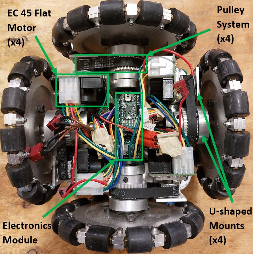
Planification et réalisation de manoeuvres de
    réorientation de robots en chute libre

                        Mémoire

                      Mark Charlet

                   Sous la direction de:

         Clément Gosselin, directeur de recherche
Résumé

Ce mémoire présente des manoeuvres de réorientation appliquées à un robot articulé et à un
robot mobile en chute libre. Ces manoeuvres, initialement inspirées du phénomène du chat
qui atterrit toujours sur ses pattes, sont aussi attribuées à d’autres animaux, tels que cer-
tains reptiles et même les humains dans le contexte de certains sports. Les manoeuvres de
réorientation ont aussi des applications dans le domaine de la robotique. En effet, de tels ma-
noeuvres s’avèrent utiles pour le contrôle de pose d’atterrissage pour des robots susceptibles
aux chutes, comme les robots sauteurs ou les robots de secours qui doivent être déployés dans
des environnements dangereux et difficiles à parcourir. Dans cette optique, le travail présenté
dans ce mémoire vise à développer et démontrer des manoeuvres de réorientation permettant
une réorientation rapide (redressement de 180 degrés — le pire cas possible — dans le temps
d’une chute d’un mètre) et multiaxe. Tout d’abord, une architecture articulée ainsi que deux
manoeuvres de réorientation sont conçues afin d’atteindre les capacités de réorientation visées
et les performances de cette architecture sont testées en simulation. Les résultats obtenus dé-
montrent que l’architecture proposée est capable de se réorienter selon plusieurs axes, mais
n’atteint pas les performances visées en termes de vitesse de réorientation. Par la suite, une
architecture mobile omnidirectionnelle et compacte est conçue afin d’adresser les limitations
de la première architecture. Un prototype de cette architecture est développé et permet d’ef-
fectuer une réorientation de 179 degrés selon son axe de tangage en 0.44 secondes tout en
conservant sa capacité de se redresser selon plusieurs axes. Les performances de réorientation
visées sont alors atteintes avec ce deuxième prototype. Enfin, une méthode de fusion de don-
nées par filtre de Kalman étendu servant à estimer l’orientation d’une plateforme en apesanteur
est explicitée et est validée dans des conditions contrôlées. Ces résultats démontrent l’utilité
de telles méthodes de fusion de données pour implémenter la planification automatique des
manoeuvres de réorientation dans les itérations futures du prototype développé.

                                               ii
Abstract

This thesis explores the application of reorientation manoeuvres to an articulated and a mobile
robot architecture. These manoeuvres are often attributed to cats that are said to always land
on their feet, but have also been observed in other animals and used by humans in certain
sports. However, these manoeuvres are more than just a curiosity and have seen some use in the
field of robotics. Indeed, reorientation manoeuvres are used for orientation control in falling
robots, such as rescue robots deployed in dangerous environments, and in jumping robots.
With such applications in mind, this thesis aims to develop and demonstrate fast (180-degree
reorientation about one axis — the worst-case scenario — within the time of a one-metre
fall), multi-axis reorientation manoeuvres. Firstly, an articulated architecture, along with two
different manoeuvres, are designed in order to attain the desired reorientation capabilities
and are tested in simulated conditions. The results obtained show that, although multi-axis
reorientation is achieved, the required motor torques to reach the desired reorientation speeds
are not feasible for the proposed architecture. Secondly, an omnidirectional mobile robot
architecture is designed to address the limitations of the first architecture. A prototype of
this mobile architecture is developed and is used to demonstrate a reorientation of 179 degrees
about the pitch axis in 0.44 seconds as well as a reorientation about multiple axes. Therefore,
with this prototype, the desired reorientation capabilities are achieved. Finally, the use of
sensor fusion methods based on extended Kalman filtering in the context of estimation of the
orientation of a free-floating platform is studied. The results obtained from this study support
the viability of using such methods for on-board trajectory planning in future iterations of the
developed prototype.

                                               iii
Table des matières

Résumé                                                                                                             ii

Abstract                                                                                                          iii

Table des matières                                                                                                iv

Liste des tableaux                                                                                                vi

Liste des figures                                                                                                vii

Remerciements                                                                                                     xi

Avant-propos                                                                                                     xiii

Introduction                                                                                                       1

1 Reorientation of Free-Falling Legged Robots                                                                      3
  1.1 Résumé . . . . . . . . . . . . . . . . . . . . . . . . . . . .     .   .   .   .   .   .   .   .   .   .     3
  1.2 Abstract . . . . . . . . . . . . . . . . . . . . . . . . . . . .   .   .   .   .   .   .   .   .   .   .     3
  1.3 Introduction . . . . . . . . . . . . . . . . . . . . . . . . . .   .   .   .   .   .   .   .   .   .   .     4
  1.4 Kinematic and Dynamic Analysis of Free-Floating Robots             .   .   .   .   .   .   .   .   .   .     5
  1.5 Proposed Architecture and Reorientation Manoeuvres . .             .   .   .   .   .   .   .   .   .   .     9
  1.6 Simulated Results and Discussion . . . . . . . . . . . . . .       .   .   .   .   .   .   .   .   .   .    12
  1.7 Conclusion . . . . . . . . . . . . . . . . . . . . . . . . . .     .   .   .   .   .   .   .   .   .   .    17

2 Multi-axis Reorientation of a Free-falling Omnidirectionnal                        Wheeled
  Robot                                                                                                           20
  2.1 Préambule . . . . . . . . . . . . . . . . . . . . . . . . . . . . . .          .   .   .   .   .   .   .    20
  2.2 Résumé . . . . . . . . . . . . . . . . . . . . . . . . . . . . . . .           .   .   .   .   .   .   .    22
  2.3 Abstract . . . . . . . . . . . . . . . . . . . . . . . . . . . . . . .         .   .   .   .   .   .   .    22
  2.4 Introduction . . . . . . . . . . . . . . . . . . . . . . . . . . . . .         .   .   .   .   .   .   .    22
  2.5 Proposed Architecture . . . . . . . . . . . . . . . . . . . . . . .            .   .   .   .   .   .   .    24
  2.6 Prototype . . . . . . . . . . . . . . . . . . . . . . . . . . . . . .          .   .   .   .   .   .   .    26
  2.7 Results and Discussion . . . . . . . . . . . . . . . . . . . . . . .           .   .   .   .   .   .   .    29
  2.8 Conclusion . . . . . . . . . . . . . . . . . . . . . . . . . . . . .           .   .   .   .   .   .   .    31
  2.9 Appendix A : Free Roam Kinematics . . . . . . . . . . . . . . .                .   .   .   .   .   .   .    32

3 Détails de conception du prototype mobile                                                                       34
  3.1 Introduction . . . . . . . . . . . . . . . . . . . . . . . . . . . . . . . . . . . .                        34

                                                iv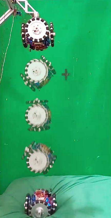
3.2   Modélisation cinématique et dynamique . . . . . . . . . . . . . . . . . . . .                                  34
   3.3   Forces d’impact et efforts internes . . . . . . . . . . . . . . . . . . . . . . . .                            41
   3.4   Conclusion . . . . . . . . . . . . . . . . . . . . . . . . . . . . . . . . . . . .                             43

4 Estimation de l’orientation d’une plateforme en apesanteur par filtre
  de Kalman étendu                                                                                                      45
  4.1 Préambule . . . . . . . . . . . . . . . . . . . . . . . . . . . . . . . . . . . . .                               45
  4.2 Introduction . . . . . . . . . . . . . . . . . . . . . . . . . . . . . . . . . . . .                              45
  4.3 Problématique . . . . . . . . . . . . . . . . . . . . . . . . . . . . . . . . . .                                 46
  4.4 Formulations généralisées des filtres de Kalman linéaire et étendu . . . . . .                                    47
  4.5 Approche proposée . . . . . . . . . . . . . . . . . . . . . . . . . . . . . . . .                                 49
  4.6 Protocole d’expérimentation . . . . . . . . . . . . . . . . . . . . . . . . . . .                                 52
  4.7 Résultats et Discussion . . . . . . . . . . . . . . . . . . . . . . . . . . . . . .                               54
  4.8 Conclusion . . . . . . . . . . . . . . . . . . . . . . . . . . . . . . . . . . . .                                60

Conclusion                                                                                                              61

A Conception du système de poulies                                                                                      64
  A.1 Introduction . . . . . . . . . . . . . . . . . . . . . . .    .   .   .   .   .   .   .   .   .   .   .   .   .   64
  A.2 Étape 1 : couple maximal . . . . . . . . . . . . . . .        .   .   .   .   .   .   .   .   .   .   .   .   .   64
  A.3 Étapes 2 et 3 : espacement des dents de la courroie .         .   .   .   .   .   .   .   .   .   .   .   .   .   65
  A.4 Étape 4 : ratio de réduction . . . . . . . . . . . . . .      .   .   .   .   .   .   .   .   .   .   .   .   .   65
  A.5 Étape 5 : vitesse de la courroie . . . . . . . . . . . .      .   .   .   .   .   .   .   .   .   .   .   .   .   65
  A.6 Étape 6 : longueur de la courroie . . . . . . . . . . .       .   .   .   .   .   .   .   .   .   .   .   .   .   66
  A.7 Étape 7 : largeur de la courroie . . . . . . . . . . . .      .   .   .   .   .   .   .   .   .   .   .   .   .   66
  A.8 Étape 8 : contact entre la courroie et la petite poulie       .   .   .   .   .   .   .   .   .   .   .   .   .   66
  A.9 Graphiques pour le choix de courroie . . . . . . . . .        .   .   .   .   .   .   .   .   .   .   .   .   .   66

Bibliographie                                                                                                           70

                                                 v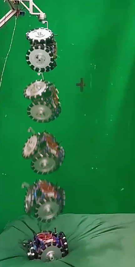
Liste des tableaux

1.1   Mass and inertia values of each link. Mass and inertia electronics to operate the
      motors are not included in these values. . . . . . . . . . . . . . . . . . . . . . .   14

2.1   List of Components with Mass and Inertia Values . . . . . . . . . . . . . . . . .      27

4.1   Erreur d’estimation moyenne sur l’ensemble de la trajectoire simulée en fonction
      des paramètres du critère contextuelle utilisée. . . . . . . . . . . . . . . . . . .   57

                                                vi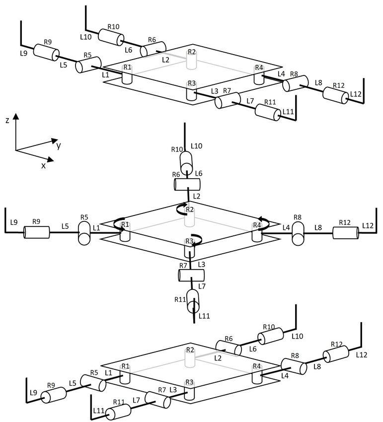
Liste des figures

1.1   General structure of a free-floating articulated robot with n links and n − 1
      actuated revolute joints, where ri defines a vector connecting the robot’s centre
      of mass (CM) to the centre of mass of each link, l0i and r0i are vectors connecting
      a link’s CM to the (i − 1)th and ith joints respectively and ei is a unit vector
      along the ith joint. Figure taken from [33]. . . . . . . . . . . . . . . . . . . . . .    6
1.2   Proposed robot architecture for free floating reorientation, composed of a cen-
      tral base and four appendages, each comprised of three links and three rotary
      joints. The upper image shows the robot’s first configuration, in which roll reo-
      rientation can be induced, and the lower image shows the robot’s second confi-
      guration, in which pitch reorientation can be induced. These configurations are
      referred to as the roll and pitch configurations respectively in this paper. The
      middle image demonstrates the transition from the roll configuration to the
      pitch configuration using joints R1 to R4, which are mechanically coupled. . . .         10
1.3   Reorientation manoeuvres for the roll configuration. The sequence of images of
      the left shows the progression of the coarse reorientation manoeuvre and the
      sequence of images on the right shows the progression of the fine reorientation
      manoeuvre. The sequence of motions that make up each manoeuvre remains
      the same for the pitch configuration. . . . . . . . . . . . . . . . . . . . . . . . .    11
1.4   Simulated robot architecture. Maxon EC-i 40 and RE-max 17 motors are used
      to simulate joints R5 to R8 and R9 to R12 respectively. The end piece structure
      is inspired from [37], with the cap on the end of each end piece serving as a
      means to adjust the weight and inertia of the end pieces. . . . . . . . . . . . . .      13
1.5   Simulated manoeuvres for the roll configuration. The upper sequence of images
      shows the progression of the coarse manoeuvre and the lower sequence of images
      shows the progression of the fine manoeuvre. A video demonstration of these
      manoeuvres is shown in https://youtu.be/XZs_ksSixFc. . . . . . . . . . . . .             13
1.6   Actuator torques for joints R5 to R12 throughout the coarse manoeuvre for an
      amplitude of rotation of the end pieces (R9 to R12) of 360 degrees while in the
      roll configuration. Similar results are obtained for the pitch configuration. . . .      15
1.7   Actuator torques for joints R5 to R12 throughout the fine manoeuvre with a
      folding angle (R5 to R8) of 90 degrees and an amplitude of rotation of the end
      pieces (R9 to R12) of 180 degrees while in the roll configuration. Similar results
      are obtained for the pitch configuration. . . . . . . . . . . . . . . . . . . . . . .    16
1.8   Base link linear and angular velocity throughout the coarse manoeuvre for an
      amplitude of rotation of the end pieces (R9 to R12) of 360 degrees while in the
      roll configuration. Similar results are obtained for the pitch configuration. . . .      17

                                                 vii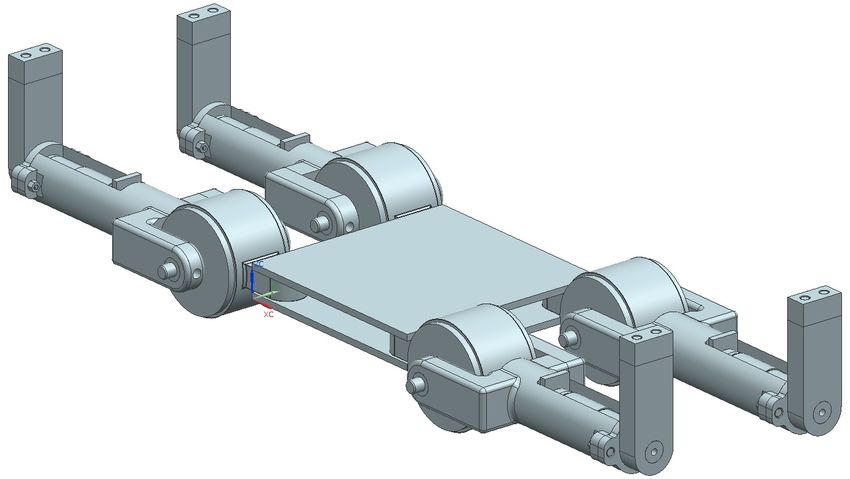
1.9 Base link linear and angular velocity throughout the fine manoeuvre with a
folding angle (R5 to R8) of 90 degrees and an amplitude of rotation of the end
pieces (R9 to R12) of 180 degrees while in the roll configuration. Similar results
are obtained for the pitch configuration. . . . . . . . . . . . . . . . . . . . . . . 17
1.10 Base link angle throughout the coarse manoeuvre with an amplitude of rotation
of the end pieces (R9 to R12) of 360 degrees while in the roll configuration (left)
and in the pitch configuration (right). . . . . . . . . . . . . . . . . . . . . . . . 18
1.11 Base link angle throughout the fine manoeuvre with a folding angle (R5 to R8)
of 90 degrees and an amplitude of rotation of the end pieces (R9 to R12) of 180
degrees while in the roll configuration (left) and in the pitch configuration (right). 18
2.1 CAD model of the proposed omnidirectional robot architecture in isometric
(left) and top (right) views. . . . . . . . . . . . . . . . . . . . . . . . . . . . . . 24
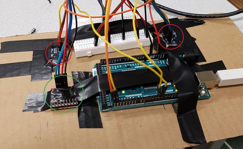
2.2 Top and bottom views of the prototype of the proposed architecture with the
main components identified. The electronics module is a stack of two prototy-
ping boards on which the Arduino Nano and step down module (upper layer)
and the inertial sensors (lower layer) are mounted. The inertial sensors are pla-
ced on a separate layer so as to place them as close as possible to the robot’s
centre of mass. . . . . . . . . . . . . . . . . . . . . . . . . . . . . . . . . . . . . 26
2.3 Still frames from the fast (left) and multi-axis (right) reorientation demonstra-
tions. These manoeuvres were filmed at 240 frames per second using a Samsung
A52 5G smart phone. A 10-cm thick foam mattress protects the falling proto-
type from impact forces on landing. . . . . . . . . . . . . . . . . . . . . . . . . 30
3.1 Les diagrammes de position, de vitesse et d’accélération angulaires des profils
de continuité de premier ordre étudiés. Les paramètres importants qui défi-
nissent chaque profil sont indiqués les axes appropriés. Les profils trapézoïdaux
considérés sont symétriques. . . . . . . . . . . . . . . . . . . . . . . . . . . . . . 36
3.2 Modèle CAD utilisé pour effectuer les simulations dynamiques dans Siemens NX. 39
3.3 Comparaison des exigences minimales en vitesse et en couple pour effectuer une
réorientation de 180 degrés en 0.45 secondes obtenues avec l’équation (3.16) et
de celles obtenues avec le modèle simulé à partir du CAD de la figure 3.2. . . . 39
3.4 Comparaison des exigences minimales pour effectuer une réorientation de 180
degrés en 0.45 secondes obtenues avec l’équation (3.16) et des spécifications de
courte durée du motor EC 45 80 watts pour différents ratios de réduction. Les
points rouges sur la courbe indiquent les performances de ce moteur pour des
ratios de réduction entiers. . . . . . . . . . . . . . . . . . . . . . . . . . . . . . . 40
3.5 Schématisation de l’arbre d’une roue ou d’un moteur. Les points A et B sont
les emplacements des deux roulements sur l’arbre. . . . . . . . . . . . . . . . . . 42
3.6 Diagrammes d’effort tranchant (gauche) et de moments de flexion (droite) pour
le cas illustré à la figure 3.5. . . . . . . . . . . . . . . . . . . . . . . . . . . . . . 43
4.1 Problème géométrique reliant le débalancement des mesures des LiDARs (L1 et
L2 ) et la séparation des LiDARS (b) à l’angle de la plateforme (θ). . . . . . . . 50
viii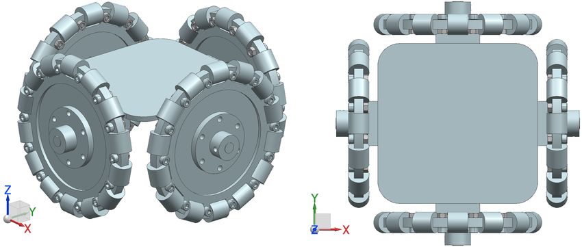
4.2   Cinq premiers graphiques : orientation et position de la plateforme (indiqué par
      le « x » noir) à certains points de la chute. La courbe en bleu représente la carte
      utilisée et les droites pointillées en rouge et vert sont les faisceaux des LiDARs.
      Dernier graphique : vitesse angulaire de la plateforme au cours de la chute par
      rapport à l’axe sortant du graphique. . . . . . . . . . . . . . . . . . . . . . . . .    53
4.3   Plateforme utilisée lors de la validation expérimentale. Les capteurs VL53L0X
      sont encerclés en rouge et la central inertielle LSM9DS1TR est encerclé en vert.         54
4.4   Reconstruction de la trajectoire effectué par la plateforme de la figure 4.3 à
      partir d’une vidéo haute vitesse (240 images par seconde). . . . . . . . . . . . .       55
4.5   Histogramme des données de calibration pour la mesure du premier capteur
      VL53L0X ainsi que le profil gaussien de moyenne et écart type correspondants
      (0.743 m et 0.00697 m respectivement). . . . . . . . . . . . . . . . . . . . . . .       55
4.6   Histogramme des données de calibration pour la mesure du deuxième capteur
      VL53L0X ainsi que le profil gaussien de moyenne et écart type correspondants
      (0.743 m et 0.00753 m respectivement). . . . . . . . . . . . . . . . . . . . . . .       56
4.7   Histogramme des données de calibration pour l’axe y du gyroscope (l’axe de
      rotation de la plateforme) ainsi que le profil gaussien de moyenne et écart type
      correspondants (0.0153 rad/s et 0.0113 rad/s respectivement). . . . . . . . . . .        56
4.8   Comparaison des différentes méthodes d’estimation de la pose de la plateforme
      dans le cas simulé optimal (A, B et p de −π/6, π/6 et 0.25 respectivement)
      où θtheo est l’orientation réelle de la plateforme, θw est l’estimation de l’inté-
      gration du gyroscope sur l’état précédent estimé par la méthode proposée, θL
      est l’estimation des mesures des LiDARs, θf est l’estimation du EKF, θest est
      l’estimation basé sur le critère contextuelle et θint est l’intégration pure des
      mesures du gyroscope. Les erreurs moyennes de chaque méthode d’estimation
      sont, respectivement, 0.220 rad, 1.203 rad, 0.551 rad, 0.0765 rad et 0.865 rad. .        58
4.9   Comparaison des différentes méthodes d’estimation de la pose de la plateforme
      dans le cas expérimental avec A, B et p de −π/6, π/6 et 0.25 respectivement
      où θpres est l’orientation de la plateforme obtenue de la vidéo haute vitesse, θw
      est l’estimation de l’intégration du gyroscope sur l’état précédent estimé par
      le méthode proposée, θL est l’estimation des mesures des capteurs ToF, θf est
      l’estimation du EKF, θest est l’estimation basé sur le critère contextuelle et
      θint est l’intégration pure des mesures du gyroscope. Les erreurs moyennes de
      chaque méthode d’estimation sont, respectivement, 0.106 rad, 0.363 rad, 0.162
      rad, 0.103 rad et 0.634 rad. . . . . . . . . . . . . . . . . . . . . . . . . . . . . .   59

A.1 Extrait des tableaux de vitesse de la section 21 de [81]. . . . . . . . . . . . . . .      65
A.2 Différents choix d’espacement de courroie selon la puissance d’opération et de
    la vitesse de la petit poulie. . . . . . . . . . . . . . . . . . . . . . . . . . . . . .   67
A.3 Graphique de vérification du couple maximal pour des courroie métriques. . . .             68
A.4 Graphique de vérification du couple maximal pour des courroie impériales. . . .            69

                                                 ix
Start where you are. Use what
you have. Do what you can.
Arthur Ashe
xRemerciements
Sans doute, je suis très fier de l’ampleur du travail que j’ai accompli dans les dernières années.
Toutefois, je ne peux pas prétendre avoir mené ce projet à terme seul et il n’aurait tout
simplement pas été possible de se rendre au but sans la contribution et le soutien de plusieurs
personnes. Je souhaite donc les remercier en soulignant l’impact qu’ils ont eu sur l’avancement
de mes travaux et, surtout, sur mon expérience aux études graduées en général.
Clément, dès mon premier stage au laboratoire en 2017, vous avez toujours pris le temps
d’assurer que je sois en position pour réussir, que ça soit par vos disponibilités flexibles, les
ressources que vous avez mis à ma disponibilité ou encore le sage conseil de vie occasionnel.
Malgré votre expérience et vos connaissances indéniables, vous avez toujours été ouvert à
mes idées et mes suggestions, me permettant d’ajouter ma touche personnalisée à tout projet
auquel j’ai eu la chance de participer (sans trop me laisser dévier du but ultime bien sûr !).
Alors que je dois maintenant aller de l’avant, sachez que vous m’avez aidé à bâtir un parcours
académique dont je suis extrêmement fier et je vous en serai toujours reconnaissant.
Simon et Thierry, malgré vos horaires très souvent surchargés, vous prenez toujours le temps
d’aider les étudiants avec leur projet et ce n’était pas différent dans mon cas. Que ce soit avec
vos conseils éclairés sur le choix de composants et le design de mon prototype, votre support
technique quotidien ou encore nos discussions enrichissantes, vous avez tous deux joué un rôle
essentiel à la réussite de cette maîtrise et, pour cela, je vous remercie énormément.
Aux membres du laboratoire, je tiens à vous remercier pour votre contribution à un environ-
nement de laboratoire propice à la discussion, l’apprentissage et surtout, les rires et le bon
temps. Sans doute le cas pour plusieurs parmi vous, la pandémie de la COVID-19 a eu son effet
sur l’ambiance au laboratoire et la motivation en général. Toutefois, récemment, j’ai senti que
l’ambiance que j’ai eu la chance de vivre au début de ma maîtrise commence à se rétablir et
cela est grâce aux efforts de plusieurs personnes qui prennent le temps d’organiser des activités
pour tous les membres du laboratoire. Je souhaite donc féliciter cette initiative et remercier
ceux qui y ont contribué. J’aimerais aussi faire une mention spéciale pour Vincent, avec qui
j’ai passé de nombreuses heures à discuter sur une grande variété de sujets (pas très souvent
pertinents, mais toujours divertissants) et j’ai pu partager une passion pour le tennis.
xiFinalement, je souhaite remercier ma famille pour leur support inconditionnel depuis le tout
début. À mes parents, les mots ne suffisent pas pour exprimer à quel point je suis reconnaissant
pour tous ce que vous avez fait pour moi. Aujourd’hui, je partage cette victoire, comme
les précédentes ainsi que celles à venir, avec vous, puisqu’après tout, sans vous, je ne me
serais jamais rendu où je suis. À mes frères, malgré vos forces et vos parcours distincts,
vous êtes tous les trois, à votre façon, une source d’inspiration quotidienne pour moi. Je
me considère extrêmement chanceux d’avoir non un, non deux, mais trois grands frères que
j’admire grandement.
xiiAvant-propos
Ce mémoire comprend deux articles rédigés au cours de la maîtrise. Le premier est un article de
journal publié et le deuxième est un article soumis. Ces articles sont inclus sans modifications
apportées au texte. Les références de ces articles sont données à la fin du mémoire avec les
références des autres chapitres. Une légère modification au titre de l’annexe du deuxième
article est effectuée pour que ce titre soit conforme avec le format de ce document. De plus, un
préambule est inclus dans le chapitre 2 afin de faire le lien entre les conclusions du chapitre 1
et les objectifs de ce deuxième chapitre. Les renseignements généraux concernant ces articles
sont fournis ci-dessous.
Le chapitre 1 de ce mémoire comprend un article publié dans le premier volume du Open Jour-
nal of Engineering de l’American Society of Mechanical Engineers (ASME) intitulé « Reorien-
tation of Free-Falling Legged Robots ». Je suis l’auteur principal de cet article ayant rédigé
le texte et complété les travaux qui y sont présentés. Le professeur Clément Gosselin, mon
directeur de recherche, est le seul coauteur de l’article. Il a supervisé les travaux présentés et
a contribué à la rédaction de l’article. Cet article a été soumis le 2 octobre 2021, accepté le 17
fevrier 2022 et publié le 4 mars 2022.
Le chapitre 2 de ce mémoire comprend un article de journal soumis à Robotics and Automation
Letters de l’Institute of Electrical and Electronics Engineers (IEEE) qui s’intitule « Multi-axis
Reorientation of a Free-falling Omnidirectionnal Wheeled Robot ». Je suis l’auteur principal
de cet article ayant rédigé le texte, mené la conception du prototype présenté et effectué
les démonstrations incluses dans l’article. Thierry Laliberté, un professionnel de recherche
au laboratoire de robotique de l’Université Laval, est un coauteur de cet article en raison
de ses contributions à la conception du prototype et des procédures pour les démonstrations
effectuées. Le professeur Clément Gosselin est aussi coauteur de l’article. Comme pour l’article
précédent, il a supervisé les travaux présentés et a contribué à la rédaction de l’article. Cet
article a été soumis le 31 janvier 2022.
xiiiIntroduction
Certains animaux, tels que les chats ou certains reptiles, peuvent se réorienter lors d’une
chute afin d’atterrir sur leurs pattes. Pour ce faire, ces animaux changent tout simplement
la disposition de leurs membrures lors de la chute et, suivant le principe de la conservation
de la quantité de mouvement angulaire, réussissent à se réorienter. L’intérêt de comprendre
ce phénomène, dont l’exemple le plus connu est celui du chat qui atterrit toujours sur ses
pattes, n’est pas récent. En effet, certains travaux tentent d’expliquer les manoeuvres de
réorientation animales d’un point de vue physiologique entre la fin du fin du 19e siècle et
le milieu du 20e siècle [1; 2; 3]. Suite à ces travaux, il a fallu attendre plusieurs décennies
avant l’apparition de modèles dynamiques plus complets dans la littérature. Kane et Scher
sont parmi les premiers à le faire en 1969. Avec leur modèle à deux cylindres, ils réussissent
à démontrer mathématiquement comment un chat peut effectuer une rotation de 180 degrés
lors d’une chute [4]. Inspirés par l’article de Kane et Scher, plusieurs autres études ont été
publiées dans les années qui suivent. Certains exemples importants comprennent l’étude des
manoeuvres de redressement d’animaux autres que les chats [5; 6] et l’étude des principes de
conservation de quantité de mouvement angulaire dans certains sports, tels que la gymnastique
et le plongeon [7; 8; 9; 10].
Naturellement, suite à cette vague de publications de divers modèles dynamiques décrivant
les manoeuvres de réorientation animales, l’intérêt de reproduire le mouvement a fait son
apparition dans le domaine de la robotique. Alors que la curiosité scientifique est certainement
un facteur motivant la recherche à ce sujet, les mouvements de réorientation ne sont pas sans
leurs applications. En effet, plusieurs méthodes de contrôle d’orientation de corps dans l’espace
se servent des principes des manoeuvres de réorientation et ce, autant pour développer des
stratégies de redressement pour les astronautes [11] que pour contrôler de robots spatiaux
[12; 13]. Les principes de réorientation s’avèrent aussi utiles pour le contrôle d’orientation de
robots terrestres, notamment dans le but de mitiger les dommages d’impact pour les robots
qui subissent régulièrement des chutes. Ce genre d’application se retrouve surtout chez les
robots sauteurs [14; 15] ou lors du déploiement de robots de secours dans des environnements
dangereux [16].
Au cours des années, de nombreuses techniques de réorientation pour les robots terrestres
1ont été publiées dans la littérature, mais dans la majorité des cas la réorientation effectuée
se limite selon un axe de rotation seulement. Un travail de maîtrise récemment complété au
Laboratoire de robotique de l’Université Laval s’est attaqué à ce problème en développant un
robot articulé inspiré des manoeuvres de redressement du chat pouvant se réorienter selon
ses axes de roulis et de lacet [17]. Puisque deux rotation distinctes suffisent pour effectuer
n’importe quelle rotation tridimensionnelle en un certain nombre de manoeuvres [18], il peut
être dit que le robot conçu au cours de ce travail est capable d’atteindre n’importe quelle
orientation possible. Cependant, surtout pour des courtes chutes, la capacité de se réorienter
selon l’axe de tangage au lieu de l’axe de lacet est beaucoup plus efficace lorsque l’objectif est
de se réaligner avec la surface d’atterrissage. Un article récent adresse ce point et présente un
robot mobile ayant les capacités de se réorienter selon ses axes de roulis et de tangage [19].
Toutefois, cela s’est fait au détriment de l’amplitude de réorientation puisque des amplitudes
de réorientation d’une vingtaine de degrés sont présentées dans cet article.
Le travail présenté dans ce mémoire vise à adresser les limitations de ces deux travaux en dé-
veloppant et en démontrant des manoeuvres de réorientation rapide et multiaxe. Un premier
objectif est donc de concevoir une nouvelle architecture articulée inspirée de [17] permettant
la réorientation selon ses axes de roulis et de tangage. La conception de cette nouvelle archi-
tecture et les simulations effectuées pour valider ses capacités de réorientation sont présentées
au chapitre 1. Le deuxième objectif de ce travail est de concevoir un robot mobile visant à
améliorer les performances de réorientation obtenues par le robot mobile développé dans [19].
Le chapitre 2 présente la conception et la validation expérimentale de l’architecture mobile
proposée et le chapitre 3 explicite certains détails supplémentaires concernant le développe-
ment du prototype. Finalement, en réponse aux limitations discutées au chapitre 2 concernant
la planification de manoeuvres de réorientation en temps réel, le chapitre 4 présente une tech-
nique de fusion de données par filtre de Kalman étendu qui permettrait d’estimer l’orientation
du prototype mobile développé en temps réel.
2Chapitre 1
Reorientation of Free-Falling Legged
Robots
1.1 Résumé
Cet article présente deux manoeuvres de réorientation inspirées du mouvement de redresse-
ment d’un chat appliquées aux robots à pattes permettant le redressement selon les axes de
roulis et de tangage. Pour caractériser et planifier ces manoeuvres, deux modèles mathéma-
tiques équivalents décrivant la cinématique et la dynamique des corps articulés en apesanteur
sont étudiés et formulés. Une architecture quadrupède généralisée est ensuite proposée pour
démontrer les manoeuvres étudiés. Des simulations cinématique et dynamique sont effectuées
et les résultats obtenus valident les modèles mathématiques présentés et démontrent l’efficacité
des manoeuvres proposées.
1.2 Abstract
Based on the cat righting reflex, this paper presents two reorientation manoeuvres for legged
robots that can produce roll and pitch reorientation during free fall. In order to better describe
and plan these manoeuvres, two separate, but equivalent, theoretical frameworks that describe
the kinematic and dynamic behaviour of free-floating articulated architectures are explored
and developed. A nine-degree-of-freedom quadruped robot architecture is then presented and
used to demonstrate the proposed manoeuvres. Finally, kinematic and dynamic simulations
of this architecture are performed. The results validate the presented theoretical framework
and demonstrate that both roll and pitch reorientation are obtained through the application
of the presented manoeuvres.
31.3 Introduction
Certain animals such as cats or lizards are capable of reorienting their bodies during a fall
to ensure that they always land on their feet. Among the first to mathematically model
this motion were Kane and Scher with their two cylinder cat, which demonstrated how cats
were able to attain 180 degree rotations about the roll axis [4]. Other analyses of the mid-
air reorientation manoeuvres followed, including further work by Kane and Scher on human
reorientation [7], as well as papers studying the motion in other animals [5; 6; 20] and in certain
sports, such as trampoline or diving [8; 9]. Another approach explored the use of gauge theory
in modelling the free falling cat problem [21].
Along with theoretical interest in reorientation manoeuvres, interest in potential applications
of the motion is also present, examples of which include satellite control using internal motions
or reaction wheels [22; 23; 24] and effector control for robot arms in space [25; 26; 27], to
name a few. A review on space robotics control is presented in [28]. More recent research
on the topic focuses on the application of the cat-righting motion to terrestrial robots, the
interest being impact mitigation during falls. This interest led to two separate ideas being
developed, namely 1) reorientation using an added actuated appendage, inspired by reptilian
reorientation manoeuvres by means of a tail, and 2) reorientation using closed-loop torso
and leg movements 1 inspired by Kane and Scher’s self-righting cat model. As far as reptilian
based methods are concerned, Jusufi et al. were among the first to present a reorientation
technique by which the addition of an appendage could allow for pitch axis rotation, which they
demonstrated using a reptile inspired prototype [29]. This method was then improved upon
through testing on wheeled robots in a subsequent series of papers [6; 30; 31]. Further work on
applied reptilian self-righting motions includes the use of an actuated tail for landing position
control in jumping robots [32; 15]. Regarding closed-loop motion inspired by the self-righting
motion of cats, notable contributions include the application of closed-loop manoeuvres for
the orientation control of free-floating planar manipulators [33] as well as the series of papers
studying the impact of the amplitude scaling of the internal motions on the resulting motion
in terms of reorientation amplitude and energy and force efficiency [34; 35].
Although much successful research pertaining to applied reorientation manoeuvres has been
done since Kane and Scher first published their self-righting cat model, most of the related
work is limited to reorientation about a single axis. For the reptilian inspired reorientation
manoeuvres, this is somewhat of an intrinsic limitation since the use of a single revolute joint
at the base of the added appendage only allows for reorientation about either the pitch or the
yaw axes. Although the number of degrees of freedom (DoF) between the tail and the robot
could be increased, the resulting reorientation is likely to be limited without sacrificing some
of the method’s simplicity. An example of this is work done by Chang-Siu et al., in which
1. Closed-loop movements refer to trajectories in the joint space for which the final configuration is identical
to the initial configuration. Such trajectories are sometimes referred to as "cyclic trajectories".
4multi-axis reorientation of a reptilian style robot is achieved with a two DoF tail at the cost
of a more sophisticated control system which must consider workspace limitations and avoid
singularities [36].
However, in the case of the cat inspired manoeuvres, which are generally more elaborate and
complex than the tail based manoeuvres, there is no physical limitation as to why the re-
sulting reorientation should be limited to one axis of movement. Garant et al. address this
by developing a three DoF articulated robot capable of completing two separate, closed-loop
manoeuvres which allow for reorientation about the roll and the pitch axes during free fall
[37]. Given that any given rotation in three dimensional space can be described as a linear
combination of rotations about any two distinct axes [18; 38], Garant et al.’s robot is thus
capable of producing any desired reorientation provided that the fall lasts long enough. Ne-
vertheless, notably for shorter falls, reorientation capabilities along the robot’s roll and pitch
axes would allow for much more efficient manoeuvres when it comes to controlling the desired
landing configuration. Indeed, the direction in which the robot faces when landing is not as
important as having it land in a configuration in which its main body axis is parallel to the
plane of the landing surface (generally the horizontal plane) as well as right side up.
In this paper, a nine-DoF articulated architecture capable of reorientation about the roll
and the pitch axes is presented with the aim of addressing the above mentioned limitations
present in existing architectures. The structure of the paper is as follows : Section 1.4 briefly
presents the theoretical framework used to describe the motion of free-floating robots and plan
the proposed manoeuvres, Section 1.5 presents the proposed architecture and describes the
manoeuvres used for reorientation and Section 1.6 presents the simulated results that demons-
trate the reorientation capabilities of the proposed architecture and validate the theoretical
framework. Finally, concluding remarks are given in Section 1.7.
1.4 Kinematic and Dynamic Analysis of Free-Floating Robots
In this section, the forward kinematics and dynamics of a general free-floating articulated
structure, illustrated in figure 1.1, is solved with the aim of obtaining mathematical models
that can be used to plan and validate the manoeuvres presented in the following sections of
this paper. Since free-floating robots lack a fixed attachment, standard methods for solving
these problems cannot be directly applied due to a lack of constraints. Vafa and Dubowsky
address this problem by using the virtual manipulator approach [26]. In this approach, a fixed
reference frame is set at the robot’s centre of mass and is then linked up to the end effector
using a virtual articulated chain for which the forward kinematics problem can be solved
sequentially. Using this method, the end effector kinematics can be fully defined, from which
the kinematics of the remaining links in the chain can also be obtained.
In the context of reorientation manoeuvres, the goal is to control the robot’s orientation,
5Figure 1.1 – General structure of a free-floating articulated robot with n links and n − 1
actuated revolute joints, where ri defines a vector connecting the robot’s centre of mass (CM)
to the centre of mass of each link, l0i and r0i are vectors connecting a link’s CM to the (i−1)th
and ith joints respectively and ei is a unit vector along the ith joint. Figure taken from [33].
which can be described using the orientation of any of the links in the chain, in this case,
the first link in the chain, referred to as the base link. Similarly to Vafa and Dubowsky’s
virtual manipulator approach, a fixed reference frame is set at the robot’s centre of mass and
is linked to the base link by means of a virtual, six-DoF joint. Three of these DoFs describe
the orientation of the base link with respect to the fixed reference frame and the other three
describe the components of the position vector of the base link’s centre of mass with respect
to the fixed reference frame. Once these six parameters are known, the forward kinematics
and dynamics problems can be applied to free-floating manipulators. In order to define these
six DoFs, additional constraints must be considered. Sections 1.4.1 and 1.4.2 show how force
and momentum conservation principles can be used to define the required constraints.
1.4.1 Augmented Dynamic Model
As previously mentioned, the general formulation of the dynamics of serial robots cannot be
solved for free-floating robots without the addition of further constraints. Such constraints
are defined by considering the virtual actuator parameters, in this case, the base link position
and orientation, as well as, the external forces applied to the robot’s base link. With these
additional constraints, an augmented formulation of the dynamics of serial mechanisms based
on the Lagrangian representation of the equations of motion, as described in [39], can be
written as :
" #
τ ∂T
= Maug ϕ̇aug + Ṁaug ϕaug − (1.1)
τ ext ∂θ aug
where τ is the vector containing the actuator torques, τ ext is the six-dimensional vector of
external forces, Maug is the robot’s generalized inertia matrix derived considering the augmen-
6ted articular parameters, T is the total kinetic energy of the manipulator and the augmented
articular position, velocity and acceleration vectors are defined as :
θ θ̇ θ̈
θ aug = rb , ϕaug = ṙb , ϕ̇aug = r̈b (1.2)
θb ωb ω̇ b
where θ, θ̇ and θ̈ are the articular position, velocity and acceleration vectors, rb , ṙb and r̈b
are the base link’s position, velocity and acceleration vectors and θ b , ω b and ω̇ b are the base
link’s orientation, angular velocity and angular acceleration vectors (all with respect to the
fixed reference frame). It is worth noting that equation (1.1) does not depend on the robot’s
potential energy because it does not affect the robot’s internal dynamics in the case of free-
floating and free-falling robots.
Equation (1.1) can be solved numerically by posing initial conditions for ṙb , θ b and ω b and
by determining rb from the robot’s centre of mass. External forces must also be known or
modelled. For free-falling applications, friction forces are generally the main external forces to
consider, but are often negligible for short falls. In such cases, τ ext from equation (1.1) can
be replaced with the zero vector of appropriate dimension. The initial values of Maug , Ṁaug
and ∂T
∂θ aug can then be obtained, leaving only r̈b , ω̇ b and τ as unknowns in equation (1.1).
Moreover, by defining
∂T
C≡ − Ṁaug ϕaug (1.3)
∂θ aug
and " # " #
M11 M12 C1
Maug = , C= , (1.4)
M21 M22 C2
equation (1.1) can be split into two separate sets of equations :
" #
r̈b
τ = M11 θ̈ + M12 + C1 (1.5)
ω̇ b
" #
r̈b
06×1 = M21 θ̈ + M22 + C2 (1.6)
ω̇ b
where Mij and Ci are submatrices of Maug and C respectively. Since it no longer depends
on τ , equation (1.6) can be solved for r̈b and ω̇ b , which are then inserted in equation (1.5)
to obtain τ . r̈b and ω̇ b are then integrated in order to obtain ṙb and ω b , which are used
to determine the base link’s orientation for the following time step, and rb is obtained from
the updated position of the robot’s centre of mass. The values of Maug , Ṁaug and ∂T
∂θ aug for
this time step can then be determined, after which equation (1.6) can be solved and so on. By
7repeating this process for each point in the prescribed trajectory, it is possible to fully describe
the kinematics and dynamics of a free floating robot.
1.4.2 Model Based on the Conservation of Momentum
Another approach that can be used to describe the kinematic and dynamic behaviour of free-
floating robots is similar to the one presented in [37]. In this approach, the forward kinematic
and dynamic problems are dealt with separately. Indeed, the laws of conservation of linear
and angular momentum are first used to complete the missing constraints in the kinematics
problem and the obtained solution is then used to round out the dynamics problem.
The general formulation of the law of conservation of linear and angular momentum for a
free-floating robot can be written as :
k
X
mj ṙj = pj0 (1.7)
j=1
k
X
(rj × mj ṙj + Ij ω j ) = lj0 (1.8)
j=1
where j indicates the link, mj its mass, rj its position vector with respect to the robot’s centre
of mass, ṙj its velocity vector, Ij its inertia matrix, ω j its angular velocity vector, pj0 its initial
linear momentum and lj0 its initial angular momentum. By assuming a stationary centre of
mass as well as by using the physical constraints that connect each link in the chain, it is
possible to express all the kinematic parameters of each link as a function of the kinematic
parameters of the link that precedes it in the chain, namely
rj = f (rj−1 , θ j−1 ) (1.9)
ṙj = f (ṙj−1 , ω j ) (1.10)
ω j = f ω j−1 , θ̇ j−1 . (1.11)
By applying equations (1.9), (1.10) and (1.11) to each of the robot’s links and then substitu-
ting them into equations (1.7) and (1.8), it is possible to rewrite these equations such that the
base link kinematic parameters are the only remaining unknowns. Furthermore, since these
equations are comprised of linear operations, all the terms relating to the base link can be
collected and all the terms relating to the articular parameters can be assembled separately.
Then, by combining the reformulated versions of equations (1.7) and (1.8), a general equa-
tion linking the base link parameters to the articular parameters can be obtained, with the
remaining quantities, such as the mass and inertia of each link, appearing in matrices A and
8B of dimension 6 × 6 and 6 × k respectively. It is worth noting that to obtain equation (1.12),
skew-symmetric matrices are used to represent the cross products that are present in equation
(1.8) in order to facilitate term factorisation [40]. One then obtains :
" #
ṙb
A = Bθ̇. (1.12)
ωb
The forward kinematics of free-floating robots can now be solved by obtaining ṙb and ω b from
equation (1.12), after which the dynamics can be solved using the top half of the augmented
dynamic model (equation (1.5)).
1.4.3 Comparison
Although both approaches successfully describe the kinematics and dynamics of a free floating
robot in the given conditions, it is important to note their differences in order to determine
when one is to be favoured over the other, both when describing the dynamics of any free-
floating articulated architecture and planning articular trajectories for any desire manoeuvre.
The main points on which these approaches differ are in terms of complexity and versatility.
Indeed, the model based on momentum conservation provides a more straightforward approach
in which the kinematics and dynamics can be solved separately and analytically, while the
augmented dynamic model requires a numerical approach to solve the kinematics and dynamics
of the robot. However, the augmented dynamics model provides a greater level of flexibility
since the torque constraints added to the augmented dynamic model can be used to represent
external forces, such as drag forces, acting upon the free-floating robot. This is not possible in
the momentum conservation based approach since momentum is only conserved in the absence
of external forces. It is worth noting that both methods can describe motions with non-zero
initial linear and angular momentum, assuming that these initial conditions are known.
1.5 Proposed Architecture and Reorientation Manoeuvres
The proposed nine-DoF robot architecture, shown in figure 1.2, is composed of a square base
to which four two-DoF, RR appendages are attached. The architecture of these appendages
is inspired from the robot presented in [37], with, referring to the configuration shown at the
top of figure 2, the first DoF allowing a rotation of the appendage about the y axis (joints
R5 to R8) and the second DoF allowing rotations of the end piece about the x axis (joints
R9 to R12). The remaining DoF controls the four rotary joints (R1 to R4) connecting each
appendage to the base, which are coupled by a mechanism that is not represented in figure
1.2. These serve solely to switch between the configurations.
9Figure 1.2 – Proposed robot architecture for free floating reorientation, composed of a central
base and four appendages, each comprised of three links and three rotary joints. The upper
image shows the robot’s first configuration, in which roll reorientation can be induced, and
the lower image shows the robot’s second configuration, in which pitch reorientation can be
induced. These configurations are referred to as the roll and pitch configurations respectively
in this paper. The middle image demonstrates the transition from the roll configuration to the
pitch configuration using joints R1 to R4, which are mechanically coupled.
The reorientation capabilities of the proposed robot architecture can be divided into two
separate closed-loop trajectories, shown in figure 1.3. Closed-loop trajectories are preferred to
open-loop ones because they ensure that the initial and final configurations of the robot are
the same. Based on the conservation of angular momentum, the presented trajectories both
reorient the robot along the same axis but differ in the amplitude of reorientation.
For the first manoeuvre (coarse manoeuvre), the end pieces are rotated at the same time and
in the same direction for a full rotation, causing the robot to rotate about the same axis in
the opposite direction. This manoeuvre can be repeated as many times as required to reorient
the falling robot, but cannot provide reorientation of smaller amplitude than the minimum
determined by the ratio of inertia between the four end pieces and the remainder of the links.
10Figure 1.3 – Reorientation manoeuvres for the roll configuration. The sequence of images
of the left shows the progression of the coarse reorientation manoeuvre and the sequence of
images on the right shows the progression of the fine reorientation manoeuvre. The sequence
of motions that make up each manoeuvre remains the same for the pitch configuration.
The second manoeuvre (fine manoeuvre), inspired by [37], is more elaborate, but more flexible
than the first one. Indeed, it can be used to obtain rotations of a smaller amplitude than
the coarse manoeuvre. The first step in the fine manoeuvre is to fold up the appendages of
the robot. Doing so increases the inertia of the main body and appendages to a value much
larger than that of the end pieces about the end pieces’ axis of rotation, meaning that the
end pieces can be rotated with little induced rotation of the remaining links. The end pieces
are then wound up to a certain angle in the direction opposite to the one that induces the
desired rotation. After unfolding the appendages, the end pieces can be returned to their initial
position, inducing the desired rotation of the robot. For end piece rotations of less than 360
degrees, this induced rotation can be of smaller amplitude than the minimal rotation induced
11by the coarse trajectory, while still maintaining the closed loop nature of the manoeuvre due
to the increased body and appendage inertias within the intermediate configuration. It is also
worth noting that the folding angle of the appendages (controlled by R5 to R8) can also be a
parameter used to adapt the fine manoeuvre depending on the required rotation.
With these manoeuvres and the ability to change configurations, the proposed architecture is
capable of reorienting itself about the roll and pitch axes and, therefore, can control its landing
configuration. Furthermore, with enough time, any desired three dimensional rotation of the
free falling robot can be obtained by sequencing these manoeuvres and configuration changes.
The exact sequence of manoeuvres and configuration changes required for a given desired
reorientation can be determined with the theoretical frameworks presented in the previous
section.
It is important to mention that the proposed architecture is built as a simplified quadruped
robot. This is done in order to show how the above presented manoeuvres can be completed
by certain existing legged robot architectures with little to no modification. Indeed, the coarse
manoeuvre can be completed by robots whose appendages have at least two R joints allowing
yaw and roll rotation (R1 and R5 in figure 1.2). Examples of quadruped robots that meet these
requirements are the Tekken robot [41; 42; 43], made to walk on difficult and irregular terrain,
and the walking and crawling ALoF robot [44]. Furthermore, some highly complex robots, such
as certain humanoid robots, are also capable of such reorientation manoeuvres, an example
of which is the BHR5 robot [45]. However, it should be noted that some quadruped robots
such as Boston Dynamic’s BigDog [46] and the MIT Cheetah [47] do not have yaw control of
their appendages, meaning that they cannot achieve both pitch and roll reorientation without
additional R joints on their appendages or a restructuring of their appendage architecture.
1.6 Simulated Results and Discussion
In order to validate the theoretical models and the manoeuvres presented, the robot archi-
tecture shown in figure 1.2 is modelled in a Siemens NX motion simulation (figure 1.4), and
both of the reorientation trajectories are reproduced (figure 1.5). Mass and inertia values of
each link are given in table 1.1. For all presented simulations, it is assumed that the robot has
no initial momentum. In the context of this paper, this assumption is justified as initial linear
momentum is of no consequence for reorientation manoeuvres and initial angular momentum
only affects trajectory planning and does not affect the feasibility of the motions. However, in
a more practical context, non-zero initial angular momentum could be measured using certain
sensors, such as gyroscopes, and then factored in during the trajectory planning phase.
During the simulation, the required torques and resulting base link (square base in this case)
kinematics are monitored and compared to the corresponding theoretical values for specific
trajectory amplitudes. These results for the roll configuration are shown in figures 1.6 to 1.9.
12Figure 1.4 – Simulated robot architecture. Maxon EC-i 40 and RE-max 17 motors are used
to simulate joints R5 to R8 and R9 to R12 respectively. The end piece structure is inspired
from [37], with the cap on the end of each end piece serving as a means to adjust the weight
and inertia of the end pieces.
Figure 1.5 – Simulated manoeuvres for the roll configuration. The upper sequence of images
shows the progression of the coarse manoeuvre and the lower sequence of images shows the
progression of the fine manoeuvre. A video demonstration of these manoeuvres is shown in
https://youtu.be/XZs_ksSixFc.
The simulation results are shown in green, while the augmented dynamics and momentum
conservation based models are shown in black and red respectively. Actuator torques for joints
R1 to R4 are not monitored as these joints are locked during the manoeuvres. As it can be
seen in these figures, the dynamic and kinematic behaviour of the robot is accurately modelled
by both of the presented theoretical methods for the roll configuration (the different curves
can hardly be distinguished on the graphs). Nearly identical results are obtained for the pitch
configuration, from which the same conclusions can be drawn. These results are omitted to
avoid redundancy. Therefore, the simulation results validate the presented theoretical models.
In order to verify and characterize the reorientation obtained from the proposed manoeuvres,
the base link’s orientation is also monitored during the motion simulation and is shown in
figures 1.10 and 1.11. From these figures, it is possible to note that rotation of the base link
is induced about the desired axis in all cases, validating the reorientation capabilities of the
proposed manoeuvres. It is also important to note that, for the chosen trajectory parameters,
13Vous pouvez aussi lire