User's Manual EV Series - Sun Country Highway
←
→
Transcription du contenu de la page
Si votre navigateur ne rend pas la page correctement, lisez s'il vous plaît le contenu de la page ci-dessous

EV Series Manual                                      Page ! 1

                      !

                    BRINGING SUSTAINABILITY TO LIFE

                   User’s Manual
                          EV Series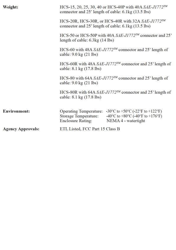
EV Series Manual                                                                   Page ! 2
 PLEASE NOTE
 This user’s manual includes the latest information at the time of printing. Sun Country
 Highway Ltd. reserves the right to make changes to this product without further notice.
 Changes or modifications to this product by other than an authorized service facility
 may void the product warranty.

 If you have questions about the use of this product, contact your customer ser- vice
 representative. Refer to the Customer Support section located in this guide.

EV Series Manual                                                                   Page ! 3

 EV User’s Manual, Version 6, June 2016 EV User Manual 06082016.indd Copyright© 2016. Sun
 Country Highway Ltd. All rights reserved. Printed in the USA.
EV Series Manual                            Page ! 4

                       CONTENTS
 IMPORTANT SAFETY INSTRUCTIONS          5

 ADDITIONAL SAFETY INFORMATION          7

 FCC INFORMATION                        8

 OPERATION                              8

 THE EV FRONT PANEL                     9

 INSTALLATION                          10

 SERVICE CONNECTIONS                   10

 MOUNTING PROCEDURES                   14

 MOUNTING THE CONNECTOR HOLSTER        17

 WIRING INSTRUCTIONS (Hardwired EV)    19

 RECEPTACLE INSTRUCTIONS               19

 CHARGE CABLE WRAP GUIDELINES          21

 GROUNDING INSTRUCTIONS                20

 MOVING & STORAGE INSTRUCTIONS         22

 CHARGEGUARD ENABLED EV INSTRUCTIONS   23

 MAINTENANCE                           25

 SHARE2TM ENABLED HCS INSTRUCTIONS     26

 CUSTOMER SUPPORT                      30

 SPECIFICATIONS                        31

 WARRANTY INFORMATION                  32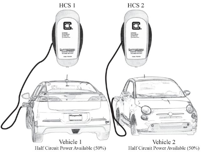
EV Series Manual                                                                      Page ! 5

IMPORTANT SAFETY INSTRUCTIONS
 Carefully read these instructions and the charging instructions in your vehicle owner’s
 handbook before charging your electric vehicle.
 The following symbols may be found in this manual or on labels affixed to the
 charge station:
           This means pay particular attention. Notes contain helpful suggestions.
           Cela signifie accorder une attention particulière. Les remarques
           contiennent des suggestions utiles.
           CAUTION: This symbol means be careful. You are capable of doing
           something that might result in damage to equipment.
           ATTENTION: Ce symbole signifie être prudent. Vous êtes capable de faire
           quelque chose qui pourrait causer des dommages à l’équipement.
           WARNING: This symbol means danger. You are in a situation
           that could cause bodily injury. Before you work on any electrical equipment,
           be aware of the hazards involved with electrical circuitry and standard
           practices for preventing accidents.
           AVERTISSEMENT: Ce symbole signifie un danger. Vous êtes dans une
           situation qui pourrait causer des blessures corporelles. Avant de travailler sur
           un équipement électrique, être conscient des dangers présentés par les circuits
           électriques et les pratiques courantes de prévention des accidents.

 Instructions Pertaining to a Risk of Fire or Electric Shock
 When using the the EV, basic electrical safety precautions should be followed:
                                                                                          tm
    •    Use this charge station to charge electric vehicles equipped with an SAEJ1772
         charge port only. Consult the vehicle owner’s manual to determine if the vehicle
         is equipped with the correct charge port.
                                                     tm
    •    Make certain the charge station SAE-J1772 charge cable is positioned so it will
         not be stepped on, tripped over, or otherwise subjected to damage or stress.
    •    This product contains no user serviceable parts. Consult the Customer Support
         section in this manual for service information. Do not attempt to repair or service
         the charge station yourself.
                                                                   tm
    •    Do not operate your charge station if it or the SAE-J1772 charge cable is
         physically open, cracked, frayed, or otherwise visibly damaged. Contact your
         Service Representative for service immediately. Consult the Customer Support
         section in this manual for information on the Service Representative in your
         area.
    •    Not for use in commercial garages where a COMMERCIAL GARAGE is
         defined as a facility (or portion thereof) used for the repair of internal
         combustion vehicles in which the area may be classified due to flammable
         vapors being present (such as from gasoline.)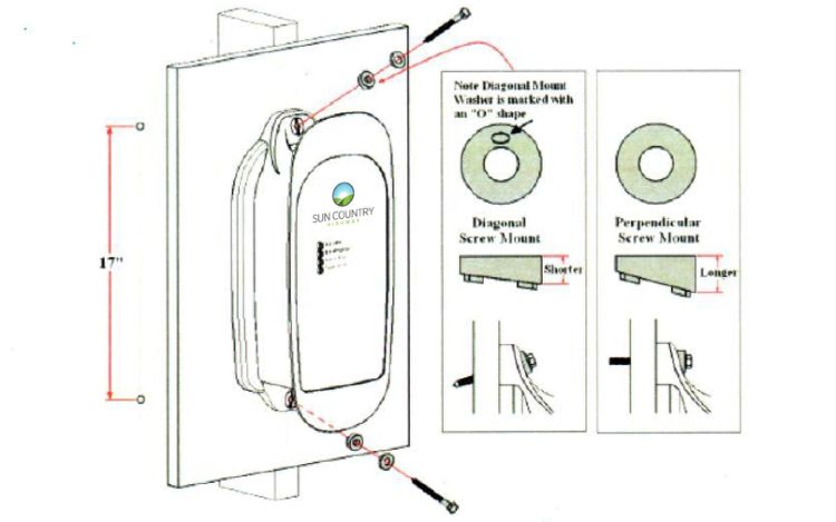
EV Series Manual                                                                      Page ! 6
                                                                          tm
    •    Do not place fingers inside of the coupler end of the SAE-J1772 charge cable.
    •    Do not allow children to operate this device. Adult supervision is mandatory
         when children are in proximity to a charge station that is in use.

 Instructions se Rapportant à un Risque d’Incendie ou de Choc Électrique

 Lorsque l’utilisation de la EV, précautions fondamentale de sécurité électrique
 doivent être suivies:

    •    Utilisez cette station de recharge pour charger les véhicules électriques équipés
                           tm
         d’un SAE-J1772 port de recharge seulement. Consultez le manuel du
         propriétaire du véhicule afin de déterminer si le véhicule est équipé d’un correcte
         port de recharge.
                                         tm
    •    Assurez-vous que le SAE-J1772 câble de recharge sur la station de re- charge
         est positionné de telle sorte qu’il ne sera pas piétiné, accroché plus de, ou
         autrement endommagé ou de subir le stress.
    •    Ce produit ne contient aucune pièce réparable par l’utilisateur. Consultez la
         section Support à la Clientèle dans ce manuel pour obtenir des informations de
         service. N’essayez pas de réparer ou d’entretenir la station de recharge vous-
         même.
    •    Ne faites pas fonctionner votre station ou le câble de recharge si elles sont
         physiquement ouverte, fissuré, effiloché, ou autrement visiblement endom-
         magé. Contactez votre représentant du service pour service immédiatement.
         Consultez la section Support à la clientèle dans ce manuel pour obtenir des
         informations sur le représentant du service dans votre région.
    •    Ne pas utiliser dans les garages commerciaux où un garage commercial est défini
         comme une installation (ou une partie) utilisé pour la réparation de véhicules à
         combustion interne dans lequel la zone peut être classée en raison de vapeurs
         inflammables étant présents (Tels que de l’essence.)
                                                                               tm
    •    Ne posez pas les doigts à l’intérieur de l’extrémité du SAE-J1772 coupleur du
         câble de recharge.
    •    Ne pas laisser les enfants utiliser cet appareil. Supervision d’un adulte est
         obligatoire lorsque des enfants sont à proximité d’une station de recharge qui est
         en cours d’utilisation.
    •
    •
EV Series Manual                                                                     Page ! 7

  ADDITIONAL SAFETY INFORMATION
            WARNING: Turn off input power to your charge station at the circuit breaker
            panel before servicing or cleaning the unit.
            AVERTISSEMENT: Couper l’alimentation d’entrée à votre station de
            recharge sur le panneau de disjoncteur avant de nettoyer ou de réparer
            l’appareil.

 NOTE
           VENTILATION: Some electric vehicles require an external ventilation system
           to prevent the accumulation of hazardous or explosive gases when charging
           indoors. Consult the vehicle owner’s manual to determine if your vehicle
           requires ventilation during indoor charging.
           VENTILATION: Certains véhicules électriques nécessitent un système de
           ventilation externe pour éviter l’accumulation de gaz explosifs
           ou dangereux lors de la charge à l’intérieur. Consultez le manuel du
           propriétaire du véhicule pour déterminer si votre véhicule nécessite une
           ventilation quand le recharge en salle.

 NOTE
                                                   tm
         Vehicles which conform to the SAE-J1772 standard for communication can
         inform the charge station that they require an exhaust fan. The EV is not
         equipped to control ventilation fans. Do not charge the vehicle with the EV if
         ventilation is required.
                                                              tm
         Véhicules qui sont conformes à la norme SAE-J1772 de communication
         peuvent informer la station de recharge qu’ils nécessitent un ventilateur
         d’extraction. Le EV n’est pas équipé pour contrôler les ventilateurs. Ne chargez
         pas le véhicule avec les EV si la ventilation est nécessaire.

         CAUTION: DO NOT CHARGE a vehicle indoors if it requires ventilation.
         Contact your Service Representative for information.
         ATTENTION: NE PAS RECHARGER un véhicule à l’intérieur si il nécessite
         une ventilation. Contactez votre représentant de service pour plus
         d’informations.

         Save these instructions for future reference. Conservez ces

         instructions pour référence future.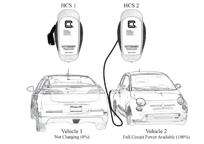
EV Series Manual Page ! 8
FCC INFORMATION
This device complies with Part 15 of the FCC rules. Operation is subject to the
following two conditions: (1) This device may not cause harmful interference, and (2)
This device must accept any interference received, including interference that may
cause undesired operation.
This product has been designed to protect against Radio Frequency Interference (RFI).
However there are some instances where high powered radio signals or nearby RF-
producing equipment (such as digital phones, RF communications equipment, etc.)
could affect operation.
If interference to your charge station is suspected, we suggest the following steps be
taken before consulting your Sun Country Highway Sales and Service Representative
for assistance:
1. Reorient or relocate nearby electrical appliances or equipment during
charging.
2. Turn off nearby electrical appliances or equipment during charging.
CAUTION: Changes or modifications to this product by other than an
authorized service facility may void FCC compliance.
ATTENTION: Modifications apportées à ce produit par qui conque autre qu’un
centre de service autorisé peut annuler la conformité FCC.
OPERATION
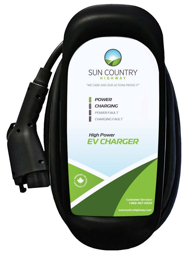
The EV Electric Vehicle Charging Station is a compact wall or pedestal-mount- ed
charging station that provides the Plug-in Hybrid or Battery Electric Vehicle (together
Plug-In Electric Vehicles, or “PEV”) user with a safe and manageable link between the
power grid and the PEV. Both hardwired (EV) and NEMA plug-equipped (EV-40P)
versions are available.
tm
The EV is very easy to use. Just unwrap the SAE-J1772 charge cable and plug the
charge coupler firmly into the vehicle’s charge port.
Normally, the vehicle will immediately request a charge using a special commu-
nication line in the cable. Within a few seconds the green “Charging” light on the face
of the EV will turn on and the charging cycle will begin. After an aver- age driving day
the vehicle battery pack will require several hours to recharge completely. Charging
overnight is the most convenient way to maintain healthy batteries and ensure the
vehicle’s full range will be available for the next day.
When the vehicle has stopped charging the green “Charging” light on the EV will turn
off. To remove the charge coupler once a charge cycle has completed (or to interrupt a
charge in progress) press and hold down the latch release lever on the charge coupler
handle then unplug the charge coupler from the vehicle charge port.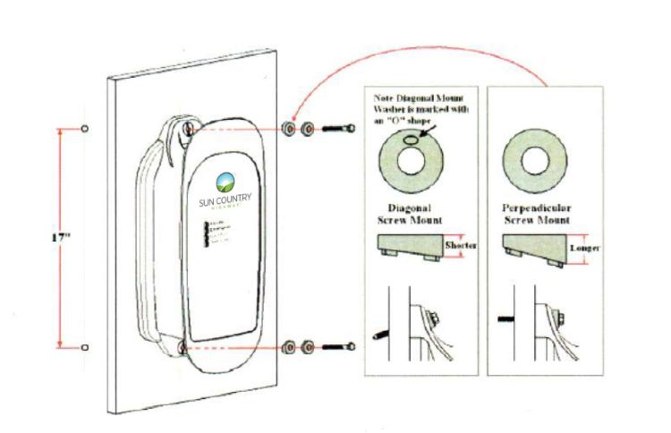
EV Series Manual                                                          Page ! 9

 THE EV FRONT PANEL
                                                  Figure 1. Front Panel
 The front panel on the EV has four indicator
 lights, as shown in Figure 1:

 POWER (yellow), indicates that power is
 available to the EV.

 CHARGING (green), indicates that the
 vehicle is requesting a charge and AC
 power is currently applied to the vehicle.

 POWER FAULT (red), indicates that
 the EV
 is not wired correctly. The problem can
 be due to improper grounding or a
 missing Earth Ground. The wiring
 should be examined by a qualified
 electrician.

 CHARGING FAULT (red), indicates that
 the EV is unable to communicate with the
 vehicle correctly, or a safety fault condition
 has been detected by the unit.

 Table 1. Front Panel LED Information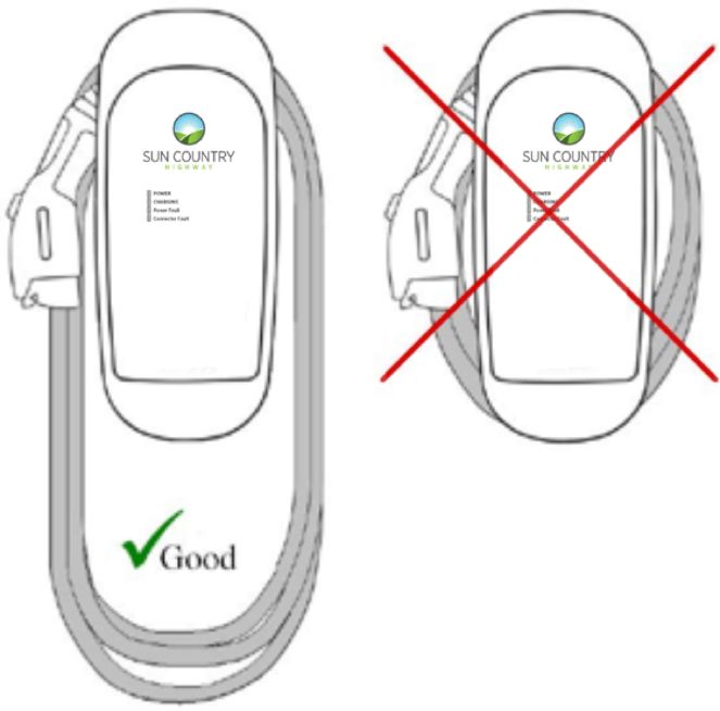
EV Series Manual                                                                      Page ! 10

 INSTALLATION
 SERVICE CONNECTIONS
          CAUTION: To reduce the risk of fire, connect only to a circuit provid- ed with
          the appropriate maximum branch circuit overcurrent protection in accordance
          with the National Electrical Code, ANSI/NFPA 70 (US) or the Canadian Electric
          Code C22.2 NO. 280-13 (Canada).

          ATTENTION: Pour réduire le risque d’incendie, de se connecter uniquement à
          un circuit fourni avec le approprié circuit de dérivation protection maximale
          contre les surintensités, en conformité avec le Code National électrique ANSI/
          NFPA 70 (US) ou Code Canadien de l’électric- ité C22.2 NO. 280-13 (Canada).

            EV Model                   EV Model                   EV Model

            EV Modèle                  EV Modèle                  EV Modèle

             EV-40 (Hardwired)                40A                   n/a

             EV-40P + NEMA 14-50P             50A                   NEMA 14-50R

             EV-60 (Hardwired)                60A                   n/a

          CAUTION: This is a single-phase device. Do not connect all three phases
          of a 3-phase feed !!! You may use any two phases of a three phase wye-
          transformer feed. The center-point of the three phases (usually used as Neutral)
          must be grounded somewhere in the system. A Neutral connection is not
          required by the EV. Only Line 1, Line 2, and Ground are required, as shown in
          Figure 3.

          ATTENTION: Il s’agit d’un appareil monophasé. Ne pas relier tous les
          trois phases d’une alimentation triphasée!!! Vous pouvez utiliser les deux
          phases d’un triphasé en étoile transformateur alimentation. Le point central des
          triphasé (généralement utilisé comme Neutre) doit être mis à la terre quelque
          part dans le système. Une connexion Neutre n’est pas exigée par la EV.
          Seulement ligne 1, ligne 2, et Mise à la Terre sont nécessaires, comme le montre
          la Figure 3.

          CAUTION: The two phases used must each measure 120V to Neutral. Earth
          Ground must be connected to Neutral at only one point, usually at the service
          entry breaker panel.

          ATTENTION: Les deux phases utilisées doivent mesurer chaque 120V à
          Neutre. Mise à la terre doit être connecté au Neutre en un seul point,
          généralement à l’entrée panneau de disjoncteurs de service.
          CAUTION: If a 240V 3-phase feed is from a Delta-connected second-
          ary,the leg used must have a center-tap. That tap must be Grounded. Only the
          two phases on either side of the center-tapped leg can be used. See Figure 4 on
          page 12.

          ATTENTION: Si une alimentation à triphasé 240V provient d’un trian- gle
          connecté secondaire, la bornes utilisée doit avoir un centre-tap. Que la tap doit
EV Series Manual Page ! 11
être Mise à la Terre. Seuls les deux phases l’une ou l’autre côté du centre tapped
brancher peut être utilisé. Voir la Figure 4 ci-des- sous.
CAUTION: Warranty is void if this unit is not wired properly
ATTENTION: La garantie est annulée si cette unité n’est pas cor-
rectement câblé
WARNING: Only a qualified electrician should perform the installation. The
installation must be performed in accordance with all local electri- cal codes
and ordinances.
AVERTISSEMENT: Seul un électricien qualifié doit effectuer l’instal- lation.
L’installation doit être effectuée conformément à tous les codes électriques
locaux et des ordonnances.
Only 3 wires are connected, but care must be taken that the service transformer
secondary connection is definitely known, and the 3 wires from the main circuit breaker
panel are connected and labeled correctly. Figures 2, 3, and 4 below show the most
common service transformer secondary wiring formats.
Notice that L1, L2, & Ground are labeled on each diagram. Those transform- er outputs
correspond to the same inputs on the EV. Also, each of the two
3-phase diagrams shows an L3 output, which is not used. Do not connect all
three phases of a 3-phase secondary to the EV. This is a single-phase device.
The Neutral at the service panel must be connected to Earth Ground somewhere in the
system on any of the three connection arrangements. Ground-fault pro- tection is not
possible unless the Neutral (center-tap on the service transformer) is connected to an
Earth Ground. If no Ground is provided by the electrical ser- vice, a grounding stake
must be driven into the Ground nearby, following local electrical codes. The grounding
stake must be connected to the ground bar in the main breaker panel, and Neutral
connected to Ground at that point.
WARNING: Local electrical codes must always be followed when
installing the grounding stake.
AVERTISSEMENT: Les codes électriques locaux doivent toujours être
respectées lors de l’installation du piquet de mise à la terre.
The following diagrams illustrate the three service transformer secondary
connections most common in North America.EV Series Manual Page ! 12
Figure 2 - 220/240V Single Phase
Figure 3 - 208V 3-Phase, Wye-Connected
NOTE
With a wye-connected secondary, any two of the legs can be used to provide
208V to the EV. For example, L1 & L2, or L1 & L3, or L2 & L3. Leave theEV Series Manual Page ! 13
unused leg open. Do not connect it to a Neutral bar, or to Ground. Be sure the
center point is grounded to Earth somewhere in the system.
Avec un transformateur étoile-connecté secondaire, deux des lignes peut être
utilisé pour fournir 208V à la EV. Par exemple , L1 & L2, ou L1 & L3, ou L2
& L3. Laissez la borne inutilisée ouverte. Ne le connectez pas à un bar Neutre,
ou à la Mise à la Terre. Assurez-vous que le point central est Mis à la Terre
quelque part dans le système.
Figure 4 - 240V 3-Phase, Delta-Connected, with center-tap on one leg
CAUTION: With the delta connection, one leg must be center-tapped. Only
the two phases on either side of the center tap can be used. The two phases
must both measure 120V to Neutral. The third line (L3)
of the delta is 208V, with respect to Neutral, and is sometimes referred to as a
“stinger”. Do not use this third line! Consult the transformer manufacturer’s
literature to be sure the single leg can supply the required power.
ATTENTION: Avec la connexion triangle, une borne doit être centre- tapped,
et seulement les deux phases d’un côté ou de l’autre du centre tap peut être
utilisé. Les deux phases doivent mesurer 120V à Neutre. Ta troisième ligne
(L3) du delta est 208V, par rapport à la position Neutre, et il est parfois désigné
comme un “stinger”. Ne pas utiliser ce troisième ligne! Consultez la
documentation du transformateur fabricant pour être sûr du borne unique peut
fournir la puissance requise.EV Series Manual Page ! 14
CAUTION: A 3-phase delta-connected transformer secondary without a
center-tap on one leg cannot be used with the EV. No “Neutral” point is
available to be connected to ground for ground-fault protection. The EV will
not allow the contactor to close if it does not sense the presence of a Ground
wire connected to a “Neutral” point on the transformer secondary.
ATTENTION: Un triphasé triangle-connecté transformateur secondaire sans
centre-tap sur le terminal ne peut pas être utilisé avec la EV. Aucun point
“Neutre” est disponible pour être connecté à Mise à la Terre pour protection de
défaut à la terre. Le EV ne
permettra pas le contacteur de fermer si elle ne détecte pas la présence d’un fil
de Masse connecté à un point “Neutre” sur le secondaire du transformateur.
MOUNTING PROCEDURES
Locate the wall mounting position of the EVSE:
¥ On the hardwired EV, the three service conductors are shielded by three feet of
flexible conduit. The EV must be positioned such that this conduit can reach a
nearby junction box.
¥ On the plug-in EV-40P, the NEMA plug head is connected by one foot of cable
(including the plug head) to the bottom side of the EV-40P. The
EV-40P must be positioned such that this plug can safely be inserted into a
wall-mounted NEMA socket.
¥ Position the bottom of the charge station at a comfortable height and at least 18
inches above the ground for indoor installations and 24” off the ground for outdoor
installations. Ensure that the LEDs on the front panel of the EVSE can clearly be
seen by anyone who will be operating the device.
¥ The EV has two vertically aligned mounting holes spaced 17” apart, one each on
the enclosure top and bottom. Use a ruler or template to mark hole locations on the
mounting surface.
WARNING: For safety, always turn off input power to the charge station at the
circuit breaker panel prior to plugging it in or wiring it to the service lines
Likewise, turn off the circuit breaker prior to unplugging it or disconnecting
the unit from the service lines.
AVERTISSEMENT: Pour sécurité, toujours désactiver le courant d’entrée de
la station de recharge au niveau du disjoncteur du panneau avant de le brancher
ou de câblage à les lignes de service. De même, coupez le disjoncteur avant de
le débrancher ou déconnecter l’unité à partir des lignes de services.EV Series Manual Page ! 15
FOR HOLLOW-WALL CONSTRUCTION
¥ Place the unit such that both mounting holes can take advantage of solid structural
framing inside of the wall or a strong wall surface such as ply- wood.
¥ Size ¼-20 lag screws are recommended for mounting the EV to a wooden structure.
Pre-drill appropriately sized pilot holes to allow the lag screw
to grip the wooden structure while preventing the wood from cracking or
splintering while the screw is fastened.
¥ The included plastic angle washers can be oriented to allow the lag screws to be
fastened at an angle while still providing a solid flat backing to the screw head.
¥ If the screw head is smaller than the 3/8” washer aperture, an additional flat washer
will need to be placed between the plastic angle washer and the head of the lag
screw.
¥ If either mounting hole does not have a solid mounting structure (such as drywall
without a solid backing) it will be necessary to use proper anchor- ing hardware
such as drywall toggles or molly bolts.
Figure 5. Mounting the EV to a hollow wallEV Series Manual Page ! 16
FOR SOLID-WALL CONSTRUCTION
¥ To secure the unit in concrete, pre-drill appropriately sized holes and use multi-set
or wedge anchor hardware at both mounting points.
¥ To secure the unit in brick or stone, pre-drill appropriately sized holes and use
sleeve anchors at both mounting points.
¥ The included plastic angle washers can be oriented to allow bolts to be fastened
either at an angle or perpendicular to the mounting surface. Note there are two
different sets of plastic angle washers included. Select those washers that best
accommodate the mounting hardware “angle of attack” and orient them accordingly.
¥ Note that if the head of the mounting hardware is smaller than the 3/8” plastic
angle washer aperture, an additional flat washer will need to be placed between the
plastic angle washer and the mounting hardware.
¥ Machine screw size ¼-20 hardware is recommended for mounting the EV.Screw
shafts of at least 2” are recommended. The EV plastic angle washer hole size is
3/8” in diameter, so ensure that the screw heads are of a larger diameter. Place
appropriately sized washers between the screw heads and the EV enclosure
mounting flanges.
Figure 6. Mounting the EV to a solid wallEV Series Manual Page ! 17
TM
MOUNTING THE SAE-J1772
CONNECTOR HOLSTER
tm
The SAE-J1772 connector holster is included to provide a convenient protec- tive
tm
housing for the the SAE-J1772 connector head when it is not in use.
tm
¥ The SAE-J1772 connector holster should be placed so that users have easy and
tm
safe access to the SAE-J1772 connector.
tm
¥ For indoor installation, mount the SAE-J1772 connector holster between 18 and 48
inches above the ground or grade.
tm
¥ For outdoor installation, mount the SAE-J1772 connector holster between 24 and
48 inches above the ground or grade.
tm
¥ The SAE-J1772 connector holster has two vertically aligned mounting holes
spaced 5.45” apart, one each on the enclosure top and bottom. Use a ruler or
template to mark hole locations on the mounting surface.
tm
¥ The vertical alignment of the EV and SAE-J1772 connector holster mounting
holes allows for the convenient mounting of both components onto the same post or
wall structure. For example, the holster may be mounted directly above the EV.
tm
¥ Place the SAE-J1772 connector holster such that both mounting holes can take
advantage of solid structural framing inside of the wall or a strong wall surface
such as plywood.
¥ A set of exterior wood screws and stainless steel washers are included for the
tm
purposes of mounting the SAE-J1772 connector holster to a wooden surface.
¥ For mounting to a solid surface such as concrete, brick, or stone, alternate hardware
may need to be procured. Examples of solid-wall mounting hard- ware include
muti-sets, wedge anchors and sleeve anchors. Use the type of mounting hardware
most appropriate for the supporting structure.
Figure 7. Mounting the holster using the exterior wood screws and washersEV Series Manual Page ! 18
WIRING INSTRUCTIONS
(Hardwired EV)
Route the EV conduit to a nearby junction box. Use the included ½” trade size
watertight conduit fitting and sealing washer to provide a moisture-resistant seal
between the conduit fitting and the junction box. If necessary, drill a 7/8”diame- ter
hole to accommodate the conduit fitting. For outdoor installations ensure the junction
box is fully sealed using appropriate electrical grade silicone sealant.
Before connecting the EV service conductors, please carefully read the section of this
manual titled Service Connections on page 9. If you are unsure of the type of power
provided at the service panel, please consult with your local utility or call your Service
Representative for assistance.
Figure 8. Wiring the EV in a junction box
The three supplied EV-20, 25, 30 or 40 EV-40 service
conductors use stranded 10 AWG 75ºC copper wire.
The three supplied EV-50, and EV-60 service con-
ductors use stranded 8 AWG, 75ºC copper wire.
The insulation of each conductor is color coded for
standard 240VAC installation:
Green: Ground
Black: Line 1 (120VAC to Ground) Red: Line 2
(120VAC to Ground)
Les trois EV-20, 25, 30 un EV-40 service conduc- teurs
fournis utilisent bloqués câble en cuivre 10 AWG 75ºC.
Les trois EV-50 fournis et conducteurs EV-60 uti-
lisent des services bloqués 8 fil de cuivre AWG, 75ºC.
L’isolation de chaque conducteur est un code couleur
pour l’installation de 240VAC norme:
Vert: Mise à la Terre
Noir: Ligne 1 (120VAC à Mise à la Terre) Rouge:
Ligne 2 (120VAC à Mise à la Terre)EV Series Manual Page ! 19
RECEPTACLE INSTRUCTIONS (Plug-In
EV-40P)
The EV-40P is fitted with either a NEMA 14-50P or 6-50P plug extending from the
bottom of the EV enclosure. Regulations limit this plug to a maximum of 12 inches in
length, including the plug head. For this reason, the EV-40P must be mounted above the
NEMA receptacle and must also be located within 12 inches of it.
In both NEMA 14-50P and 6-50P configurations, the ground pin is located at the
furthest point on the plug. With this in mind, it is recommended that a NEMA 14- 50R
or 6-50R receptacle be oriented accordingly, such that the ground sock- et is at the
lowest point.
Figure 9. Preferred orientation of the NEMA receptacles below the EV-40PEV Series Manual Page ! 20
CHARGE CABLE WRAP GUIDELINES
The EV enclosure body is sculpted to allow the charge cable to be wrapped around it for
convenient storage as well as to keep the bulk of the cable off of the ground and out of
the way. As the charge cable is comprised of a number of wires, coiling the charge cable
too tightly around the EV enclosure will result in the charge cable feeling warmer to the
touch than would ordinarily be the case.
To minimize this effect, it is recommended that the charge cable be loosely draped
around the EV enclosure body with larger loops. This will also permit greater
convenience in “pulling off” additional loops if a longer charge cable reach is desired.
Figure 10. Drape the charge cable loosely around the EV enclosureEV Series Manual Page ! 21
GROUNDING INSTRUCTIONS
This product must be grounded. If this product should malfunction or break down,
grounding provides a path of least resistance for electric current to reduce the risk of
electric shock.
For the hardwired EV:
The hardwired EV is equipped with three service conductors shielded by three feet of
flexible conduit. This product must be connected to a grounded, metal, permanent
wiring system, or an equipment-grounding conductor must be run with the circuit
conductors and connected to the ground lead on the product.
For the plug-in EV-40P:
The plug-in EV-40P is equipped with a cord having an equipment grounding conductor
and a grounding plug. The plug must be plugged into an appropriate outlet that is
properly installed and grounded in accordance with all local codes and ordinances.
WARNING: Improper connection of the equipment-grounding conductor may
result in a risk of electric shock. Check with a qualified electrician if doubt
exists as to whether the product is properly grounded. Do not modify the plug
provided with the product – if it will not fit the outlet, have a proper outlet
installed by a qualified electrician.
AVERTISSEMENT: Une mauvaise connexion du conducteur de terre peut
entraîner un risque de choc électrique. Vérifier avec un électricien qualifié si il
existe un doute quant à savoir si le produit est correctement mis à la terre. Ne
pas modifier la fiche fournie avec le produit – si elle n’entre pas dans la prise,
faites installer une prise adéquate par un électricien qualifié.
MOVING & STORAGE INSTRUCTIONS
Note that both the hardwired EV and the plug-in EV-40P are intended for fixed
installations. For mounting requirements, consult the Mounting Procedures section of
the Installation Instructions in this manual.
Always turn off input power to the charge station at the circuit breaker panel prior to
hard-wiring an EV to or disconnecting an EV from the service lines. Likewise, always
turn off input power to the charge station at the circuit breaker panel prior to plugging
an EV-40P into or unplugging an EV-40P from a NEMA socket.
When transporting the charge station, do not lift or carry the entire unit by the SAE-
tm
J1772 charge cord. Likewise, do not lift or carry the entire unit by the flexible conduit
and input conductors (EV) or the NEMA plug (EV-40P).
The charge station has a non-operational storage temperature range of -40°C to
+80°C (-40°F to +176°F).EV Series Manual Page ! 22
CHARGEGUARD ENABLED EV
INSTRUCTIONS
Please refer to these instructions to operate the
ChargeGuard enabled EV
EVSE:
1. Connect the HCS EVSE to the vehicle with the
SAE-J1772TM connector.
2. To enable charging:
a) Insert the key into the switch located on the right
side of the HCS EVSE. b) Turn the key 90°
clockwise to the vertical position as shown in the
ChargeGuardTM Addendum Figure 1.
c) The “CHARGING” LED light will illuminate
green on the front panel, indicating the vehicle is
now being charged.
3. To allow charging of Multiple Vehicles:
a) Leave the key in the present vertical position. This
allows disconnection of the EVSE from one vehicle
and reconnection
to the same or another vehicle without moving the
key.
b) The EVSE will be enabled and power will be
available to vehicles as long as the key remains in
the vertical position.
NOTE: The key cannot be removed in the vertical position. See step 4 for key removal
instructions.
4. To restrict access:
a) Turn the key counterclockwise 90° as shown in ChargeGuardTM Addendum Figure 2.
b) Remove the key.
c) If a vehicle is connected and charging, that vehicle will continue to charge as long it
remains connected to the EVSE.
d) Once the vehicle is disconnected from the EVSE, the EVSE will require the key to
activate another charging session.
REPLACEMENT KEYS
If you need replacement keys, please contact the Sun Country Highway office at (866)
467-6920. Please have the serial number of your EVSE available for reference.EV Series Manual Page ! 23
ChargeGuardTM EX HCS INSTRUCTIONS
ChargeGuardTM EX provides a simple interface to connect the ClipperCreek HCS
EVSE to an existing building access control or other third party access control system.
With ChargeGuardTM EX a momentary contact closure driven by successful
authentication in an access control system can activate the HCS ChargeGuardTM EX
enabled station for a single charging session. Alternatively, maintaining the contact
closure will leave the station enabled for multiple charging sessions until the
connection is released. When the orange and yellow control wires are shorted together,
the EVSE is “ON” and ready to charge a vehicle. When the wires are disconnected, the
station is “OFF” and requires a valid activation through the access control system in
order to begin charging again. ChargeGuardTM EX can be utilized in two ways:
1. If individual access control is desired (for each charge session), the access
control system will need to provide a momentary short to the orange and yellow
wires which will activate the station for a single charge session. In this
implementation once the vehicle is disconnected the station will require a
successful authorization through the access control system.
2. If open access is desired, connect the orange and yellow wires for as long as open
access is desired. As long as the orange and yellow wires are shorted together, the
station will be enabled for use.EV Series Manual Page ! 24
Figure 1. ChargeGuardTM EX
Yellow Wire Orange Wire
Figure 2. ChargeGuardTM EX: Wiring
Please refer to these instructions to operate the ChargeGuardTM EX enabled HCS
EVSE:
1. Connect the HCS EVSE to the vehicle with the SAE-J1772TM connector.
2. Enable charging by using access control.
3. The “CHARGING” LED light will illuminate green on the front panel, indicating
the vehicle is now being charged.EV Series Manual Page ! 25
MAINTENANCE
The EV requires no periodic maintenance other than occasional cleaning.
WARNING: To reduce the risk of electrical shock or equipment damage,
exercise caution while cleaning the unit and the EV charge connector cable.
1. Turn off the charge station at the circuit breaker before cleaning.
2. Clean the charge station using a soft cloth lightly moistened with mild
detergent solution. Never use any type of abrasive pad, scouring powder,
or flammable solvents such as alcohol or benzene.
AVERTISSEMENT: Pour réduire le risque de choc électrique ou des
dommages équipement, user de prudence lors du nettoyage de l’appareil et le
câble du connecteur de charge EV.
1. Eteignez la équipement au disjoncteur avant de le nettoyer.
2. Nettoyez l’équipement à l’aide d’un chiffon doux légèrement humidifié
avec une solution de détergent doux. Ne jamais utiliser de tampons
abrasifs, de poudre à récurer ou de solvants inflammables tels que l’alcool
ou le benzène.EV Series Manual Page ! 26
TM
Share2 Enabled HCS INSTRUCTIONS
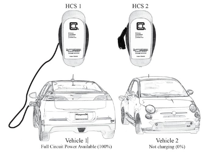
Share2TM allows two EVSE to share power supplied by one circuit breaker. When
only one EVSE is charging a vehicle, the full charging capacity is available to that
vehicle. When both EVSE are charging vehicles, each EVSE will offer 50% of the
circuit capacity to each vehicle (thus “sharing” the circuit breaker). Follow the
Share2TM Wiring Instructions in the following section.
Share2TM Wiring Instructions:
Follow the Wiring Diagram below for proper wiring of Share2TM. Wiring connections
can be made in a junction box or pedestal body (ClipperCreek pedestal bodies double
as electrical raceways). Strip the blue, brown and white wires ONLY. Use wire nuts
(not included) to secure the blue and brown wires to the opposing white wire as
indicated by the black dots in Share2TM Figure 1.
WARNING: DO NOT STRIP WIRES THAT ARE UNUSED.
Share2TM - Figure 1EV Series Manual Page ! 27
Verify Share2TM Function is working properly:
After wiring is complete use a DC volt meter to test functionality. Connect the volt
meter negative lead to ground, then connect the volt meter positive lead to the white
wire. A measurement greater than 4VDC should be seen when a vehicle is not
connected or not charging. A voltage less than 1VDC will be measured on the white
wire when a vehicle is charging.
NOTE: There is a 5 second delay once one vehicle stops charging before the white
wire returns to greater than 4VDC and an additional 10 seconds before full circuit
power will be available to the other vehicle.
Share2™ Operating Instructions:
1. Connect Vehicle #1 to either HCS #1 or HCS #2 with the corresponding SAE-
J1772™ connector. Vehicle #1 will have access to the full power available through
that circuit.
2. Connect Vehicle #2 to the remaining EVSE with the SAE-J1772™ connector. Each
vehicle will now have access to half of the power available through that circuit.
3. If one vehicle disconnects or completes charging, the other vehicle will have access
to the full circuit power after 15 seconds.
Share2TM Figure 2: Connect Vehicle #1EV Series Manual Page ! 28
Share2TM Figure 3: Connect Vehicle #2
TM
Share2 Figure 4: One of the vehicles disconnects or completes chargingEV Series Manual Page ! 29
OPTIONAL: Share2™ operation if Optional
TM
ChargeGuard is also installed:
If the ChargeGuard™ option is desired to work in conjunction with the Share2™
option, these two options must be ordered and built at the same time (Share2™ and
ChargeGuard™ are factory-installed options and cannot be installed in the field). The
TM
optional ChargeGuard feature allows charging to be enabled or disabled with the
use of a key. Please refer to the ChargeGuardTM section in this User Manual for further
instructions.EV Series Manual Page ! 30 CUSTOMER SUPPORT Call your Sun Country Highway Ltd. Service Representative for service and warranty assistance. PLEASE HAVE THE MODEL NUMBER AND SERIAL NUMBER AVAILABLE WHEN YOU CALL. This information is printed on the label on the side of the charger’s enclosure. If your call is made after business hours or on weekends, please leave your name, telephone number, the unit serial number, and a brief description of the problem. A Service Representative will call back at the earliest opportunity. To contact Sun Country Highway Ltd. Directly for service: call 1 866 467-6920 Ext. 3 Monday to Friday between 8:00 am and 5:00 pm central standard time. You can also email warranty@suncountryhighway.ca.
EV Series Manual   Page ! 31

 SPECIFICATIONS
EV Series Manual Page !32
EV Series Manual                                                                               Page !33

                   WARRANTY INFORMATION

            LIMITED WARRANTY – ELECTRIC VEHICLE SUPPLY EQUIPMENT
                              MODEL: EV SERIES
                             Sun Country Highway Ltd.
                      7208 Bow Cres. NW, Calgary AB, T3B 2B9
                                  1 866 467-6920

Sun Country Highway shall provide the following warranty with respect to the Products to
Representative, its Sub-Representatives and their customers:

Product 3-year parts, 3-year factory labor,

Sun Country Highway, Inc. warrants this product to be free from defects in material and
workmanship. The warrantee period shall commence on the date of installation date (first use). The
product installation date must be evidenced and communicated to Sun Country Highway by way of
the warrantee registration card (or its equivalent). The warrantee registration card must be filled out
completely and accurately, and returned to Sun Country Highway within 30 days after installation,
and the product installation date shall be within 6 months after the purchase date. If a Product
installation date is not communicated to Sun Country Highway as described above, the product
purchase date shall serve as the warranty commencement date.

If this product is defective in materials or workmanship during the warranty period, Sun Country
Highway will, at its option, repair or replace the product. Repair parts and /or replacement products
may be either new or reconditioned at Sun Country Highway’s discretion. This limited warranty
does not cover service or parts to repair damage due to improper installation or use, including but
not limited to improper connections with peripherals, external electrical faults, accident, disaster,
misuse, abuse or modifications to the product not approved in writing by Sun Country Highway.
Any service repair outside the scope of this limited warranty shall be at applicable rates and terms
then in effect. The warranty covers factory parts and labour only; it does not cover field service or
removal and replacement of the product or any other costs.

All other express and implied warranties for this product including the warranties of
merchantability and fitness for a particular purpose, are hereby disclaimed. Some states do not
allow the exclusion of implied warranties or limitations on how long an implied warranty lasts, so
the above limitation may not apply to you.

If this product is not as warranted above, your sole and exclusive remedy shall be repair or
replacement as provided above. In no event will Sun Country Highway, any of its authorized sales
and service representatives, or its parent

company be liable to customer or any third party for any damages in excess of the purchase price of
the product.

This limitation applies to damages of any kind including any direct or indirect damages, lost
profits, lost saving or other special, incidental, exemplary or consequential damages whether for
breach of contract, tort or otherwise or whether arising out of the use of or inability to use the
product, even if Sun Country Highway or an authorized Sun Country Highway representative or
EV Series Manual Page !34
dealer has been advised of the possibility of such damages or of any claim by any other party. Some
states do not allow the exclusion or limitation of incidental damages for some products, so the
above limitation or exclusion may not apply to you.
This warranty gives you specific legal rights, and you may also have other rights which may vary
from state to state.
To obtain warranty service:
Call your nearest authorized Service Representative or Sun Country Highway at the above number.
You will receive information as to how service for the product will be provided.
If you mail or ship the product in for service, you must insure the product, prepay all shipping
charges, and properly pack it for shipment in its original shipping container or its equivalent. You
are responsible for all loss or damage that may occur in transit.
You must provide proof of purchase of the product and the purchase date before any warranty
service can be performed. This limitation applies to damages of any kind including any direct or
indirect damages, lost profits, lost saving or other special, incidental, exemplary or consequential
damages whether for breach of contract, tort or otherwise or whether arising out of the use of or
inability to use the product, even if Sun Country Highway or an authorized Sun Country Highway
representative or dealer has been advised of the possibility of such damages or of any claim by any
other party. Some states do not allow the exclusion or limitation of incidental damages for some
products, so the above limitation or exclusion may not apply to you.
This warranty gives you specific legal rights, and you may also have other rights which may vary
from state to state.
Note: All Ruggedized 'R' Models have an extended warranty of 5-years: Product 5-year parts,
5-year factory labor
Sun Country Highway
7208 Bow Cres NW
Calgary AB, T3B 2B9
1-866-467-6920
info@suncountryhighway.caVous pouvez aussi lire