AURA (L) Light Engine Instruction Manual - Lumencor,Inc. DocumentNumber57-10012 www.lumencor.com
←
→
Transcription du contenu de la page
Si votre navigateur ne rend pas la page correctement, lisez s'il vous plaît le contenu de la page ci-dessous

AURA (L) Light Engine ®
                 Instruction Manual

Lumencor, Inc.       Document Number 57-10012   www.lumencor.com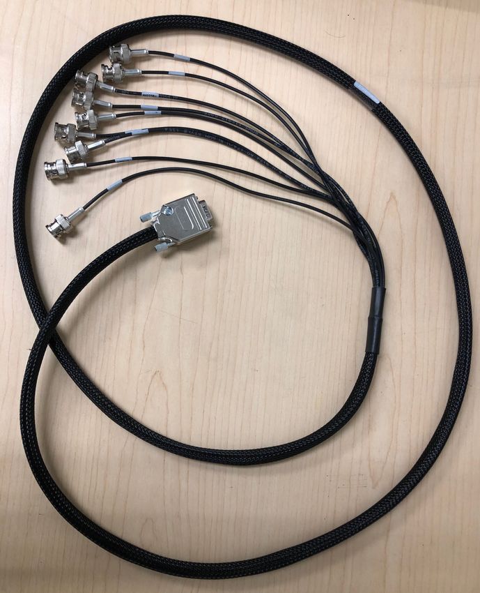
Regulatory Models
Lumencor utilizes regulatory model names for all certified and CE marked products. The regulatory model names are
traceable to all regulatory documentation, third party reports and certifications.

“Regulatory Model: Aura III L” is used as a representative model for all certified and CE marked AURA (L) Laser
products.

Emissions
This equipment has been tested and found to comply with the limits of EMC directive 2014/30/EU and FCC part 15
(CISPR 11:+A1:2016). These limits are designed to provide reasonable protection against harmful interference when the
equipment is operated in a commercial environment. This equipment generates, uses, and can radiate radio frequency
energy and, if not installed and used in accordance with the instruction manual, may cause harmful interference to radio
communications.

Safety Certifications
TUV SUD America, CB Certification (IEC 61010-1:2010)
TUV SUD America, NRTLus Certification (UL 61010-1:2012-05)
TUV SUD America, cNRTL Certification (CAN/CSA-C22.2 No. 61010-1:2012)
TUV SUD America, EN Certification (EN 61010-1:2010)
Underwriters Laboratories (UL), CB Certification (IEC/EN 60825-1:2014 Safety of laser products)

CE Marking
Low Voltage Directive (2014/35/EU)
EMC Directive (2014/30/EU)
RoHS Directive (2011/65/EU+2015/863/EU)
REACH Regulation (EC) No. (1907/2006/EC)

EU Declarations of Conformity can be found at http://lumencor.com/company/regulatory-compliance/

For EU customers discarding end-of-life Lumencor electrical and electronic equipment: Please submit an RMA request
with “Recycle product under WEEE” in the Description of Issues field.

For disposal in countries outside of the European Union: This symbol is only valid in the European Union (EU). If you wish
to discard this product, please contact your local authorities or dealer and ask for the correct method of disposal.

 Lumencor Light Engines as supplied, and as represented in this manual, meet safety and regulatory requirements For
 Research Use Only. If the light engine is incorporated into an instrument or system for a specific end-use application,
 it is the responsibility of the system integrator to verify that the light engine, and the system into which it is
 incorporated, meet all safety and regulatory requirements of that end-use application.

Lumencor, Inc. | 14940 NW Greenbrier Parkway | Beaverton, OR 97006 USA | 503.213.4269 | www.lumencor.com

Document Number 57-10012
Revision E
061421

AURA (L) Light Engine® Instruction Manual                                                                                  2
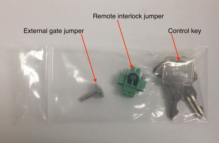
Table of Contents

1. Introduction

2. Precautions and Warnings

3. Installation and Operating Instructions

4. Light Output Characteristics

5. Operational Specifications

6. Routine Maintenance and Trouble Shooting

7. Customer Support

8. Warranty

AURA (L) Light Engine® Instruction Manual     3
1. Introduction
The AURA (L) Light Engine consists of 3 to 5 individually addressable solid-state light sources with integrated electronic
control systems. The constituent light sources may be LEDs, luminescent light pipes or lasers. Optimal internal
operating temperature is maintained by negative pressure air cooling with the air intake at the front of the light engine and
the exhaust fan at the the rear. The outputs of the constituent light sources are refined by bandpass filters and merged
into a common optical train directed to the light output port on the front panel. The light output port has a built-in
adapter for connection to an SMA-terminated optical fiber or a liquid light guide (LLG). An onboard photodiode
continuously monitors the light output and generates a reference signal that is applied to the constituent sources in a
feedback loop to maintain constant light output over time. The light sources within the AURA (L) Light Engine® are
controlled by software via one of two serial interfaces, USB/RS-232 or TCP, to the on board computer operating
Lumencor firmware. The user can enable or disable each source independently by serial commands as well as change
the intensity of each source independently. The AURA (L) Light Engine can either be controlled by a Lumencor GUI, by
third party microscopy data acquisition software or by a LAN connection to an onboard computer with an embedded
command library. Alternatively, the light sources may be turned on and off by TTL inputs from a trigger device such as a
camera. The only manual control is the master power switch on the front panel to turn on/off the electrical power into the
unit.

AURA (L) Light Engine® Instruction Manual                                                                                  4
2. Precautions and Warnings {Précautions et mises en garde}
A few simple practices will ensure trouble-free operation for the life of the light engine.

Les quelques règles simples suivantes permettront d’assurer un fonctionnement fiable pendant toute la durée de service
de la source lumineuse.

Safety Instructions:
Please read and follow all safety instructions provided BEFORE using the AURA (L) Light Engine®. Failure to comply with
the safety instructions may result in fire, electrical shock, or personal injury and may damage or impair protection
provided by equipment. Please save all safety instructions.

Instructions de sécurité:
Veiller à lire et à respecter toutes les instructions de sécurité fournies AVANT d’utiliser le AURA (L) Light Engine® afin
d’écarter les risques d’incendie, de décharge électrique, de blessure corporelle et de possibles dommages ou défaillance
de la protection offerte par l’appareil. Conserver toutes les instructions de sécurité.

Safety Definitions {Définitions relatives à la sécurité}:

                  Warning: Statements identify conditions or practices that could result in personal injury.

                  Avertissement: déclarations qui identifient des situations ou des pratiques susceptibles d’entraîner
                  des blessures corporelles.

Caution: Statements identify conditions or practices that could result in damage to your equipment.

Attention: déclarations qui identifient des situations ou des pratiques susceptibles d’endommager le matériel.

Safety Items {Mesures de sécurité}:

Warning: ONLY use the power supply provided by Lumencor. The Lumencor-supplied 24 VDC, 9.2 A external
power supply is required for use with the AURA (L) Light Engine. The light engine is required to be supplied by an
approved/certified DC power source meeting the minimum electrical ratings of the product. The DC power supply must
have the AC power cord connected to a receptacle with a protective safety (earth) ground terminal.

Avertissement: utiliser uniquement l'alimentation fournie par Lumencor. Le Lumencor fourni 24 VDC/9.2 A
alimentation externe est recommandé pour une utilisation avec le moteur de lumière AURA (L) . Le moteur léger doit être
alimenté par une source d'alimentation CC approuvée/certifiée répondant aux caractéristiques électriques minimales du
produit. L'alimentation CC doit avoir le cordon d'alimentation CA connecté à une prise avec une borne de terre de
sécurité (terre).

Warning: DO NOT look into the output of the light engine. The brightness of this light source is higher than most
commercial lighting fixtures and is intended to couple directly into a microscope or other bioanalytjcal instrument.

Avertissement: NE PAS regarde directement la sortie de la source lumineuse. L’intensité lumineuse de cette
source est supérieure à celle de la majorité des appareils d’éclairage disponibles dans le commerce et est conçue pour
un raccordement direct à un microscope ou autre appareil de bioanalyse.

AURA (L) Light Engine® Instruction Manual                                                                                5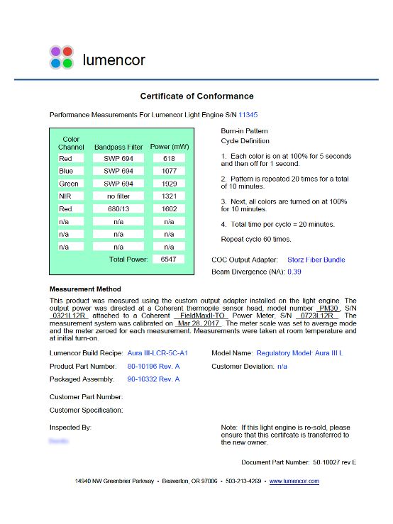
Warning: DO NOT turn on the light without the output end of the light guide safely directed into an enclosed
optical path. DO NOT point the light output directly onto any flammable or burn-susceptible material. This
includes all animal or vegetable tissues, plastics, fabrics, paper and liquids.

Avertissement: NE PAS allumer la lumière sans l'extrémité de sortie du guide de lumière dirigée en toute
sécurité dans un chemin optique fermé. NE PAS pointer la sortie de lumière directement sur un matériau susceptible
d'être inflammable ou susceptible de brûler. Cela comprend tous les tissus, les plastiques, les tissus, le papier et les liquides
animaux ou végétaux.

RISK GROUP 3

Warning: Possibly hazardous optical radiation emitted from this product. Do not look at operating lamp. Eye injury may
result.

Warning: Infrared (IR) emitted from this product. Do not look at operating lamp.

Warning: UV emitted from this product. Avoid eye and skin exposure to unshielded product.

GROUPE DE RISQUE 3

Avertissement: Infrarouge (IR) émise par ce produit. Ne regardez pas la lampe d'exploitation.

Avertissement: Rayonnement optique Peut-être dangereux émis par ce produit . Ne regardez pas la lampe
d'exploitation. Une blessure oculaire peut entraîner.

Avertissement: UV émis par ce produit . Évitez les yeux et la peau exposition au produit non blindé.

Caution: Use of controls or adjustments or performance of procedures other than this specified herein may result in
hazardous radiation exposure.

Attention: L'utilisation de commandes ou de réglages ou l'exécution de procédures autres que celles spécifiées dans le
présent document peuvent entraîner une exposition à des radiations dangereuses.

AURA (L) Light Engine® Instruction Manual                                                                                       6
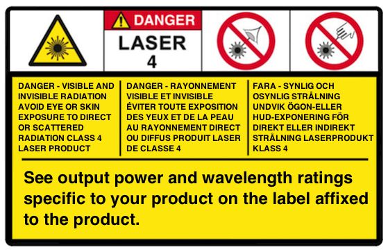
Class 4 Laser Warning

                                                   Warning: This product contains Class 4 laser sources. Avoid eye and
                                                   skin exposure to direct or scattered visible and invisible laser radiation.

                                                   Avertissement: Ce produit contient des sources laser de classe 4.
                                                   Évitez l'exposition des yeux et de la peau au rayonnement laser visible
                                                   ou dispersé visible et invisible.

Laser Sources
Color                      Center Wavelength (nm)             Power                          Beam Divergence
See label located on       300 - 1150 nm. See label           See label located on           Beam divergence shall be
product.                   located on product.                product.                       calculated at the end-system.
                                                                                             Refer to CoC for the light
                                                                                             engine beam divergence (NA)
                                                                                             at the output aperture.

Laser Aperture Warning

                                              or

Warning: Avoid exposure - laser radiation is emitted from this aperture. Do not turn on light engine without first
connecting a light guide to the output aperture. The distal end of this light guide must be coupled into an enclosed
optical path prior to operation. Each operational control and laser aperture that can be separated by 2m or more from a
radiation warning device shall itself be provided with a radiation warning device. Do not exceed 2m without providing a
radiation warning device in accordance with IEC/EN 60825-1:2014.

Avertissement: Évitez l'exposition - le rayonnement laser est émis à partir de cette ouverture. L'ouverture de sortie est
interverrouillée et un guide de lumière doit être connecté et couplé dans un chemin optique inclus avant l'opération.
Chaque commande opérationnelle et l'ouverture laser qui peuvent être séparées de 2 m ou plus à partir d'un dispositif
d'avertissement de rayonnement doivent être munies d'un dispositif d'avertissement de rayonnement. Ne dépassez pas
2m sans fournir un dispositif d'avertissement de rayonnement conformément à la norme IEC/EN 60825-1:2014.

Warning: DO NOT open the unit. There are no serviceable parts inside and opening the light engine enclosure will void
the manufacturer’s warranty.

AURA (L) Light Engine® Instruction Manual                                                                                    7
Avertissement: NE PAS ouvrir l’appareil. Il ne contient aucune pièce réparable et l’ouverture de son boîtier a pour
effet d’annuler la garantie.

Caution: DO NOT set liquids on the light engine. Spilled liquids may damage your light engine.

Attention: NE PAS placer de liquide sur la source lumineuse. Les liquides renversés peuvent endommager la
source lumineuse.

Caution: DO NOT drop the light engine. It contains glass optical components that could be damaged or misaligned
by the shock produced by a drop onto a hard surface.

Attention: NE PAS laisser tomber la source lumineuse. Elle contient des composants optiques en verre
susceptibles d’être endommagés ou désalignés par le choc résultant d’une chute sur une surface dure.

DISCLAIMER: Lumencor shall not be liable for injury to the user or damage to the product resulting from the
AURA (L) Light Engine® being used in a way for which it was not intended and in complete disregard for any
posted safety precautions and warnings.

AVIS DE NON-RESPONSABILITÉ: Lumencor décline toute responsabilité pour les blessures corporelles ou
les dommages au produit résultant d’une utilisation du AURA (L) Light Engine® autre que celle prévue et du
mépris total de les mesures de sécurité et mises en garde affichées.

AURA (L) Light Engine® Instruction Manual                                                                             8
3. Installation and Operating Instructions
3.1 Contents
The AURA (L) Light Engine ships with the following list of standard components: AC Power Cords
1. The AURA (L) Light Engine® engine, configured with 3 to 5 output channels Region Part Number
(colors) and an output adapter for connection to an SMA-terminated optical North America 29-10002
fiber or a liquid light guide (LLG) as documented on the certificate of
Europe 29-10005
conformance (Figure 1).
United Kingdom 29-10004
2. A 24 V/9.2 A DC power supply (Lumencor part number 27-10019). Israel 29-10008
3. A region-specific AC power cord for the power supply (see adjacent table). Australia/New Zealand 29-10024
4. RJ45 ethernet cable.
5. Control key, external gate jumper and remote interlock jumper (Figure 2).
6. Quickstart Guide instruction document (85-10049).
EXAMPLE
Figure 2. External gate jumper, remote interlock jumper, and
control keys. These item are packed in a plastic bag inside
the shipping box. Their functions are described in Section
3.3.1.
Figure 1. Example certificate of conformance (C of C)
for AURA (L) Light Engine. The C of C identifies the
color channels installed in the light engine and the
bandpass filters associated with each channel. Full
(100%) power outputs measured at the terminus of the
liquid light guide (LLG) or optical fiber are recorded in
the third column.
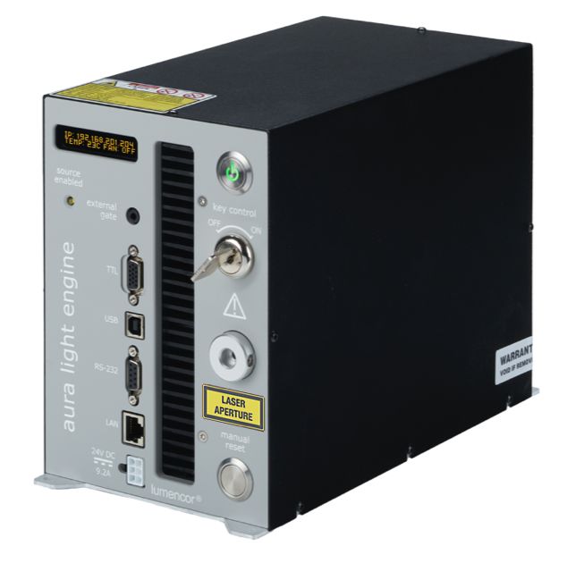
AURA (L) Light Engine® Instruction Manual 9The model name, unique 4- or 5- digit serial number and Status indicator Master power
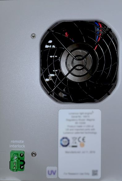
certification markings of the light engine are carried on a label display switch
affixed to the rear panel. Performance specifications for individual
Air intake
light engines are listed on the certificate of conformance included
with the shipping documents e-mailed to the customer (Figure 1).
3.2 Installation
NOTE: Any end-product/system incorporating or coupled to a
Lumencor Light Engine shall be fully evaluated to verify all
Output Coupler, LLG
applicable safety and regulatory compliance requirements prior to
use.
When setting the AURA (L) Light Engine up for use, place the unit
LASER
on a hard surface and avoid blocking or restricting airflow at the air
inlet (front panel; Figure 3) or exhaust ports (rear panel, Figure 4) on
the enclosure. Restricting the airflow will cause the unit to operate DC power
at elevated temperatures and will result in decreased product life input
and/or premature failure.
Figure 3. AURA (L) Light Engine front panel.
The AURA (L) Light Engine must be operated in a non-
condensing environment (dew pointare not field-exchangeable (Figure 3). The 3 mm liquid light guide output coupler incorporates an electrical power interlock switch in the back of the receptacle. The liquid light guide must be fully inserted in the receptacle to activate the interlock. Electrical power supply to the light engine cannot be turned on via front panel power switch until the interlock is activated. After fully inserting the liquid light guide, lock it in position using the set screw on the side of the receptacle to prevent inadvertent disconnection of the light guide during use. 3.3 Operation 3.3.1 Controls and Interlocks The Master Power Switch button on the front panel (Figure 3) turns the electrical power to the unit on or off. A green power indicator embedded in the button is lit when the power supply is connected to the light engine and the power button is in the on position. Initialization of the onboard computer takes about 30 seconds after the master power switch is turned on. When initialization is complete, the status indicator display (Figure 3) will activate. The Key Control (Figure 3) must be in the on position before the lasers can be turned on. The key must be removed and stored in a secure location when the product is not in use. ONLY trained individuals should use and have access to the key. The Master Power Switch button, Key control and Remote interlock (Figure 2) can be used to shut off laser output. The Source Enabled indicator LED (below the status indicator display; Figure 3) provides a warning indication that one or more laser sources are active and emitting invisible and/or visible radiation. The Remote Interlock Connector: (Figure 4) is provided to allow for connection of a remote interlock. When this interlock is open it will shut off laser output. After the interlock has been opened, the Manual Reset button will need to be pushed to resume laser output. WARNING: The Remote Interlock relies on a passive continuity circuit for proper operation. It does not provide a voltage source for external circuitry, nor can external voltage sources be applied to it. UNDER NO CIRCUMSTANCES should a voltage or voltage source be applied to the Remote Interlock circuit. APPLYING A VOLTAGE OF EITHER POLARITY MAY RESULT IN ANOMALOUS OPERATION AND/OR DAMAGE THE PRODUCT, AND COULD IMPACT SAFETY. Customers planning to connect multiple Light Engine remote interlocks together will need to contact Lumencor prior to integration. INTERCONNECTING LIGHT ENGINES OR USING THE REMOTE INTERLOCK INCORRECTLY CAN RESULT IN ANOMALOUS BEHAVIOR AND/OR DAMAGE TO THE PRODUCTS. AVERTISSEMENT : Le verrouillage à distance repose sur un circuit de continuité passif pour un fonctionnement correct. Il ne fournit pas de source de tension pour les circuits externes, et aucune source de tension externe ne peut lui être appliquée. EN AUCUN CAS, une tension ou une source de tension ne doit être appliquée au circuit de verrouillage à distance. L'APPLICATION D'UNE TENSION DE POLARITÉ OU DE POLARITÉ PEUT ENTRAÎNER UN FONCTIONNEMENT ANOMAL ET/OU ENDOMMAGER LE PRODUIT, ET POURRAIT AVOIR UN IMPACT SUR LA SÉCURITÉ. Les clients prévoyant de connecter plusieurs verrouillages à distance Light Engine ensemble devront contacter Lumencor avant l'intégration. L'INTERCONNEXION DE MOTEURS LÉGERS OU L'UTILISATION INCORRECTE DU VERROUILLAGE À DISTANCE PEUT ENTRAÎNER UN COMPORTEMENT ANOMAL ET/OU ENDOMMAGER LES PRODUITS. AURA (L) Light Engine® Instruction Manual 11
WARNING: Prior to turning the light output on, be sure the output end of the liquid light guide or optical fiber is safely
directed into an enclosed optical path (e.g. a beam dump).
AVERTISSEMENT : avant d'activer la sortie de lumière, assurez-vous que l'extrémité de sortie du guide de lumière
liquide ou de la fibre optique est dirigée en toute sécurité dans un chemin optique fermé (par exemple, une décharge de
faisceau).
Note: In the event of ANY normal or abnormal interlock fault condition (including high ESD/EMP/EFT conditions ~2kV)
you MUST clear the latched fault condition, either by pressing the manual reset button or by cycling the power switch.
3.3.2 Start Up
1. Insert the light guide and secure it with the set screw1.
2. Insert the external gate jumper (Figure 2) in the labeled socket on the front panel (Figure 3). Insert the interlock
jumper in the labeled socket in the lower left corner of the rear panel 2 (Figure 4).
3. Insert the control key, turn it to the ON position.
4. Connect the isolated DC power supply to the light engine.
5. Connect the AC power cord to the DC power supply.
6. As soon the DC power supply is energized, the master power button (top right) will automatically light up. The light
engine automatically starts when the power is connected; there is no need to push the master power button 3.
7. Wait 30–45 seconds for the initiation sequence (onboard microprocessor boot-up) to complete. Do not press any
buttons or insert any plugs during this time.
8. When the initiation sequence completes, “LUMENCOR” will flash on front display panel and then be replaced by a
display showing the current light engine IP address, the internal temperature and the fan status. At the same time,
the fan will come on at HI for about 2 seconds and then shut off automatically. The light engine is now ready for use.
Prior to turning the light output on, verify the output end of the liquid light guide or optical fiber is safely directed into
an enclosed optical path (e.g. a beam dump).
Notes:
1 Ensure that the distal end of the light guide or optical fiber is safely directed into an enclosed optical path (e.g.
microscope epi-illuminator or a beam dump) before turning the light output on. If the light engine is equipped with an
output adapter for an SMA-terminated optical fiber, connect the fiber to the output adapter using the integral threaded
sleeve.
2 To enable light output of the AURA (L) Light Engine the external gate jumper, control key, remote interlock jumper, and
Liquid light guide must be inserted.
3 For subsequent start ups, use the master power button to start or shut down the light engine. Shut down can also be
accomplished using the “Shut Down” button in the GUI (Figure 5, left).
3.3.3 Ethernet Connection and Control GUI
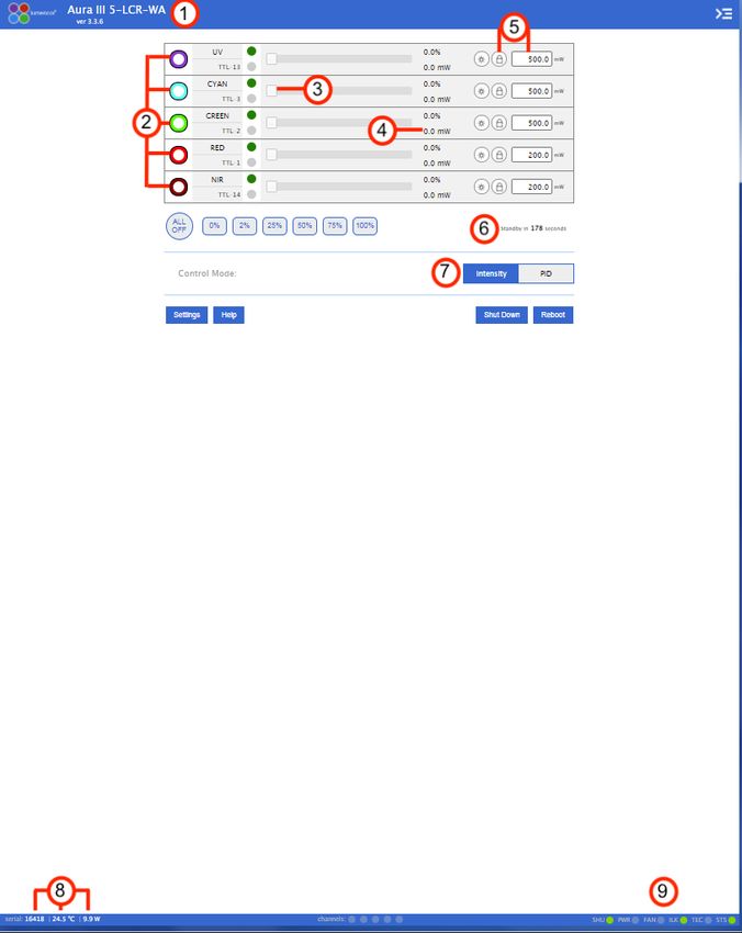
The Web GUI provides a quick and easy way to control the light engine, providing the ability to turn each source on/off
(Figure 5, Control Tab [left], 2), adjust the power of each source independently from off to full power (Figure 5, Control Tab
[left], 3). The GUI also tracks the total on time and the power sensor readings (Figure 5, Control tab [left], 5). To set up
the Web GUI, follow the protocol below:
1. Go to Start menu > Control Panel > Network & Internet and/ or Network & Sharing Center
2. Click Change Adapter Settings
AURA (L) Light Engine® Instruction Manual 123. Right-click on Local Area Connection
4. Click on Properties (in pop-up)
5. Select Internet Protocol Version 4 (TCP/IPv4)
6. Click Properties button
7. Use the following IP addresses:
• IP Address: 192.168.201.201
• Subnet Mask: 255.255.255.0
• Default gate way and DNS Server are OK to leave blank
Figure 5. AURA (L) GUI, Control Tab (Left) and Settings Tab (Right). The GUI is accessed by typing the light engine IP
address (198.168.201.200 in this example) into a web browser. 1) Lumencor light engine model number and software
version, 2) ON/OFF control of source channel, 3) Intensity slider, 4) Live power read out in mW, 5) power regulation
controls: locked in when padlock and input box are grey, 6) Count down timer to Standby mode, 7) Control mode setting,
8) serial number of light engine, live temperature read out, and live power draw read out, 9) Status indicator buttons, 10)
Command line access, 11) System information, 12) TTL controls, 13) Light source on time read out.
8. Connect the RJ45 cable (supplied with the light engine) between the LAN port on the light engine and an Ethernet
port on the computer.
9. Type the Light Engine IP address (Figure 3) into any web browser address bar to access the resident control GUI.
The factory default IP address is 192.168.201.200.
AURA (L) Light Engines that are operating on software version 2.1.19 and above have a standby mode (Figure 5,
Control Tab [left], 6) to conserve power during periods when no active light output generation is required. The light engine
automatically switches into standby mode after a latency period )i.e. after the last light output = OFF command was
issued). The default latency period is 300 seconds (5 minutes), this can be temporarily reset by the user by using the
“WAKEUP” command in the command line (Figure 5, Setting Tab [right], 10). Standby mode is also marked by an
AURA (L) Light Engine® Instruction Manual 13automatic shut-off of the main cooling fan. Standby mode automatically terminates when the next light output = ON
command is issued.
Output power regulation allows users to eliminate variations in light output due to temperature fluctuations and other
environmental factors in photometric and quantitative imaging applications where reproducibility and accuracy are
essential. To use power regulation, a desired power reference value in milliwatts is entered in the onboard control GUI
(Figure 5, Control tab [left]). To activate power regulation, simply click the padlock icon next to the reference power value
(Figure 5, Control Tab [left], 5). Gray shading of the padlock icon and the reference power value shows that power
regulation is active for the selected output channel. When power regulation is active, the intensity setting for the channel
is controlled by the onboard microprocessor, based on feedback from the light engine’s reference photodiode array. The
microprocessor continuously adjusts the intensity setting so that the output power matches the power reference value
set by the user.
3.3.4 Control via Serial ports
AURA (L) Light Engines have two serial ports, labeled USB and RS-232 (Figure 3), which can be set to receive either
LEGACY or STANDARD mode commands. Connection to the computer requires a USB-A-to-USB B cable (29-10058)
or USB-to-RS-232 cable (29-10011). LEGACY commands are limited to controlling on/off switching and intensity
adjustment of individual color channels. Only one of the two ports can be set to LEGACY mode at one time. The
STANDARD mode command set gives access to an extensive panel of operating status reports and configuration
settings in addition to the the basic control functions of the LEGACY command set. A complete listing of STANDARD
mode commands is provided in Lumencor Light Engine Command Reference (Document number 57-10018). Note that
LEGACY and STANDARD mode communications use different serial protocols (9600,8,N,1 and 115200,8,N,1
respectively). Changes to the command mode setting for a serial port can be made via the Settings screen of Web GUI
(Figure 5, right side). Changes are applied instantaneously and are retained between power cycles.
Select the command mode setting for the serial port that is compatible with the light engine device driver in the control
software. This selection is typically found under the “Devices” tab. The COM port address assigned by the computer to
the light engine USB serial port must be correctly registered in control software.
3.3.5 Control From Light Engine Control Pod
1. Connect the AURA (L) Light Engine to pod using USB A-to-USB B cable (29-10058).
2. Open the Web GUI control interface as described in Section 3.3.2.
3. Go to the SETTINGS page (Figure 5, right) in the Web GUI. Ensure the USB port configuration is set to LEGACY
mode and USB 5V is set to ENABLED.
4. The pod must be set in the AURA (L) Light Engine control mode. The light engine control mode setting is shown in
green letters at the bottom of the pod display screen. If the pod is not in the AURA (L) Light Engine control mode,
change the setting by holding down the MODE button on the pod until the light engine selection menu appears.
Move the cursor to “AURA” in the selection menu by turning the pod control knob. Press the MODE button again to
select the AURA (L) Light Engine control mode and return to the main control screen.
5. Follow instructions on Lumencor’s Light Engine Control Pod Operation sheet (54-10036). In brief, press the COLOR
button to select output light output channel, press the MODE button to toggle light output on and off, turn the
control knob to adjust intensity for the current light output channel selection.
AURA (L) Light Engine® Instruction Manual 143.3.6 TTL Control
The TTL Interface provides users with a faster method of switching color TTL Connector Pin Definitions
channel outputs on and off. These can be conveniently addressed using
OUTPUT OUTPUT
an accessory BNC breakout cable (Lumencor part no. 29-10156, Figure Pin# Pin#
COLOR COLOR
6) or an accessory SMB breakout cable (Lumencor part no. 29-10216) RED 1 BLUE 12
connected to the front panel TTL port (Figure 3). As a safeguard against GREEN 2 VIOLET 13
unintended light output when the inputs are initially connected, the TTL CYAN 3 nIR 14
port is disabled. To enable the TTL input, click the Enabled button next TEAL 11 YELLOW 15
to “TTL inputs” in the web GUI under the Settings tab (Figure 5, Settings Gnd 6,7,8,10
Tab [right], 12). The response polarity of the TTL input can be set to Vihigh (min) = 2.0V, Vihigh (max) = 5.5V
positive or negative in the GUI settings tab (Figure 4, right). Changes are Vilow (min) = 0.0V, Vilow (max) = 0.8V
applied instantaneously and are retained between power cycles. The
breakout cable also provides a global shutter input (labeled “shutter”). TTL signals
input to the global shutter will synchronously toggle all currently enabled source
channels on and off.
4. Light Output Characteristics
AURA (L) Light Engines may incorporate different numbers and types of solid state
light sources. Constituent light sources may include LEDs, luminescent light pipes
or lasers. The number of light sources installed and the bandpass filters
associated with each are shown on the Certificate of Conformance included with
the shipping documents e-mailed by Lumencor to the customer. The certificate of
conformance also shows full (100%) power outputs for each source measured at
the terminus of the liquid light guide (LLG) or optical fiber (Figure 1). Not all
sources may be turned on simultaneously. To prevent exceeding the capacity of
the DC power supply, power consumption is tracked by the on-board computer.
If a set limit (see Governor, Figure 5, Settings tab [right], 11) is exceeded, either Figure 6. BNC breakout cable to
by increasing intensity settings for sources that are already on, or by turning on enable TTL triggering
additional sources, commands will be rejected. To clear the error condition,
reduce intensities of sources that are on, or turn off one or more sources.
Light source outputs are refined by bandpass filters. The specifications of these bandpass filters are recorded on the
certificate of conformance as CWL/FWHM where CWL = center wavelength and FWHM = full width at half-maximum
transmission, both measure in nanometers (nm). Bandpass filters are not user-exchangeable and changes require return
of the light engine to Lumencor’s factory for service (see Section 7). Since changing bandpass filters will result in source
output power changes, a new certificate of conformance will be provided as part of this service.
5. Operational Specifications
The AURA (L) Light Engine® must be operated and stored within the environmental conditions specified in the table
below. Performance specifications for individual light engines are listed on the certificate of conformance included with
the shipping documents e-mailed to the customer (see example shown in Figure 1). It is important to retain the
certificate of conformance for reference. In the event that the light engine is sold, the certificate of conformance should
be transferred to the new owner. Certificates of conformance are also recorded in Lumencor’s database and copies can
be requested by e-mail to techsupport@lumencor.com. The request message must include the 4- or 5-digit serial
number of the light engine.
AURA (L) Light Engine® Instruction Manual 15Specification Detail Temperature Operating 32 to 95° F (0 to 35° C) Non-operating -4 to 158° F (-20 to 70° C) Humidity Operating and non-operating 0 to 80% relative humidity, non-condensing¹ Dew Point Operating
No light output in response to          There are 4 interlocks that need to be closed, check all of these:
 source ON command (serial or            1. Control key must be inserted in front panel and turned to “on”
 TTL).                                      position¹.
                                         2. Liquid light guide must be inserted in light output receptacle¹.
                                         3. Remote interlock jumper must be inserted in rear panel¹.
                                         4. External gate jumper must be inserted in front panel (Figure 3).

 Unusually weak fluorescence             Weak fluorescence in all detection channels (DAPI, FITC, TRITC, Cy5 etc)
 signals across all detection            is likely to be due to poor light transmission by the liquid light guide, the
 channels                                collimating adaptor or another distal component of the microscope
                                         optical path and not to abnormally low light output from the light engine.

 Unusually weak fluorescence             1. Check that the light engine power output reading in the Web GUI
 signals in a single detection              (Figure 5) is normal.
 channel (e.g. DAPI)                     2. Check that the dichroic beamsplitter and emission bandpass filter in
                                            the microscope are compatible with light engine excitation filter
                                            specifications shown on the certificate of conformance (Figure 1)².

 High, spatially uniform                 Check that the dichroic beamsplitter and emission bandpass filter in the
 fluorescence background                 microscope are compatible with light engine excitation filter
                                         specifications shown on the certificate of conformance (Figure 1)².

 ¹ Open interlocks for these conditions will be indicated by a red status indicator in the lower right corner of
 the GUI control screen (Figure 5).
 ² Excitation filters are installed in the light engine. Excitation filters installed in the microscope cube are
 generally redundant and it is recommended that they are removed.

7. Customer Support
For technical support of the AURA (L) Light Engine, please contact Lumencor by phone at 503-213-4269 or through
email at techsupport@lumencor.com. Please be prepared to provide the 4- or 5-digit serial number of the light engine.
Any light engine returned to Lumencor for repairs or upgrades requires a pre-issued return material authorization (RMA)
number. To obtain a RMA number, submit the online request form at http://lumencor.com/support/lumencor-rma-
request-form. It is the customer’s responsibility to properly package and safely ship products to Lumencor. Instructions
for shipping will be provided in the e-mail giving notification of the RMA number.

8. Warranty
AURA (L) light engines ® are backed by a 24 month warranty to end users. Warranty coverage starts on the original date
of shipment from Lumencor. Light Engines qualifying for warranty service must be verifiably delivering performance that
is substantially at variance with the levels documented in the certificate of conformance. The light engine must also have
been used and maintained under operating conditions consistent with the specifications given in Section 5, and
observing all the Precautions and Warnings notified in Section 2. This warranty does not extend to light engines that
have been subject to misuse, accident, tampering or improper installation. Accessories including (but not limited to)
liquid light guides, optical fibers, collimators, cables and control consoles are not covered by the warranties attached to
light engines. Please fill out and submit the online warranty registration form. This will facilitate provision of warranty
service should it be required.

AURA (L) Light Engine® Instruction Manual                                                                                     17
Vous pouvez aussi lire