VE Panel Installation and Service Manual - ENGLISH - Victron Energy
←
→
Transcription du contenu de la page
Si votre navigateur ne rend pas la page correctement, lisez s'il vous plaît le contenu de la page ci-dessous
ENGLISH

VE Panel Installation and
    Service Manual

                            Rev 02 03/2021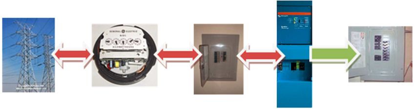
VE Panel Installation and Service Manual

Table of Contents
  1. Safety ................................................................................................................................... 1
         1.1. Safety Symbols .............................................................................................................. 1
         1.2. Important Safety Instructions ............................................................................................... 1
         1.3. General Safety Precautions ................................................................................................ 1
         1.4. Battery Safety ................................................................................................................ 2
         1.5. Service or Repair ............................................................................................................ 2

  2. Introduction ........................................................................................................................... 4
         2.1. Features ...................................................................................................................... 4
         2.2. Compatibility ................................................................................................................. 4
         2.3. Models Available ............................................................................................................ 4
         2.4. Installation Manual .......................................................................................................... 4

  3. Installation ............................................................................................................................. 6
         3.1. Configuration ................................................................................................................. 6
                3.1.1. Planning ............................................................................................................ 6
                3.1.2. Location ............................................................................................................ 6
         3.2. What's In The Box ........................................................................................................... 8
         3.3. Required Materials and Tools .............................................................................................. 8
                3.3.1. Materials ............................................................................................................ 8
                3.3.2. Tools ................................................................................................................ 8
         3.4. Mounting the VE Panel ..................................................................................................... 8
         3.5. Installing the VE Panel to the Inverter/Charger .......................................................................... 9

  4. Wiring ................................................................................................................................. 10
         4.1. General Wiring Requirements and Considerations ....................................................................              10
         4.2. Torque Requirements .....................................................................................................        10
         4.3. Electrical System Wiring Diagrams ......................................................................................         11
         4.4. DC ...........................................................................................................................   17
                4.4.1. DC Wiring Guidelines ...........................................................................................        17
                4.4.2. DC Connections .................................................................................................        18
                4.4.3. Battery Negative .................................................................................................      18
                4.4.4. Battery Positive ..................................................................................................     18
                4.4.5. Shunts ............................................................................................................     18
         4.5. PV ...........................................................................................................................   19
                4.5.1. PV Ground Fault Protection ....................................................................................         20
         4.6. AC ...........................................................................................................................   20
                4.6.1. AC Wiring Guidelines ...........................................................................................        20
                4.6.2. Inverter AC Bypass breaker assembly ........................................................................            20
                4.6.3. AC Connections .................................................................................................        21
         4.7. Equipment Ground ........................................................................................................        22
         4.8. Neutral to Ground Bond ..................................................................................................        23
         4.9. Lightning Arrestor ..........................................................................................................    23
         4.10. Connections required by installer ......................................................................................        24

  5. Operation ............................................................................................................................ 25

  6. Warranty ............................................................................................................................. 26

  7. Sticker Set ........................................................................................................................... 27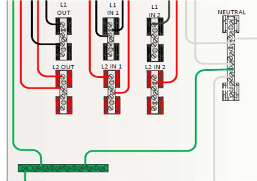
VE Panel Installation and Service Manual

1. Safety

1.1. Safety Symbols
The following safety symbols have been placed throughout this manual to indicate dangerous and important safety instructions.

                        WARNING: This symbol indicates that failure to take a specified action could result in
                        physical harm to the user.
                        AVERTISSEMENT: ce symbole indique que le fait de ne pas effectuer une action spécifiée
                        peut entraîner des blessures physiques pour l'utilisateur.

                        CAUTION: This symbol indicates that failure to take a specified action could result in
                        damage to the equipment.
                        ATTENTION: ce symbole indique que le non-respect d'une action spécifiée peut entraîner
                        des dommages à l'équipement.

                        INFO: This symbol indicates information that emphasizes or supplements important points of
                        the main text.
                        Info: ce symbole indique des informations qui soulignent ou complètent des points
                        importants du texte principal.

1.2. Important Safety Instructions
• SAVE THESE INSTRUCTIONS - These instructions contain important safety and operating Instructions for the VE Panels.
• If you do not fully understand any of the concepts, terminology, or hazards outlined in these instructions, please refer
  installation to a qualified dealer, electrician or installer.
• These instructions are not meant to be a complete explanation of a renewable energy system.
• These instructions are for use by qualified personnel only. Do not perform any servicing or installation other than that specified
  in the operating instructions unless you are qualified to do so. Incorrect installation or servicing may result in a risk of electric
  shock, fire, or other safety hazard.

• CONSERVEZ CES INSTRUCTIONS - Ces instructions contiennent des instructions de sécurité et de fonctionnement
  importantes pour les panneaux VE.
• Si vous ne comprenez pas parfaitement l'un des concepts, la terminologie ou les dangers décrits dans ces instructions, veuillez
  confier l'installation à un revendeur, un électricien ou un installateur qualifié.
• Ces instructions ne sont pas censées être une explication complète d'un système d'énergie renouvelable
• Ces instructions sont destinées uniquement à un personnel qualifié. N'effectuez aucun entretien ou installation autre que celui
  spécifié dans le mode d'emploi, sauf si vous êtes qualifié pour le faire. Une installation ou un entretien incorrect peut entraîner
  un risque d'électrocution, d'incendie ou d'autres dangers pour la sécurité.

1.3. General Safety Precautions
•   All electrical work must be performed in accordance with local and national electrical codes.
•   This product is designed for indoor/compartment installation.
•   Use insulated tools to reduce the chance of electrical shock or accidental short circuits.
•   This unit is provided with integral protection against overloads.
•   Live power may be present at more than one point since an inverter utilizes both DC (batteries, PV, etc.,) and AC (utility or
    generator) power. To reduce risk of electric shock, ensure all DC and AC wiring is disconnected prior to installing or performing
    maintenance on the inverter. Turning off the inverter will not reduce this risk, the inverter must be totally disconnected from all
    sources.
•   Always verify proper wiring prior to starting the inverter.
•   Use only copper wires with a minimum temperature rating of 90°C.
•   Battery cables should be no less than #4/0 gauge for both 24 and 48-volt systems. Crimped and sealed copper ring terminal
    lugs with an m8 (5/16) hole should be used to connect to the DC terminals on the inverter/charger.
•   Torque all AC wiring connections and DC cable connections to the required torque values listed in section 4.3.
•   This equipment is NOT intended for use with life support equipment or other medical equipment or devices.
•   Be sure to comply with all local and national code requirements including National Electrical Code, ANSI /NFPA 70. Use Class
    1 wiring methods for field wiring connections to terminals of a Class 2 circuit
•   Select the wire gauge used based on the protection provided by the circuit breakers/fuses.
•   It is the responsibility of the installer to verify compliance with all applicable codes.
•   Before making any connections verify that the circuit breakers are in the off position including the inverter breaker. Double
    check all wiring before applying power.

Page 1                                                                                                                           Safety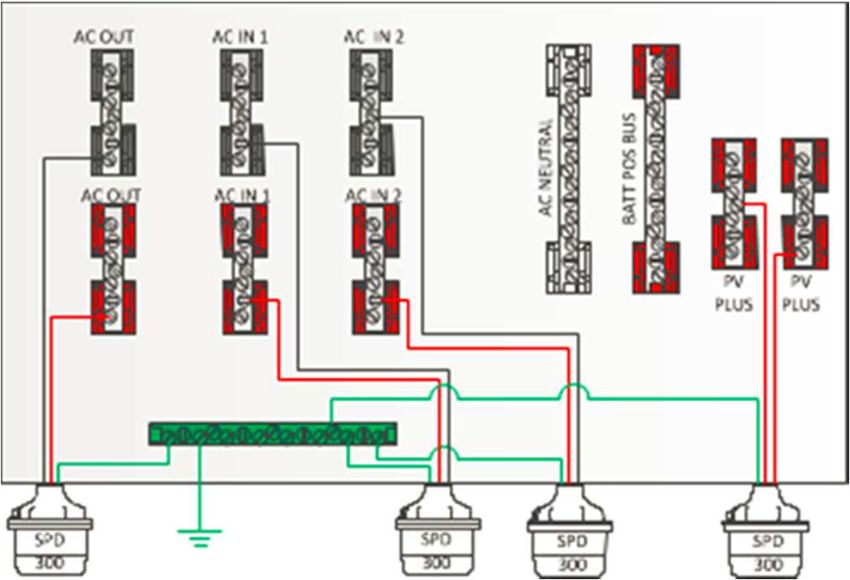
VE Panel Installation and Service Manual

Précautions générales de sécurité

•   Tous les travaux électriques doivent être effectués conformément aux codes électriques locaux et nationaux.
•   Ce produit est conçu pour une installation à l'intérieur / dans un compartiment.
•   Utilisez des outils isolés pour réduire le risque de choc électrique ou de courtcircuit accidentel.
•   Cet appareil est doté d'une protection intégrale contre les surcharges.
•   Une alimentation en direct peut être présente à plus d'un point car un onduleur utilise à la fois une alimentation CC (batteries,
    PV, etc.) et CA (secteur ou générateur). Pour réduire le risque de choc électrique, assurezvous que tous les câbles CC et CA
    sont déconnectés avant d'installer ou d'effectuer des opérations de maintenance sur l'onduleur. La mise hors tension de
    l'onduleur ne réduira pas ce risque, l'onduleur doit être totalement déconnecté de toutes les sources.
•   Vérifiez toujours le câblage approprié avant de démarrer l'onduleur.
•   Utilisez uniquement des fils de cuivre avec une température minimale de 90 ° C.
•   Les câbles de batterie doivent être au moins de calibre # 4/0 pour les systèmes de 24 et 48 volts. Des cosses à anneau en
    cuivre serties et scellées avec un trou m8 (5/16) doivent être utilisées pour se connecter aux bornes CC de l'onduleur.
•   Serrez toutes les connexions de câbles CA et de câbles CC aux valeurs de couple requises.
•   Cet équipement n'est PAS destiné à être utilisé avec des équipements de survie ou d'autres équipements ou dispositifs
    médicaux.
•   Assurez-vous de respecter toutes les exigences des codes locaux et nationaux, y compris le National Electrical Code, ANSI /
    NFPA 70. Utilisez des méthodes de câblage de classe 1 pour les connexions de câblage sur site aux bornes d'un circuit de
    classe 2. Utilisez uniquement un fil AWM de calibre 14-4 / 0. Sélectionnez le calibre de fil utilisé en fonction de la protection
    fournie par les disjoncteurs / fusibles.
•   Il est de la responsabilité de l'installateur de vérifier la conformité à tous les codes applicables.
•   Avant d'effectuer toute connexion, vérifiez que les disjoncteurs sont en position d'arrêt, y compris le disjoncteur de l'onduleur.
    Vérifiez tout le câblage avant de mettre sous tension.

1.4. Battery Safety
• Use insulated tools and be very careful when working around batteries, they can produce extremely high currents if short-
  circuited.
• Read and follow the battery manufacturer’s safety precautions before installing the inverter and batteries. Always verify proper
  polarity and voltage before connecting the batteries to the inverter.
• Remove all jewelry such as rings, watches, bracelets, etc., when installing or performing maintenance on the batteries and
  inverter. A battery can produce a short-circuit current high enough to weld metal jewelry, causing severe burns.
• Never work alone. Always have someone within your line of sight or close enough to come to your aid when working around
  batteries.
• Use proper lifting techniques when working with batteries.
• Batteries are sensitive to changes in temperature. Always install batteries in a stable environment.
• Provide at least 3cm (1 inch) of air space between batteries to provide optimum cooling.

Sécurité de la batterie

• Utilisez des outils isolés et soyez très prudent lorsque vous travaillez autour des batteries, elles peuvent produire des courants
  extrêmement élevés en cas de court-circuit
• Lisez et respectez les consignes de sécurité du fabricant des batteries avant d'installer l'onduleur et les batteries. Vérifiez
  toujours la polarité et la tension appropriées avant de connecter les batteries à l'onduleur
• Retirez tous les bijoux tels que bagues, montres, bracelets, etc., lors de l'installation ou de l'entretien des batteries et de
  l'onduleur. Une batterie peut produire un courant de court-circuit suffisamment élevé pour souder des bijoux en métal,
  provoquant de graves brûlures.
• Ne travaillez jamais seul. Ayez toujours quelqu'un dans votre champ de vision ou assez près pour vous venir en aide lorsque
  vous travaillez autour des batteries.
• Utilisez des techniques de levage appropriées lorsque vous travaillez avec des batteries.
• Les batteries sont sensibles aux changements de température. Installez toujours les piles dans un environnement stable.
• Laissez au moins 3 cm (1 pouce) d'espace d'air entre les batteries pour assurer un refroidissement optimal.

1.5. Service or Repair
•   If service or repair should become necessary, contact Victron Energy.
•   Improper servicing may result in a risk of shock, fire or explosion.
•   To reduce these risks, disconnect all wiring before attempting any maintenance or cleaning.
•   Turning off the inverter will not reduce these risks.
•   Solar modules produce power when exposed to light.
•   When it is not possible to disconnect the power coming from the Photovoltaics (PV) by an external means such as a circuit
    breaker, cover the modules with an opaque material before servicing any connected equipment.

Page 2                                                                                                                           Safety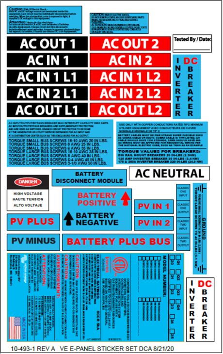
VE Panel Installation and Service Manual

                       WARNING: Incorrect installation or servicing may result in a risk of electric shock,
                       fire, or other safety hazard.

Service ou réparation

•   Si un entretien ou une réparation devenait nécessaire, contactez Victron Energy.
•   Un entretien inapproprié peut entraîner un risque d'électrocution, d'incendie ou d'explosion.
•   Pour réduire ces risques, débranchez tout le câblage avant de tenter toute opération d'entretien ou de nettoyage.
•   La mise hors tension de l'onduleur ne réduira pas ces risques.
•   Lorsqu'il n'est pas possible de déconnecter l'alimentation provenant du photovoltaïque (PV) par un moyen externe tel qu'un
    disjoncteur, recouvrir les modules d'un matériau opaque avant de réparer tout équipement connecté.

                       AVERTISSEMENT: une installation ou un entretien incorrect peut entraîner un risque
                       d'électrocution, d'incendie ou d'autres risques pour la sécurité.

Page 3                                                                                                                     Safety
VE Panel Installation and Service Manual

2. Introduction

2.1. Features
• Includes:
  • Internally pre-wired enclosure.
  • A built-in AC bypass switch with full system current capability, and a DC disconnect breaker for safe and easy isolation for
    servicing of the inverter and/or battery bank.
  • Battery to inverter/charger DC disconnect breaker (250 Amps).
  • Inverter AC input overcurrent protection breakers.
  • DIN mount AC and DC breakers for quick and easy operation.
  • A500A/50mV DC shunt installed for easy connection to battery status monitor.
  • Enclosure and components are UL/CSA certified and designated for indoor use.
  • Configurations available for both single 120 and 230 VAC, 120/240 VAC and 3-Phase systems.
  • DC negative, positive and ground busbars for DC loads and PV arrays included.
  • Mounting provided for DIN rail DC load/disconnect breakers.
  • Integrates directly with Victron Energy’s 3,000 and 5,000 MultiPlus and Quattro inverter/chargers.
  • Knockouts for inverter/charger and battery cables, PV in/out, DC panel mount breakers.

2.2. Compatibility
• The VE Panel (VEP) is designed for the 3kVA and 5kVA MultiPlus and Quattro inverter/chargers.

2.3. Models Available
  Description                                                                            Part Number
  VE Panel 3kVA 120/240 NA Primary 24/48Vdc                                            VEP230121402
  VE Panel 3kVA 120 NA Follower 24/48Vdc                                               VEP230141204
  VE Panel 3kVA NA 3PH Primary 24/48Vdc                                                VEP230161604
  VE Panel 3kVA 230 Export Primary 24/48Vdc                                            VEP230422002
  VE Panel 3kVA 230 Export Follower 24/48Vdc                                           VEP230442004
  VE Panel 3kVA 230 Export 3PH 24/48Vdc                                                VEP230462206

  VE Panel 5kVA 120/240 NA Primary 48Vdc                                               VEP250125402
  VE Panel 5kVA 120 NA Follower 48Vdc                                                  VEP250145204
  VE Panel 5kVA NA 3PH Primary 48Vdc                                                   VEP250165606
  VE Panel 5kVA 230 Export Primary 48Vdc                                               VEP250426002
  VE Panel 5kVA 230 Export Follower 48Vdc                                              VEP250446004
  VE Panel 5kVA 230 Export 3PH 48Vdc                                                   VEP250466206

2.4. Installation Manual
• Use this installation manual to aid in installation.
• The installation of an electrical system such as this, fall under the guidelines of the NEC in the USA. Canadian electrical codes
  have jurisdiction in Canada.
• These instructions are not intended to be used in lieu of these local and federal codes, but rather are used as specific to this
  product.
• You may need to consult with a professional solar installer or electrical inspector when in doubt on code specific questions and
  system installation issues.
• Even though the VE Panel incorporates and simplifies numerous separate electrical circuits into one enclosure, an inverter
  system such as this is still a very sophisticated and somewhat complicated electrical system.

Page 4                                                                                                                Introduction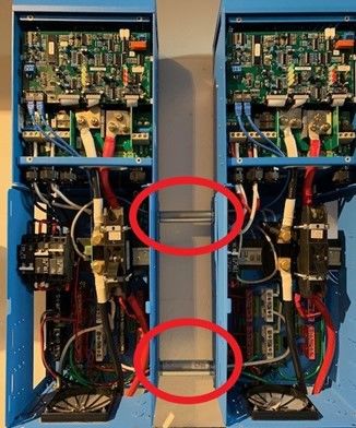
VE Panel Installation and Service Manual

         WARNING: Incorrect installation or servicing may result in a risk of electric shock, fire, or
         other safety hazard.

Page 5                                                                                                   Introduction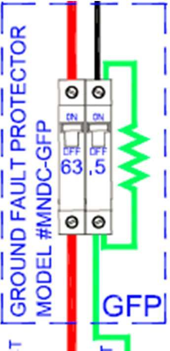
VE Panel Installation and Service Manual

3. Installation

3.1. Configuration
• Installing multiple VE Panels, a trough or gutter below the VE panel is a compliant and effective method for wire management in
  connecting parallel systems.
• Knock outs are provided on the sides and bottom of the VE Panels and could be utilized to run wire and data cables via conduit
  between the systems. Refer to Figures 2 and 3 for examples.

                                            Figure 1 Conduit Interconnection Example

• VE Panel’s in parallel operation can be used with a battery combiner for larger dual Quattro 5k VA inverter/charger systems
  shown in Figure 15.

3.1.1. Planning
• Before proceeding, read the entire Installation section to determine how you are going to install your VE Panel enclosure.

3.1.2. Location
• Refer to the dimensional drawings in Figure 2 and 3 to determine an appropriate area to install the VE Panel enclosure and
  inverter/charger system. The following should be considered:
  • VE Panel shall be mounted vertically.
  • Installed indoors in a clean and dry area that is relatively cool environment.
  • The inverter/charger will pull in air through the intake vents at the bottom of the VE Panel.
  • In order for the inverter/charger to provide full output power and avoid overtemperature conditions, do not cover or block the
    VE Panel enclosure ventilation openings or install it in an area with limited airflow. At the minimum, allow 10cm (4”) of
    clearance to the left and right sides to provide adequate ventilation.
  • The VE Panel enclosure and inverter/charger system should be located as close to the batteries as possible. This is to
    ensure the battery cable length is kept as short as possible. Long DC wires tend to lose efficiency and reduce the overall
    performance of an inverter. However, the VE Panel enclosure, the inverter/charger, and any other equipment that can spark
    (or that corrosion could damage) should not be installed in the same compartment/room as the batteries or mounted where it
    will, depending on battery type, be exposed to gases produced by the batteries. These gases are corrosive and will damage
    this equipment. Also, if these gases are not ventilated and if allowed to collect, they could ignite and cause an explosion.
  • Consult the MultiPlus or Quattro owner’s manual to determine the proper sized inverter/charger to battery cables for the
    distance that is used. However, this cable must not be sized any smaller than the minimum size requirement for the DC
    disconnect breaker in the VEP Panel enclosure. Both VE Panel models require a minimum 0000 (4/0) AWG (107mm²) cable.
  • Do not install the inverter/charger-VE Panel assembly in any area that contains extremely flammable liquids like gasoline or
    propane, or in locations that require ignition-protected devices. Sparks from relays, circuit breakers, etc., could ignite the
    fumes or spills.
  • Do not block access to the front of the VE Panel enclosure. Maintain at least a 1m (36”) clear space in front to access the AC
    and DC wiring terminals and connections inside the enclosure, as they will need to be checked and tightened periodically.
  • Do not mount the VE panel directly above a flooded or sealed lead acid battery bank unless batteries are contained in an
    enclosure with outside ventilation.

Page 6                                                                                                                Installation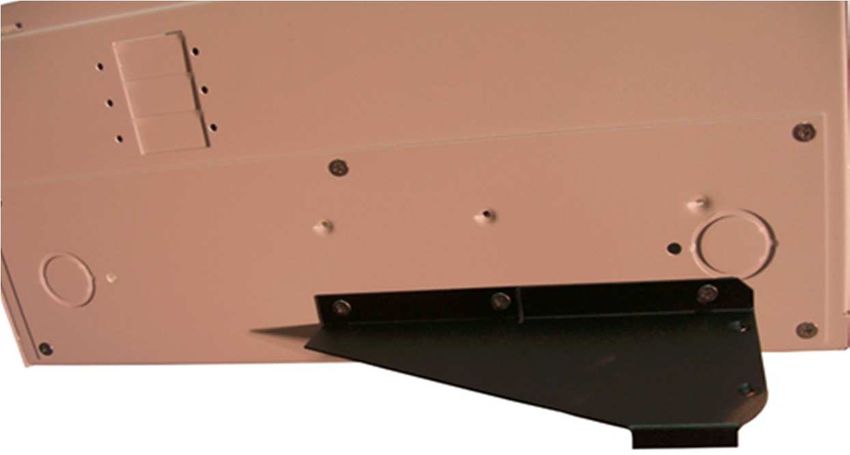
VE Panel Installation and Service Manual

             Figure 2 - 3k VE Panel Dimensions

             Figure 3 - 5k VE Panel Dimensions

Page 7                                              Installation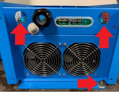
VE Panel Installation and Service Manual

3.2. What's In The Box
•   Internally pre-wired VE Panel assembly
•   Charge Controller Bracket (Victron MPPT’s mount separately)
•   VE Panel Installation Manual
•   Service and user manual
•   Sticker Set

3.3. Required Materials and Tools

3.3.1. Materials
•   Electrical tape
•   Wire ties
•   Conductors/cables for wiring
•   M6 or ¼ inch fasteners

3.3.2. Tools
•   Screwdriver set
•   Insulated pliers
•   Wire cutters/strippers
•   Drill and drill bits for mounting VE panel
•   Pencil or marker
•   Multi-meter
•   Level
•   Ratchet and socket Set
•   Wrench Set
•   Torque wrenches to include:
    • Small Torque wrench for DIN Rail circuit breakers such as 2.5 Nm or 20 inch pounds.
    • Larger torque wrench for battery inverter/charge cables 14Mn or 124 inch pounds.

3.4. Mounting the VE Panel
• The Victron inverter/charger should be mounted first to the wall prior to installing the VE Panel. Pay attention to the total height
  of the system. Refer to the dimensioned drawing in Figure 2 and 3.
• Prior to mounting the MultiPlus or Quattro, to improve airflow/circulation, and to provide easy access to the large chassis
  ground terminal stud, it is necessary to remove the blue fan cover plate. It is required to remove Glands/strain relief on the
  5kVA Quattro to remove the blue fan cover plate, and replace. See Figures 4 through 7.

                                           Figure 4 - 3kVA Blue Fan Cover Plate Installed

Page 8                                                                                                                    Installation
VE Panel Installation and Service Manual
Figure 5 - 3kVA Blue Fan Cover Plate Removed
Figure 6 - 5kVA Blue Fan Cover Plate Installed
Figure 7 - 5kVA Blue Fan Cover Plate Removed
3.5. Installing the VE Panel to the Inverter/Charger
• To install the VE Panel, remove dead front.
• The 4 mounting feet can be accessed through the front of the enclosure to attach to surface with M6 or ¼ inch fasteners.
• Attach to vertical surface and use appropriate fasteners to support at least three times the weight of the panel (each panel is
@17lbs or 8Kg).
Page 9 InstallationVE Panel Installation and Service Manual 4. Wiring 4.1. General Wiring Requirements and Considerations • The AC and DC wires into and out of the VE Panel enclosure must be protected as required by code in NA. This can be done by using jacketed wires or by feeding the wires through conduit. • Use proper clamps or other approved methods for securing the cable/conduit to the enclosure. • Do not mix AC and DC wiring in the same conduit. The VE Panel enclosure is specify approved/designed for both AC and DC wiring. However, where DC wiring must cross AC or vice-versa, try to make the wires at the crossing point 90° to one another. • Use only copper wires with a minimum rating of 150V, 75°C if only 120 VAC power is being used; or, with a minimum rating of 300V, 75°C if 120/240 VAC power is being used. • The equipment grounding conductors must be bare (no insulation), or have green or green with yellow-striped insulation or identification. The hot ungrounded conductor (DC positive/AC hot) is usually red or black. 4.2. Torque Requirements Busbar Torque Values Small Busbar Screws 18 - 10 AWG 6 – 1mm² 20 Inch Pound 2.3N-m Small Busbar Screws 8 AWG 8.36mm² 25 Inch Pounds 2.8N-m Small Busbar Screws 6 AWG 13.3mm² 35 Inch Pounds 4N-m Large Busbar Screws 18 - 10 AWG 6–1mm² 35 Inch Pounds 4N-m Large Busbar Screws 8 AWG 8.36mm² 40 Inch Pounds 4.5 N-m Large Busbar Screws 6-4 AWG 13-21mm² 45 Inch Pounds 5 N-m Large Busbar Screws 3-1/0 AWG 27-54mm² 50 Inch Pounds 5.6 N-m Breaker Torque DC DIN Rail Mounted Breakers 20 Inch Pounds 2.3 Nm AC DIN Rail Mounted Breakers 20 Inch Pounds 2.3 Nm 5A to 100A DC Panel Mounted Breakers 30 Inch Pounds 3.4 Nm Inverter/3.4 Nm 250A Breaker 18 Foot Pounds 24.9 Nm Shunt Torque MidNite Solar PN MNSHUNT 50mV/500amp 180 Inch Pounds 20.4 Nm Victron PN SHU500050100 Shunt 500A/50mV 180 Inch Pounds 20.4 Nm Inverter/Charger Torque Requirements MultiPlus 3k Battery Stud Terminals 97 Inch Pounds 11 Nm AC Terminal Blocks 45 Inch Pounds 5.1 Nm Quattro 5k Battery Stud Terminals 124 Inch Pounds 14 Nm AC Terminal Blocks 62 Inch Pounds 7 Nm Page 10 Wiring
VE Panel Installation and Service Manual

4.3. Electrical System Wiring Diagrams
• Diagrams of the AC and DC wiring for the VE Panel Series enclosure are shown in Figures 8 through 17 and are provided to
  assist you or your system installer.
• Due to the variety of applications and differences in local and national electrical codes, these wiring diagrams should be used
  as general guidelines only.
• They are not intended to override or restrict any national or local electrical codes. The diagrams should not be the determining
  factor as to whether the installation is compliant, that is the responsibility of the electrician and the on-site inspector.

                                             Figure 8 - NA 5kVA Component Locator

                                             Figure 9 - NA 3kVA Component Locator

Page 11                                                                                                                     Wiring
VE Panel Installation and Service Manual
Figure 10 - NA 5kVA Single AC Connection Points
Page 12 WiringVE Panel Installation and Service Manual
Figure 11 - NA 5kVA Single Optional AC2 IN Connection Points
Page 13 WiringVE Panel Installation and Service Manual
Figure 12 - NA 5kVA Dual Stack AC (1 AC Input) Connection Points
Figure 13 - NA 5kVA Dual Stack AC (2 AC Inputs) Connection Points
Page 14 WiringVE Panel Installation and Service Manual
Figure 14 - NA 5kVA 3-Phase AC Connection Points
Figure 15 - NA 5kVA Dual Stack VE Panel Battery Connection Points
Page 15 WiringVE Panel Installation and Service Manual
Figure 16 - Export 3kVA Single VE Panel AC and DC Connection Points
Page 16 WiringVE Panel Installation and Service Manual
Figure 17 - NA 3kVA Single AC and DC Connection Points
4.4. DC
4.4.1. DC Wiring Guidelines
• During normal operation, the terminals, busbars, and electrical components inside the VE Panel enclosure may be energized –
DO NOT TOUCH. Disconnect all power sources before removing the cover
• Even though DC voltage is “low voltage”, significant hazards may be present, particularly from short circuits of the battery
system.
• Before wiring the DC cables, review the safety information at the beginning of this manual and the following information to
ensure a safe and long-lived system.
• Failure to use the proper terminal may cause the connection to heat-up, and may eventually fail or become a fire hazard.
• DO NOT connect the battery cables to the inverter/charger until all wiring is complete and the correct DC voltage and polarity
have been verified.
• When the inverter/charger is installed in a Photovoltaic System, the NEC requires that the DC circuit conductors and
overcurrent devices to the inverter/charger be sized to carry not less than 125% of the inverter/charger's maximum current
rating.
• Crimped and sealed copper compression lugs with a 3/8” hole should be used to connect the battery cables to the DC
disconnect breaker and the DC shunt inside the VE Panel enclosure.
• The battery bank voltage MUST match the DC voltage required by the inverter/charger (i.e., 24-volt battery bank for a 24-volt
inverter/charger), or the inverter may be damaged.
• To ensure the maximum performance from the inverter/charger, all connections from the battery bank to the inverter/charger
through the VE Panel enclosure should be minimized, the exception is the DC circuit breaker in the positive line and the DC
Page 17 WiringVE Panel Installation and Service Manual
shunt in the negative line. Any other additional connection will contribute to additional voltage drops and may loosen during
use.
• All wiring to the inverter/charger and battery terminals should be checked periodically for proper tightness. Refer to the torque
requirements in section 3.1.
4.4.2. DC Connections
• Use Diagrams in section 4.3 to view the DC connection points inside the VE Panel enclosure.
• The VE Panel comes supplied with 4/0 cable for the inverter/charger connections (both 3kVA and 5kVA models).
• Busbars are provided for easy hook up for PV.
4.4.3. Battery Negative
• The battery negative on both the 3kVA and 5kVA version are mounted on the bottom of the shunt shown in the Component
Locater Figures 2 and 3.
• An optional Negative Battery busbar can be placed in the 5kVA model referenced in Component Locator shown in Figures 2
and 3.
4.4.4. Battery Positive
• The battery positive on both the 3kVA and 5kVA models are mounted on bottom of the inverter/charger 250A circuit breaker
shown in the Component Locater shown in Figures 2 and 3.
4.4.5. Shunts
• The VE Panel comes with a standard 50mV/500amp shunt with current sense module option available.
• The standard shunt can be replaced with a Victron shunt and must be ordered separately. For example, a Victron Energy
50mV/500A (part number SHU500050100) or the SmartShunt (part number SHU050150050).
• In a dual VE Panel configuration the supplied shunt will act as a transition point only for the negative follower inverter/charger to
battery.
• When using a battery monitoring shunt in a dual configuration it should be wired as shown in the diagram in Figure 15 using a
Battery Combiner Box such as the MidNite Solar MNBCB 1000/50 and using the 1000A/50mV shunt provided or replacing with
a Victron Energy shunt for battery State of Charge (SOC).
• Note in this configuration the supplied shunts in the VE Panels are for transition of the Negative battery cables only.
Figure 18 - Standard Shunt
Figure 19 - SmartShunt 500A/50mV
Page 18 WiringVE Panel Installation and Service Manual
Figure 20 - Victron Shunt 50mV/500A
4.5. PV
• The VE Panel enclosure is set up to accept numerous controllers using an optional bracket, but Victron MPPTs are not
mounted with the optional bracket. Controllers may be installed on either side of the enclosure using brackets.
INFO: 1 MPPT can be added to either Primary or Secondary VE Panels.
• The bracket is the standard bracket that comes with every VE Panel. If your controller must mount to the opposite side, then
order a MNCCB-Left. This bracket directly accepts the MidNite Classic controller, OutBack MX60, FM60 and FM80. Some
PWM controllers such as the Xantrex C40/C60 and the Morningstar Tristar 60 can also mount to this bracket by adding an
additional mounting hole. The Xantrex MPPT controller does not require a bracket
Figure 21 - Charge Controller Bracket
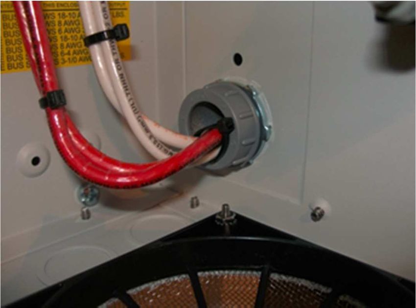
• Wires pass through a 1” conduit knockout in the side plate. Install a 1” Close nipple, three 1” locknuts, and two bushings to
complete the wire passage.
• One of the locknuts is placed between the two enclosures to act as a spacer.
• The VE Panel can accept up to three panel mount breakers on either side and up to seven din rail mount breakers.
• Din rail breakers go up to 63 amps at the present.
• Each charge controller must have a breaker/disconnect coming in from the PV combiner and also a breaker on the output of
the controller. The need for breakers on both sides of the controller is an NEC requirement. For a more complete wiring
diagram see Installer Supplied Connection Diagrams Figure 30.
Page 19 WiringVE Panel Installation and Service Manual
Figure 22 - PV Conduit
4.5.1. PV Ground Fault Protection
• If PV Ground Fault Protection is required a PV Ground Fault Protection (GFP) Assembly can be installed. See Figure 23
Figure 23 - Ground Fault Protection Assembly
4.6. AC
• This section provides information on the AC wiring inside the VE Panel enclosure to/from the inverter, from the incoming AC
source, and to the outgoing AC distribution panel (i.e., inverter/charger sub-panel).
4.6.1. AC Wiring Guidelines
• Before installing any AC wiring, review all safety information.
CAUTION: DO NOT connect the Victron inverter’s output to an AC power source. This
could cause severe damage to the inverter and is not covered under warranty.
4.6.2. Inverter AC Bypass breaker assembly
• The Inverter AC Bypass Switch Breaker allows the inverter loads to continue to be powered by the incoming AC source (utility
or generator) while isolating the inverter or battery system if maintenance or repair is needed.
• This AC Bypass assembly is pre-wired in the VE Panel between the incoming AC source and the inverter load panel (i.e., sub-
panel).
• It connects the incoming AC source to the inverter’s AC loads; either through the “inverter” or directly by “bypassing” the
inverter.
• This bypass switch assembly uses a mechanical slide assembly to prevent both breakers from being ON at the same time, but
both can be OFF at the same time.
Page 20 WiringVE Panel Installation and Service Manual
• This bypass switch is normally set to ‘OFF” (inverter not bypassed), but can be easily moved to “ON” (bypassing the inverter)
allowing the AC loads to continue to be powered while the inverter and/or battery bank is being serviced.
CAUTION: All AC loads should be turned off before switching the bypass switch
breaker.
INFO: When the bypass switch is ON the connected equipment is directly powered
from the AC source (utility or generator), and will go off if the AC source is
disconnected or turned off.
4.6.3. AC Connections
• Use Figures in Section 4.3 to view the AC connection points inside the VE Panel enclosure.
• The VE Panel comes wired with 6AWG wire for all AC circuits for the 3k and 5k versions.
• The output of the inverter terminals are wired to the VE Panel AC output terminal busbars.
• Correctly sized conductors are prewired from the VE Panel breakers to connect to the inverter AC line and neutral input and
output. AC1 in line and neutral, AC2 in line and neutral, and AC1 out line and neutral conductors are marked as such. These
wires also connect to the VE Panel terminal busbars of the same name.
• Installer connections are shown in Figure 30.
• Refer to the list of torque values in section 3.1.
• The 3k and 5k VE Panels are supplied with 2 pole 60 Amp continuous duty rated breakers for the generator input, utility input
and AC input/output bypass switch.
• Most generators come with a UL489 branch circuit output breaker. All main distribution/service entrance panels such as Square
D utilize UL489 branch circuit rated breakers.
• The AC breakers supplied in the VE Panel are supplementary protection listed to UL1077. These breakers are used as
disconnects or switches, but not as branch circuit devices. Branch circuit breakers made for a residential service entrance
panels are typically thermal breakers. These breakers are not allowed under NEC guidelines to normally carry more than 80%
of their rating. That means a 60 amp Square D QO stab in breaker may only be sized for 48 amps continuous power.
• The breakers in the VE Panel are a hydraulic/magnetic variety and are allowed under NEC guidelines to carry full rated current.
The VE Panel comes with 60 amp hydraulic/magnetic breakers.
• Busbars are provided for easy connections from a generator and or the utility and also for an AC sub-panel.
• The AC input and output busbars are also the ideal place to connect lightning or surge arrestors.
• The output busbar must not be connected to the main distribution panel in a utility connected installation. The main utility
connected distribution panel will go dead during an outage. Only circuits connected to the AC output busbar (sub-panel) will
have power during a power outage. Do not try to back feed a utility connected distribution panel from the output of the inverter/
charger.
Figure 24 - Grid Tied Battery Backup Flow Diagram
• The flow diagram in Figure 24 shows AC current flow direction for a battery backed up grid tie system.
• DC current flow is not shown. Note that all loads powered by the inverter must be connected to the AC sub-panel on the right.
Figure 25 * shows AC current flow in an off-grid system.
Page 21 WiringVE Panel Installation and Service Manual
• Figure 25 shows AC current flow in an off-grid system.
• DC current flow is not shown.
• In a utility connected system, only the loads connected to the AC output Subpanel will have power during an outage. The main
service entrance loads will have no power.
INFO: The inverter/charger AC OUT 2 is not supported with the VE Panel.
4.7. Equipment Ground
• The VE Panel comes with a green 4 AWG ground wire.
• The ground chassis lug on the bottom right of the inverter/charger is the same electrical connection as the two inside the wiring
compartment of the 5kVA Quattro. For the 3kVA Quattro and MultiPlus only one ground terminal stud that is located in the
bottom right of the inverter/charger chassis. See Figures 26 and 27.
Figure 26 - 3kVA Ground Connection Point
Figure 27 - 5kVA Ground Connection Points
• You may use this large terminal stud as the one single ground connection to the inverter/charger and then connect all other
grounds to the VE Panel ground bus. The 5kVA has three ground terminal studs are bonded and only one is necessary or as
dictated by Authority Having Jurisdiction (AHJ).
• Since the VE Panel ground, inverter/charger chassis ground and wiring compartment grounds are all at the same potential, you
may use any and all as required although electrical inspectors are used to finding all grounds landing on just one busbar.
• The VE Panel ground bus is the proper place for this single point ground on an off-grid system. Your main distribution panel
ground is the proper AC ground for utility connected systems.
• Use the VE Panel ground bus for the DC grounds in a utility connected system. Inspectors will want to see a separate ground
wire from AC and DC on a utility connected system.
• You can use a single ground wire from the VE Panel for AC and DC for an off-grid installation. Refer to Figure 30 for installer
connection points.
Page 22 WiringVE Panel Installation and Service Manual
4.8. Neutral to Ground Bond
• All AC electrical systems in North America must have an AC Neutral to Earth Ground bonding connection, and only one neutral
to ground connection per system
• A typical distribution panel such as Square D makes this bond by use of a bonding green screw.
• That green screw grounds the neutral bus bar when installed.
• Electrical inspectors are used to looking in the main distribution panel for this electrical bond.
• In a grid tie battery back-up installation, this bond has already been made in the main distribution/service entrance panel.
• Do not make this connection inside the VE Panel when connected to utility service.
• In an off-grid installation where there is no utility connection, the bond should be done inside the VE Panel as shown in Figure
28.
• 6AWG Neutral to Ground bonding wire.
• The bond should be done at the power source and since the VE Panel is central to the power generation, it is considered the
source.
• Some electrical inspectors are used to looking for this bond to be accomplished in the distribution panel. They may ask you to
move it to where they feel comfortable finding it. Don’t fight it. The bond can made in the main distribution panel or VE Panel.
Figure 28 - Neutral to Ground Bond Off-Grid Only
INFO: The neutral to ground relay for the MultiPlus or Quattro must be disabled in
VEConfigure3 or VictronConnect.
4.9. Lightning Arrestor
• The Battery + lightning arrestor has marginal value since the batteries make a pretty large arrestor themselves. See Figure 29.
Figure 29 - Lightning Arrestors
Page 23 WiringVE Panel Installation and Service Manual
4.10. Connections required by installer
• Below is a diagram of all wiring to be done by the installer.
WARNING: All parts within VE Panel are live when energized.
Figure 30 - 5kVA Installer Supplied Connections (3kVA Similar)
Refer to Figures in section 4.3 for connections to MultiPlus or Quattro.
Page 24 WiringVE Panel Installation and Service Manual
5. Operation
• The VE Panel provides you with circuit breakers/disconnects to easily operate and maintain your inverter/battery system.
• These breakers are used as the main power disconnecting means and/or overcurrent protection.
INFO: For information on operating the inverter/charger, refer to its owner’s manual.
• If a short-circuit condition occurs, or if a load is placed on the circuit breaker that is more than its rated capacity, the breaker will
trip OFF.
• Before resetting the breaker, first determine the cause of the overcurrent fault. Then, reset the circuit breaker by turning it all the
way OFF, and then all the way back ON. For proper maintenance and longer life, the circuit breakers should be turned off and
on several times at least once a year. This will help to prevent the contacts inside from sticking together.
INFO: Operating temperature range for the MultiPlus and Quattro inverter/charger: -40
to +65°C / -40 to 150°F (fan assisted cooling) Humidity (non-condensing): max 95%
WARNING: To shut the VE Panel-inverter/charger system OFF completely, all of the
circuit breakers in VE Panel should be switched to the OFF position.
Page 25 OperationVE Panel Installation and Service Manual 6. Warranty Five year limited warranty. This limited warranty covers defects in materials and workmanship in this product, and lasts for five years from the date of original purchase of this product. The customer must return the product together with the receipt of purchase to the point of purchase. This limited warranty does not cover damage, deterioration or malfunction resulting from alteration, modification, improper or unreasonable use or misuse, neglect, exposure to excess moisture, fire, improper packing, lightning, power surges, or other acts of nature. This limited warranty does not cover damage, deterioration or malfunction resulting from repairs attempted by anyone unauthorized by Victron Energy to make such repairs. Victron Energy is not liable for any consequential damages arising from the use of this product. The maximum liability of Victron Energy under this limited warranty shall not exceed the actual purchase price of the product. Page 26 Warranty
VE Panel Installation and Service Manual

7. Sticker Set

                          Figure 31 - Sticker Set

Page 27                                                     Sticker Set
Vous pouvez aussi lire