ELITEpro SP and Quick Start Guide
←
→
Transcription du contenu de la page
Si votre navigateur ne rend pas la page correctement, lisez s'il vous plaît le contenu de la page ci-dessous
Quick Start Guide

       ELITEpro SP™
                           and
 ELOG™ Software

      NEED HELP?

      CALL TECH SUPPORT: 541.388.4774 or 800.388.0770

      IMPORTANT: Do not connect the ELITEpro SP to your
      computer until you have installed ELOG 12b.

       E-MAIL: TECHHELP@DENTINSTRUMENTS.COM

  DENT Instruments | 925 SW Emkay Dr. | Bend, Oregon 97702 USA
Phone 541.388.4774 | Fax 541.385.9333 | www.DENTInstruments.com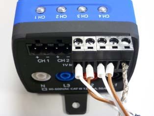
ELITEPRO SP™ SAFETY SUMMARY AND SPECIFICATIONS
This general safety
information is to be used                      Conforms to UL Std 61010-1
by both the Logger                             Certified to CSA Std C22.2 No.
operator and servicing                         61010-1
personnel. DENT
Instruments, Inc.
assumes no liability for         4RH8
user’s failure to comply        E186827
with these safety
guidelines.
The ELITEpro SP™ is an Over-Voltage Category III device. Use approved rubber
gloves with mechanical protection and goggles when operating the device.
CAUTION: This LOGGER may contain life threatening voltages. QUALIFIED
PERSONNEL MUST disconnect all high voltage wiring before using or
servicing the LOGGER.

             Warning: Use of this device in a manner for which it is not intended may impair
             its means of protection.

SYMBOLS ON EQUIPMENT

               Denotes caution. See manual for a description of the meanings.

               When connecting the ELITEpro SP to an AC load, follow these steps in
               sequence to prevent a shock hazard.

                   1.    If possible, de-energize the circuit to be monitored.
                   2.    Connect the CTs to the phases being monitored.
                   3.    Connect the voltage leads to the different phases. Use proper
                         safety equipment (gloves, mask, and protective clothing) as
                         required for the voltages monitored.

               Risk of electric shock. Life threatening voltages may be present. Qualified
               personnel only.

               DO NOT EXCEED 600V Phase to Phase. This logger is equipped to monitor
               loads up to 600V. Exceeding this voltage will cause damage to the logger and
               danger to the user. Always use a Potential Transformer (PT) for loads in
               excess of 600V. The ELITEpro SP is a 600 Volt Over Voltage Category III
               device.

                                              2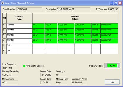
Dispose of properly.

                  IN: 6-10 VDC, 500 mA
                  OUT: 6 VDC, 200 mA maximum

                  USB port

SENSOR LIMITATIONS

                  USE ONLY SHUNTED CURRENT TRANSFORMERS (CTs).

                  Do not use other CTs. Only use shunted CTs with a 333mV maximum output
                  only. Serious shock hazard and logger damage can occur if unshunted CTs
                  are used. The UL listing covers the use of the following DENT Instruments
                  CTs that are UL Recognized and have been evaluated to IEC 61010-1:

                  CT‐HSC‐020‐X (20A Mini), CT‐HSC‐050‐X (50A Mini), CT‐HMC‐0100‐X (100A
                  Midi), and the CT‐HMC‐0200‐X (200A Midi). The use of any other CT will
                  invalidate the UL Listing of the ELITEpro SP.

                  Pulse: Use only "dry contact" non-energized pulse inputs. Use of energized
                  pulse initiators can cause damage to the logger and a potential shock hazard
                  to the user. Wiring must meet 600V AC CAT III rating.

                  Equipment protected throughout by double insulation (IEC 536 Class II). CAT
                  III 80-600 VAC 125mA 50/60 Hz

MAINTENANCE
There is no required maintenance with the ELITEpro SP. Abide by the following items:
Cleaning: No cleaning agents, including water, shall be used on the ELITEpro SP.
Battery Life: The lithium battery is only used to maintain the date and clock settings during power
failure and has a life expectancy of greater than 10 years. Contact DENT Instruments for service.
No accessories are approved for use with the ELITEpro SP other than those specified in the DENT
Instruments product literature and price sheets.
If the logger appears damaged or defective, first disconnect all power and sensors. Call or email
technical support for assistance.
DENT Instruments
Bend, Oregon USA
Phone: 541.388.4774
DENTinstruments.com
Email: techhelp@DENTinstruments.com

                                                 3
ELITEPRO SP™ RÉSUMÉ DE SÉCURITÉ ET SPÉCIFICATIONS
Cette information de
sécurité est destinée à être Conforme à UL Std 61010-1
utilisée à la fois par Certifié CSA Std C22.2 No. 61010-1
l'opérateur de l'enregistreur
et le personnel de service.
DENT Instruments, Inc
n'assume aucune
responsabilité pour 4RH8
l'utilisateur qui ne respecte E186827
pas les directives en matière
de sécurité.
Le ELITEpro SP est un appareil de surtension de catégorie III. Utiliser des gants en caoutchouc
approuvé avec protection mécanique et des lunettes lors de l'utilisation de l'appareil.
ATTENTION: Ce LOGGER peut contenir de hautes tensions qui peuvent être dangereuses. UN
PERSONNEL QUALIFIÉ DOIT débrancher tous les câbles à haute tension avant d’utiliser ou de
réparer du LOGGER.
Attention: L'utilisation de cet appareil d'une manière pour laquelle il n'est pas
destiné peut annuler ses moyens de protection.
SYMBOLES DES EQUIPEMENTS
Signifie prudence. Voir le manuel pour une description de la signification.
En faisant la connexion du ELITEpro SP à une prise de courant alternatif, suivez
ces étapes en ordre pour empêcher un risque de choc.
1. Décharger le circuit à contrôler.
2. Connectez le TC aux phases à surveiller.
3. Connectez les fils de tension à des phases différentes. Utiliser des
équipements de sécurité (gants et des vêtements de protection) qui sont
nécessaires pour les tensions surveillées.
Indique haute tension. Risque de choc électrique. Hautes tensions peuvent
être présentes qui mettent la vie en danger. Personnel qualifié uniquement.
NE PAS DEPASSER 600V Phase à Phase. Ce compteur peut contrôler les
charges jusqu'à 600V. Le dépassement de cette tension peut causer des
dommages à l'appareil et du danger pour l'utilisateur. Utiliser toujours le
potentiel transformateur (PT) pour des charges de plus de 600V. Le ELITEpro
SP est un appareil à 600 V de surtension de catégorie III.
4Se débarrasser de correctement.
IN: 6-10 VDC, 500 mA
OUT: 6 VDC, 200 mA maximum
USB port
LIMITATIONS DE DÉTECTEUR
UTILISEZ SEULEMENT TRANSFORMATEURS DE COURANT (TC) SHUNTÉE.
N’utilisez pas d'autres TC. Utilisez seulement des TC shuntée avec une
puissance maximale 333mV. Un sérieux risque de décharge électrique et des
dommages à l'enregistreur peut se produire si des TC pas shuntée sont
utilisés. Utiliser seulement les CTs des DENT Instruments suivants qui sont
énumérés jusqu'au 600V/CATIII.
CT‐HSC‐020‐U,CT‐HSC‐050‐U,CT‐HMC‐0100‐U,CT‐HMC‐0200‐U
Impulsion: n'utilisez que "contact sec" impulsion intrants non charger.
Utilisation de impulsion initiateurs charger peut causer des dommages à
l'enregistreur et une décharge électrique potentielle pour l'utilisateur. Il faut
que l'installation électrique satisfasse l'évaluation de 600V AC CATIII.
L'équipement protégé en double isolation (IEC 536 Classe II). CAT III 80-600
VAC 125mA 50/60 Hz
Entretien
Il n'y a aucun entretien requis avec le ELITEpro SP. Respectez les points suivants:
Nettoyage: Aucun agents de nettoyage, y compris l'eau, doit être utilisé sur le ELITEpro SP.
Espérance de Vie de la Batterie: La pile au lithium est utilisée uniquement pour maintenir les
paramètres de date et d'heure en cas de coupure de le courant et a une espérance de vie de plus
de 10 ans. Contactez DENT Instruments pour le service.
Pas d'accessoires approuvés pour une utilisation avec le ELITEpro SP sauf ceux spécifiés par DENT
Instruments dans ses documentations sur les produits et également sur les prix.
Si le compteur semble endommagé ou défectueux, tout d'abord déconnecter le pouvoir de
l'appareil. Alors s'il vous plaît appelez 541.388.4774 ou contacter par courriel l'assistance technique
pour obtenir de l'aide.
DENT Instruments
Bend, Oregon USA
Phone: 541.388.4774
DENTinstruments.com
Email: techhelp@DENTinstruments.com
5ELITEPRO SP™ TECHNICAL SPECIFICATIONS
Specification Description
Single Phase-Two Wire, Single Phase-Three Wire, Three Phase-Four Wire
Service Types
(WYE), Three Phase-Three Wire (DELTA)
80-600VAC (80-800VDC), Line-to-Line : 1-600 (1-800 VDC) with External
Voltage Channels
Power
Current Channels Uses voltage output CTs (0-333 mVAC) for maximum safety
Maximum Current
Channel Input 0‐666 mVAC or 0‐1.0VDC
Voltage
Measurement
True RMS using high-speed digital signal processing (DSP)
Type
Line Frequency DC/50/60/400Hz
Waveform
12 kHz
Sampling
Channel Sampling 200 samples/cycle at 60Hz
Rate
240 samples/cycle at 50Hz
(internal
sampling) 30 samples/cycle at 400Hz
The default integration period is fifteen minutes. The choices are 1, 3,
15, 30 seconds; 1, 2, 5, 10, 15, 20 and 30 minutes; 1 and 12 hours; 1 day.
This tells the logger at what time intervals data is to be stored in the
memory. For example, if the integration period is set for 30 minutes and
average watts is being monitored, then every 30 minutes the logger
Data Interval
records the average power use (watts) for that channel over the
preceding 30 minute interval, based on approximately 14,400
measurements of the monitored power draw. If Maximum (and/or
Minimum) values are being recorded the highest (and/or lowest) of
those 14,400 readings are also saved.
Volts, Amps, Amp-Hrs (Ah), kW, kWh, kVAR, kVARh, kVA, kVAh,
Measurements Displacement Power Factor (dPF). All parameters for each phase and for
system total. 1
Accuracy Better than 1% (Specification Description
Pulse Output Open collector 75 mA maximum current, 5 Hz maximum frequency
Communication
USB (Standard) USB standard. 1.8 M (6 FT) A-to-B USB Cable (included)
ETHERNET Standard RJ-45 Connector supports 10/100 MB Ethernet over Cat 5 or
(Standard) better. Configure for DHCP or Static IP address.
BLUETOOTH®
Internal antenna: typical conditionsMinimum System Requirements
Operating System Windows® 7 (32 or 64 bit),Windows 8, Vista (32 or 64 bit) or XP
Processor Pentium Class 1 GHz or more recommended
Hard Drive 50 MB minimum available
Communications
One USB
Port
CD Drive CD or DVD drive required for software installation
1
For 400Hz Volts, Amps, Amp-Hrs (Ah), kW, kWh, kVA, kVAh only
2
Better than 2% at 400Hz
8QUICK START GUIDE
The Quick Start Guide quickly gets you set up and operating with the new ELITEpro SP ™ and ELOG
12b software and is recommended for those that have experience with DENT Instruments or are
familiar with power measuring products and procedures.
To set up the ELITEpro SP for any monitoring session the following items must be completed:
1) Current Transformers (CTs) must be connected to one or more of the channel inputs (unless
doing voltage-only measurements).
2) Line voltage connections must be made for any voltage or power measurements both for
measurement purposes and to power the ELITEpro SP.
3) A Setup Table that tells the meter how and what to measure must be created in the ELOG
software and loaded into the ELITEpro SP.
The information contained in the following section is provided as an example on how to set up a
single phase, 2-wire power measurement session using the ELITEpro SP and ELOG software. Use
this as a guide for your own monitoring project.
DID YOU KNOW? To complete this Quick Start you do not need to have the ELITEpro SP
connected to an actual load. You can do a mock setup at your desk to review how the
software and logger work together.
Install the ELOG 12b Software and the USB Driver
1) Install the ELOG Software onto your computer.
a) Insert the ELOG CD into your computer. The installation will run automatically. If it does
not, browse to the CD and locate the ELOG12Installer.exe program and double-click.
b) Perform the setup steps onscreen. DID YOU KNOW? If your computer
has multiple USB ports, Step 2
2) Install the ELITEpro SP driver on your computer. must be done for each USB port
the ELITEpro SP is plugged into.
a) Connect the USB cable to a USB port on your
computer, inserting the other end in the USB
port on the ELITEpro SP (Hint: Look for this USB symbol: ). If a USB cable is to be
used inside an electrical panel it must be rated to the appropriate voltage or wrapped in
an appropriately rated insulating sleeve. The DENT-supplied cable does not meet this
requirement without an insulating sleeve.
9b) Perform the setup steps onscreen. You must allow ELOG to install the driver for the
ELITEpro SP to work correctly.
c) If the driver installation fails, see the Troubleshooting Driver Installation section of the
ELOG 12B Operator’s Guide.
3) Set the computer aside and proceed with the next section.
Set Up the ELITEpro SP
1) Connect the Current Transformers (CTs) to the wires of the load you are measuring. Orient
the CT so that the arrow on the CT case points towards the load.
NOTE: Use only inherently safe 333mV output CTs supplied by DENT. Never use current output CTs.
The UL listing covers the use of the following DENT Instruments CTs that are UL Recognized and
have been evaluated to IEC 61010-1:
CT‐HSC‐020‐X (20A Mini), CT‐HSC‐050‐X (50A Mini), CT‐HMC‐0100‐X (100A Midi), and the CT‐HMC‐
0200‐X (200A Midi). The use of any other CT will invalidate the UL Listing of the ELITEpro SP.
2) Make your voltage connections (L1, L2, and N). In this scenario, L3 is not used and may be set
aside.
3) Connect the Current Transformers to the ELITEpro SP.
Connect the CTs to the black (Phoenix-style) connectors on the ELITEpro SP’s end panel. Start with
the left-most pair of connections which is Channel One.
The high (+) wire of the CT (the white, banded, or numbered wire depending on CT type)
should go to the left (+) screw terminal of each channel input.
The low (-) CT wire (the black or unbanded wire) should go into the right (-) screw
terminal of the channel input.
If you are using RōCoil CTs, be sure to connect the bare wire to the “S” (shield) screw
terminal. This reduces interference and improves the accuracy of the CT.
10Negative Positive
Shield
Shield Wires from DENT RoCoil
CTs connected to ELITEpro SP
4) Connect the L1, L2, and N voltage leads to the ELITEpro SP.
Sometimes when connecting the L1 and L2 leads a small spark
may be noted. This is normal and will not damage the meter.
Communicate with the ELITEpro SP
1) Double-click on the ELOG 12b shortcut on the Windows® desktop. (ELOG 12b is compatible
with Windows 7 (32 and 64 bit), Windows 8 (32 and 64 bit), Vista (32 and 64 bit), and XP, but
not older versions of Windows.)
2) Connect the PC to the ELITEpro SP using a
USB cable. DID YOU KNOW? “Friendly Ports™”
enable you to see exactly where the
NOTE: The ELITEpro SP automatically connects to ELITEpro SP is connected to your PC in
the PC. If it does not, choose the correct location the event other devices are connected.
from the Ports drop-down menu. For more
information regarding Friendly Ports™, see the
Communicating with the ELITEpro SP content in Section 1 of the manual.
3) Set up the ELITEpro SP for a Single Phase, 2-Wire Load.
11Create a Setup Table
In this step you will create a Setup Table that will tell the ELITEpro SP what to measure, how often,
etc.
1) Select File > New > Setup Table File and click OK.
When your computer is connected to an ELITEpro SP, the ELOG software assumes the new setup
file is for the connected device. Selecting New displays a Setup Table with the default parameters.
If no ELITEpro SP or other logger is connected to the computer, the Select A Setup Table Type
dialog box displays.
2) In the Quick Setups location of the dialog box, click the Single Phase 2 Wire speed button
. The CT Selection dialog box displays for you to enter CT values and type. Click OK.
3) Enter the following information:
Set Data Interval to 1 Minute (or other as desired).
Set the Line Frequency to 50Hz or 60Hz.
(Optional) enter “Quick Start Setup” in the Setup Table Name.
If you did not choose/change values in the CT Selection window, enter the current
transformer (CT) value corresponding to the selected CT if different from the default
value of 100A. The CT value is the nominal maximum input (primary) rating of the CT in
Amps and is printed on the CT.
Input the phase shift (if known and if different from the default value of 1.1°) for the
selected CT.
(Optional) Click in the box beside (Channel 1) Name and type “110V Load”.
Click the down arrow to the right of the Volts field and click Average (or other
parameters to be recorded as desired). Repeat the selection for Amps, kW (kilowatts),
kVA (kilovolt-amps), PF (power factor), and kVAR (kilovolt-amps reactive). You can
choose any combination of values to record: Average, Minimum, Maximum, and
Integrated average (e.g., kWh).
4) Select File > Save As… to save the Setup Table to the computer’s hard drive. Name the table
"Sample" and then click Save.
125) After connecting to the logger, click on one of
the SEND SETUP TABLE to Logger command
buttons on the Setup Table screen. Separate
buttons are available at the top and lower left of the Setup Table screen. Sending a new Setup
Table to the logger deletes any data still stored in the logger. ELOG 12b displays the following
dialog box to ensure desired data is not lost:
6) Click Send SUT and Delete Data. This loads the new Setup Table into the meter and clears the
data in the logger. The Logging is now ON dialog box briefly displays.
-or-
Click Download Data then Send SUT. The Select A Directory and A Name… dialog box
displays. Enter the name and location for the Setup Table data file. After the data is
downloaded to the PC and saved, ELOG automatically sends the new Setup Table to the
meter and starts logging.
-or-
Click Cancel.
ELOG automatically initiates logging when a Setup Table is downloaded to the Logger unless the
Data Logging delayed start time is being used.
View and Retrieve Logger Data
1) Select Logger > Display Real-Time Values > Show As Text to view the real-time values
measured by the logger.
Allow the logger to collect several minutes of data. Collected data can be saved as an .elog file on
the hard drive.
132) Select Logger > Retrieve Data From Logger…
a) Enter a data file name and folder to save the data or use the defaults.
b) Click Save. The data is retrieved from the logger and when finished, the downloaded
data displays automatically.
3) Select Data > Data File Summary to view a text summary of the data. Select Data > Create
New Graph… command to make graphs of the data.
DID YOU KNOW? The ELITEpro SP is not powered by an internal battery, unlike previous
generations of ELITEpro instruments. Instead, the ELITEpro SP can be powered one of three
ways:
1. Line Power: Powering the logger happens automatically when the L1 and L2
voltage connections are made. Normally the logger is powered in the field
during the course of a measurement project.
2. USB Connection: The logger is also powered off the USB connection while it’s
connected to a computer. This is ideal for when you’re configuring the logger for
a new project.
3. Wall Power: Power can also be supplied using an optional wall transformer. This
may be necessary when taking current-only measurements.
For more information on powering the ELITEpro SP, please consult the ELITEpro SP manual
which can also be found under the “Help” menu in ELOG or on the DENT Instruments
website.
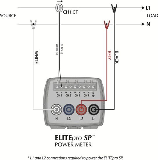
14ELOG QUICK SETUP
The following diagram shows how to connect the ELITEpro SP CT and voltage leads and configure
ELOG’s Setup Table for the single phase, 2-wire power measurement session.
Single Phase, 2-Wire
As an example, configure the Setup Table as follows:
15Single Phase, 2-Wire Setup Table in ELOG 12b
16DENT INSTRUMENTS WARRANTY STATEMENT
Seller warrants to Buyer that the products or services are free from substantial defect in material
and workmanship under normal use given prior installation and maintenance for the period of 12
months after delivery. (SMARTloggers™ are warranted for a period of 36 months after delivery.
PowerScout instruments are warranted for a period of 60 months after delivery.)
Buyer will promptly notify Seller of any defect in the product or service. Seller or its agent will have
the right to inspect the product or workmanship on Buyer’s premises. Seller has the option to: (a)
repair, replace or service at its factory or on Buyer’s premises the product or workmanship found
to be defective; or (b) credit Buyer for the product or service in accordance with Seller’s
depreciation policy. Refurbished material may be used to repair or replace the product. Products
returned to Seller for repair, replacement or credit will be shipped prepaid by Buyer.
Limitation of Warranty
CORRECTION OF DEFECTS BY REPAIR, REPLACEMENT, SERVICE OR CREDIT WILL BE AT SELLER’S
OPTION AND CONSTITUTE FULFILLMENT OF ALL OBLIGATIONS TO BUYER FOR BREACH OF
WARRANTY.
Seller assumes no warranty liability with respect to defects in the product caused by: (a)
modification, repair, installation, operation or maintenance of the product by anyone other
than Seller or its agent, except as described in Seller’s documentation; or (b) the negligent or
other improper use of the product.
Other manufacturers’ equipment purchased by Seller and resold to Buyer will be limited to
that manufacturers’ warranty. Seller assumes no warranty liability for other manufacturers'
equipment furnished by Buyer.
No agent, distributor, or representative is authorized to make any warranties on behalf of
Seller or to assume for Seller any other liability in connection with any Seller product or
service.
Disclaimer of Warranty
Buyer understands and agrees as follows:
THE ABOVE WARRANTY REPLACES ALL OTHER WARRANTIES, EXPRESSED OR IMPLIED, & ALL OTHER
OBLIGATIONS OR LIABILITIES OF SELLER, INCLUDING ANY WARRANTIES OF MERCHANTABILITY AND
FITNESS FOR A PARTICULAR PURPOSE. ALL OTHER WARRANTIES ARE DISCLAIMED AND EXCLUDED
BY SELLER.THE FOREGOING WILL BE THE SOLE AND EXCLUSIVE REMEDY WHETHER IN CONTRACT,
TORT, OR OTHERWISE, & SELLER WILL NOT BE LIABLE FOR INJURIES OR DAMAGES CAUSED BY THE
GROSS NEGLIGENCE OF SELLER. THIS LIMITATION APPLIES TO ALL SERVICES AND PRODUCTS
DURING AND AFTER THE WARRANTY PERIOD.
17Limitation of Remedies
IN NO EVENT WILL SELLER BE LIABLE FOR ANY SPECIAL, INCIDENTAL OR CONSEQUENTIAL
DAMAGES OR COMMERCIAL LOSSES EVEN IF SELLER HAS BEEN ADVISED OF THE POSSIBILITY
THEREOF.
General Provisions
A. Seller reserves the right to subcontract any obligation hereunder.
B. No waiver will be valid unless in writing and no waiver granted will release Buyer from
subsequent strict compliance herewith.
C. Seller is not liable for failure or delay in fulfilling its obligations under these Terms and
Conditions due to causes beyond its reasonable control.
D. The laws of the State of Oregon, U.S.A. will apply to all transactions hereunder. Any action
hereunder will be brought in Deschutes County, in the State of Oregon, U.S.A. Any claim, except
for nonpayment, will be brought within one year of product shipment or completion of services
and Buyer will be liable for any collection costs or attorney fees.
E. Claims for non-conforming orders must be submitted within 30 days from shipment date.
F. These Terms & Conditions together with Seller’s Order Acknowledgment constitute the entire
agreement between the parties with respect to the subject matter hereof & supersede any prior of
contemporaneous agreement or representation written or oral. Any amendment hereto must be
written and signed by Seller.
Service and Support for DENT Instruments Products
Before calling, remember that many questions are answered in the Operator's Guide for your
product. Furthermore, there is extensive product information on the website. In the event that you
have a problem with your DENT product that you cannot resolve, please note the following
information. Before contacting DENT Tech Support, note the Model Name and Serial Number for
your product. You should also be prepared to list the hardware and software details of your PC and
related equipment.
CONTACT DENT INSTRUMENTS TECHNICAL SUPPORT
541.388.4774 or 800.388.0770
TECHHELP@DENTINSTRUMENTS.COM
WWW.DENTINSTRUMENTS.COM
18Vous pouvez aussi lire