SK-156P-A1 User Manual - MicroTouch
←
→
Transcription du contenu de la page
Si votre navigateur ne rend pas la page correctement, lisez s'il vous plaît le contenu de la page ci-dessous
User Manual

SK-156P-A1
Slimline Kiosk Touch Monitor
About This Document

No part of this publication may be reproduced, transmitted, transcribed, stored in a
retrieval system, or translated into any language or computer language, in any form or
by any means, including, but not limited to, electronic, magnetic, optical, chemical,
manual, or otherwise without prior written permission of MicroTouchTM a TES Company.

The information in this document is subject to change without notice. MicroTouchTM a
TES Company makes no representations or warranties with respect to the contents
herein, and specifically disclaims any implied warranties of merchantability or fitness for
a particular purpose. MicroTouchTM a TES Company reserves the right to revise this
publication and to make changes from time to time in the content hereof without
obligation of MicroTouchTM a TES Company to notify any person of such revisions or
changes. Windows is a registered trademark of Microsoft, Inc. Other brand or product
names are trademarks of their respective holders.

1
Compliance Information
For FCC (USA)
This equipment has been tested and found to comply with the limits for a Class B digital
device, pursuant to part 15 of the FCC Rules. These limits are designed to provide
reasonable protection against harmful interference in a residential installation. This
equipment generates, uses, and can radiate radio frequency energy, and if not installed
and used in accordance with the instructions, may cause harmful interference to radio
communications. However, there is no guarantee that interference will not occur in a
particular installation. If this equipment does cause harmful interference to radio or
television reception, which can be determined by turning the equipment off and on, the
user is encouraged to try to correct the interference by one or more of the following
measures:
• Reorient or relocate the receiving antenna.
• Increase the separation between the equipment and receiver.
• Connect the equipment into an outlet on a circuit different from that to which the
    receiver is connected.
• Consult the dealer or an experienced radio/TV technician for help.

This device complies with part 15 of the FCC Rules. Operation is subject to the following
two conditions: (1) this device may not cause harmful interference, and (2) this device
must accept any interference received, including interference that may cause undesired
operation.

For IC (Canada)
CAN ICES-3(B)/NMB-3(B)

For CE (EU)
The device complies with the EMC Directive 2014/30/EU and Low Voltage Directive
2014/35/EU

2
Renseignements relatifs à la conformité
Pour la FCC (États-Unis).
Ce matériel a fait l’objet d’essais qui ont déterminé qu’il respectait les limites d’un appareil
de classe B selon la partie 15 des règlements de la FCC. Ces limites sont établies pour
assurer une protection raisonnable contre les parasites nuisant à une installation
résidentielle. Ce matériel génère, utilise et peut émettre des ondes radio électriques, et
lorsqu’il n’est pas installé et utilisé selon les instructions, peut causer des parasites
nuisant aux communications radio. Il n’y a toutefois aucune garantie qu’il n’y aura pas de
parasites dans une installation en particulier. Si ce matériel cause des parasites à la
réception d’ondes radio ou de télévision, ce qui peut être déterminé en l’éteignant et en
l’allumant, l’utilisateur est invité à essayer de corriger le problème des parasites par l’une
ou l’autre des mesures suivantes :
• Réorienter ou déplacer l’antenne de réception.
• Augmenter la distance entre le matériel et la réception.
• Brancher le matériel dans une prise sur un autre circuit que celui où le récepteur est
branché.
• Consulter le distributeur ou un technicien radio ou TV expérimenté pour des conseils.
L’appareil respecte la partie 15 des règlements de la FCC. Le fonctionnement doit
respecter les deux conditions suivantes : 1) cet appareil ne doit pas causer de parasites et
(2) cet appareil doit accepter tous les parasites reçus, notamment ceux pouvant causer un
fonctionnement non voulu.
Pour Industrie Canada
Norme canadienne NMB-3(B)
Pour la CE (UE)
L’appareil respecte la directive 2014/30/UE relative à la compatibilité électromagnétique et
la directive 2014/35/EU sur les limites de basse tension
3Usage Notice
! Warning - To prevent the risk of fire or shock hazards, and do not
expose the product to moisture.
! Warning - Please do not open or disassemble the product as this may
cause electric shock.
! Warning - Power cord shall be connected to a socket-outlet with
earthing connection.
! Warning - The cable cover cannot be removed under normal use
conditions.
! Warning - Stability Hazard. The touch monitor may fall, causing
serious personal injury or death. To prevent injury, this
touch monitor must be securely attached to the wall in
accordance with the installation instructions.
Precautions
Please follow all warnings, precautions and maintenance as recommended in this user’s
manual to maximize the life of your unit.
Do:
▪ Turn off the product before cleaning.
▪ Use a soft cloth moistened with mild detergent to clean the product housing.
▪ Use only the qualified power adapter that comes with your device.
▪ Disconnect the power plug from AC outlet if the product is not going to be used for an
extended period of time.
Don’t:
▪ Do not use abrasive cleaners, waxes or solvents for your cleaning.
▪ Do not operate the product under the following conditions:
- Extremely hot, cold or humid environment.
- Areas susceptible to excessive dust and dirt.
- Near any appliance generating a strong magnetic field.
4Avis d’utilisation
! Mise en garde — Pour prévenir les risques d’incendie ou
d’électrocution, ne pas exposer le produit à l’humidité.
! Mise en garde — Prière de ne pas ouvrir ou démonter le produit, car
cela pourrait entraîner l’électrocution.
! Mise en garde – Le cordon d’alimentation doit être branché à une
prise pourvue d’une mise à la terre.
! Mise en garde – La gaine du câble ne doit pas être retirée en
conditions normales d’utilisation.
! Mise en garde — Risque de renversement. Le moniteur tactile peut se
renverser et causer de graves blessures corporelles, voire la mort.
Pour prévenir les blessures, ce moniteur tactile doit être solidement
fixé au mur selon les instructions d’installation.
Précautions
Veuillez suivre toutes les mises en garde, précautions et entretiens recommandés dans
ce manuel d’utilisation pour maximiser la durée de vie de votre unité.
À faire :
▪ Éteindre l’appareil avant de le nettoyer.
▪ Utiliser un chiffon humidifié par une solution savonneuse pour nettoyer le boîtier du
produit.
▪ Utiliser uniquement l’adaptateur d’alimentation prescrit pour votre appareil.
▪ Débrancher l’appareil lorsqu’il n’est pas utilisé pendant une période prolongée.
À éviter :
▪ Ne pas utiliser de nettoyants abrasifs, de cires ou de solvants pour le nettoyage
▪ Ne jamais utiliser l’appareil dans les conditions suivantes :
– des conditions environnementales extrêmes (chaud, froid ou humidité)
– des endroits remplis de poussières et de saletés.
– à proximité d’appareils produisant un fort champ magnétique.
5Table of Contents
Chapter 1 ........................................................................................................................ 7
1.1 Overview .................................................................................................................... 8
1.2 Feature ...................................................................................................................... 8
1.3 Specifications ............................................................................................................. 8
1.4 Block Diagram............................................................................................................ 9
1.5 Interface Connectors................................................................................................ 10
1.5.1 Power Connector ............................................................................................. 10
1.5.2 Video Signal Connector ................................................................................... 10
1.5.3 Signal Connector.............................................................................................. 12
1.6 Package Overview ................................................................................................... 14
Chapter 2 ...................................................................................................................... 16
2.1 About VESA Mount .................................................................................................. 17
2.2 On-Screen Display ................................................................................................... 18
2.2.1 OSD Function Description ................................................................................ 22
2.2.2 Timing Table Chart........................................................................................... 23
2.3.3 EDID Data ........................................................................................................ 23
2.3 Dimension ................................................................................................................ 24
2.3.1 Front View ........................................................................................................ 24
2.3.2 Side View ......................................................................................................... 24
2.3.3 Rear View ........................................................................................................ 25
Appendix ...................................................................................................................... 26
6Chapter 1
Product Introduction
71.1 Overview
The SK-156P-A1 series is a 15.6” touchscreen monitor that builds to withstand
commercial grade open frame monitor, with stylish thin cable management bracket and
versatile design SK-156P-A1 is an exceptional choice for applications for all business
sectors and well suited for point-of-sales, point-of-information, point-of-service and
interactive signage.
1.2 Feature
▪ Cable management bracket design for easy organize cable.
1.3 Specifications
LCD Touch Panel
Size 15.6” TFT LCD
450 cd/m2 (Non-touch screen)
Brightness 382 cd/m2 (P-CAP-touch with ZCC)
405 cd/m2 (P-CAP-touch with TPK)
Number of Pixels 1920 x R.G.B. x 1080
Touch Type P-CAP/ 10 points
Environment
Certificate UL、CB、CU
Compliance Front Panel IP65 Compliant, Rear IPX1
Operating Temperature 0C ~ 40C
Storage Temperature -20C ~ 60C
Operating Humidity 20% ~ 80% RH, non-condensing
Mounting VESA 100 mm x 100 mm
Dimension (W x H x D) 381.0 mm x 230.3 mm x 46.0 mm
Net Weight 2.0 kg
Gross Weight 4.0 kg
81.4 Block Diagram
For TF1634MC-B7X, T1634MC-B7X, TF1634MC-B8X, T1634MC-B8X
91.5 Interface Connectors
1.5.1 Power Connector
The AC/DC converter shall have an IEC320 type male power receptacle for
connection to AC mains power.
The power cord, exact type to be supplied in the appropriate Option Kit, shall be
length of 1.8 0.05 meters, and PC99 compliant.
1.5.2 Video Signal Connector
VGA
The video signal input via D-type 15-pin female connector.
Connector Pin Assignment:
Pin Signal
1 Red video signal input
2 Green video signal input
3 Blue video signal input
4 NC
5 DDC ground for the VESA DDC2B function
6 Analog signal ground for the red video
7 Analog signal ground for the Green video
8 Analog signal ground for the blue video
9 + 5V: Input from host system for the VESA DDC2B function
10 Signal ground
11 NC
12 SDA signal input for the VESA DDC2B function
13 Horizontal signal input from host system
14 Vertical signal input from host system
15 SCL signal input for the VESA DDC2B function
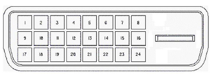
10DVI-D
Pin Signal Pin Signal
1 TMDS Data 2- 13 TMDS 3+
2 TMDS Data 2+ 14 +5V DDC Power
3 TMDS Data 2/4 Shield 15 Gnd (+5, Analog V/H Sync)
4 TMDS 4- 16 Hot Plug Detect
5 TMDS 4+ 17 TMDS Data 0-
6 DDC Clock 18 TMDS Data 0+
7 DDC Data 19 TMDS Data 0/5 Shield
8 No Connection 20 TMDS Data 5-
9 TMDS Data 1- 21 TMDS Data 5+
10 TMDS Data 1+ 22 TMDS Clock Shield
11 TMDS Data 1/3 Shield 23 TMDS Clock+
12 TMDS 3- 24 TMDS Clock-C1
Display Port(1.2a)
Pin Signal Pin Signal
1 ML_Lane 0(p) Data3 + 11 Signal ground
2 Signal ground 12 ML_Lane 3(n) Data0 -
3 ML_Lane 0(n) Data3 - 13 Signal ground
4 ML_Lane 1(p) Data2 + 14 Signal ground
AUX_CH(p) AUX + Signal for
5 Signal ground 15
Auxiliary Channel
6 ML_Lane 1(n) Data2 - 16 Signal ground
AUX_CH(n) AUX - Signal for
7 ML_Lane 2(p) Data1 + 17
Auxiliary Channel
8 Signal ground 18 Hot Plug
119 ML_Lane 2(n) Data 1 - 19 DP_PWR Return
10 ML_Lane 3(p) Data0 + 20 DP_PWR
HDMI(1.3) (compatible with HDMI1.4)
Pin Signal Pin Signal
1 TMDS Data2+ 11 TMDS Clock Shield
2 TMDS Data2 Shield 12 TMDS Clock–
3 TMDS Data2– 13 CEC
4 TMDS Data1+ 14 Reserved (N.C. on device)
5 TMDS Data1 Shield 15 SCL
6 TMDS Data1– 16 SDA
7 TMDS Data0+ 17 DDC/CEC Ground
8 TMDS Data0 Shield 18 +5V Power
9 TMDS Data0– 19 Hot Plug Detect
10 TMDS Clock+
1.5.3 Signal Connector
USB Connector
Pin Signal Pin Signal
1 VCC 3 D+
2 D- 4 GND
12RJ11 Connector (for Remote Key) (option) Pin Signal Pin Signal 1 MENU 4 SELECT 2 UP 5 POWER 3 DOWN 6 GND 13
1.6 Package Overview

     LCD Display           Power Cord         DC Power Supply

                       USB cable or USB C-A
      VGA cable                                  DVI cable
                              cable

     HDMI cable              DP cable

14
! Warning! This product is intended to be supplied by a Listed Power Adapter or DC power source, rated 12Vdc, 2A minimum, Tma = 40 degree C minimum, and the altitude of operation = 3048m minimum. If it needs further assistance with purchasing the power source, please contact to MicroTouch for further information. ! Mise en garde! Cet appareil est conçu avec une alimentation de courant CA, d’une tension nominale de 12Vdc, 2A minimum, Tma = 40 degrés C minimum et l’altitude de l’utilisation = 3048 m minimum. Pour d’autres conseils pour l’installation de la source d’alimentation, communiquer avec MicroTouch pour de plus amples renseignements. 15
Chapter 2
     Product Installation

16
2.1 About VESA Mount
The SK-156P-A1 series conform to the “VESA Flat Display Mounting Interface
Standard” which defines a physical mounting interface for touch monitor, and
corresponding with the standards of touch monitor mounting devices. The VESA
mount is located on the back of this unit.
VESA Mount
! Warning!
Please select the MicroTouch original screws!
The distance between the back cover surface and the bottom of the screw hole
is 8 mm. Please use four M4 screws diameter with 8-10mm proper length to
mount your monitor.
Note: The mounting stand must be able to support at least 5.4 lbs (2.7 Kg).
! Mise en garde!
Sélectionner les vis d’origine de MicroTouch!
La distance entre la surface du couvercle arrière et le bas de l’orifice de la vis
est de 8 mm et 18mm. Utiliser les vis M4 de diamètre pour le montage de
votre moniteur.
Remarque : Le support de montage doit pouvoir supporter un poids d’au moins
5.4 lb (2,7kg).
172.2 On-Screen Display
Old OSD
OSD
Menu off status Menu on status
Key
MENU Menu appear Menu disappear/ return to main item
▲ Brightness Main item select up/ Adjust up
▼ Contrast Main item select down/ Adjust down
SELECT Enter/Select sub-item function
Power On/Off
1. Press the “MENU” button to pop up the “on-screen menu” and press “Up” or
“Down” button to select among the six functions in the main menu.
2. Choose the adjustment items by pressing the “Enter” button.
3. Adjust the value of the adjustment items by pressing the “Up” or “Down” button.
4. With the OSD menu on screen, press “Menu” button to return main menu or exit
OSD.
5. The OSD menu will automatically close, if you have left it idle for a pre-set time.
6. To Lock / Unlock the OSD / Power menu buttons, press “Menu” and “Minus” at
the same time to Select OSD / Power the Lock / Unlock function.
Please note:
18a. When the OSD Lock function is selected, this indicates that all the buttons
except “power” button are now disabled.
b. When the Power Lock function is selected, this indicates that the power key
is disabled; user can not to turn off the monitor by "Power" key.
7. To disable the touch function, press “Menu” and “Enter” Key, at the same time.
8. To enable the touch function, press “Menu” and “Enter” Key, at the same time
for five seconds.
9. Press the power key button, there will be an OSD window pop up to ask if it
should be going off.
If press the power key in five seconds, the monitor power will be off. If don’t
press the power key in five seconds, the OSD window will be gone and return to
the normal status instead.
10. Direct input select function
Press and keep pressing “Select” key for 5 seconds, will change to another one
input source.
Please note:
When choosing VGA, only VGA signal can wake up monitor. When choosing
DVI or HDMI or DP, only DVI or HDMI or DP can wake up the monitor.
11. Factory mode:
In power off status and plug signal cable, press the “Plus” and “Minus” key at the
same time press “Power” key on into factory mode.
12. Burn-in mode:
In power off status and pull out signal cable, press the “Menu” and “Plus” key at
the same time press “Power” key on into Burin-in mode.
13. Work time:
In factory mode, displays monitor the work time counting in hours.
19New OSD
OSD
Menu off status Menu on status
Key
MENU Menu appear Menu disappear/ return to main item
▲ Brightness Main item select up/ Adjust up
▼ Contrast Main item select down/ Adjust down
SELECT Source select Enter/Select sub-item function
Power On/Off
1. Press the “MENU” button to pop up the “on-screen menu” and press “Up” or
“Down” button to select among the four functions in the main menu.
2. Choose the adjustment items by pressing the “SELECT ” button.
3. Adjust the value of the adjustment items by pressing the “Up” or “Down” button.
4. With the OSD menu on screen, press “ Menu” button to return main menu or exit
OSD.
5. The OSD menu will automatically close, if you have left it idle for a pre-set time.
6. To Lock / Unlock the OSD / Power menu buttons, press “Menu” and “Minus” at
the same time to Select OSD / Power the Lock / Unlock function.
Please note:
a. When the OSD Lock function is selected, this indicates that all the buttons
except “power” button are now disabled.
b. When the Power Lock function is selected, this indicates that the power key
is disabled; user can not to turn off the monitor by "Power" key.
7. To disable the touch function, press “Menu” and “Enter” Key, at the same time.
8. To enable the touch function, press “Menu” and “Enter” Key, at the same time for
five seconds.
9. Press the power key button, there will be an OSD window pop up to ask if it
should be going off.
If press the power key in five seconds, the monitor power will be off. If don’t
press the power key in five seconds, the OSD window will be gone and return to
the normal status instead.
10. Direct input select function
Screen display status:
20Press and keep pressing “Select” key for 3 seconds, will change to pop up
“source select” OSD.
Sleep status:
Press and keep pressing “Select” key for 1 seconds, will change to pop up
“source select” OSD.
Please note:
When choosing VGA, only VGA signal can wake up monitor. When choosing
HDMI, only HDMI can wake up the monitor. When choosing DISPLAYPORT,
only DISPLAYPORT can wake up the monitor.
11. Factory mode:
Press the “MENU” button to pop up the “on-screen menu” and select "Option"
icon in "Factory" item, key in password "3","3","3","3" into factory mode.
12. Burn-in mode:
In Factory mode to select “Burn In” item into Burin-in mode (unplug signal cable
or do not enter the signal source).
13. Work time:
In factory mode, displays monitor the work time counting in hours.
212.2.1 OSD Function Description
Item Content Default
Contrast The monitor luminance level control. 50
T1634MC-B8X /
Brightness The monitor backlight level control. TF1634MC-B8X:75
Other:100
Fine-tune the image to full screen
Auto Adjust NA
automatically.
Moving screen image horizontal position
Left/Right NA
to left or right.
Moving screen image vertical position to
Up/Down NA
up or down.
The screen image horizontal dot clock
Horizontal size NA
adjustment.
The screen image pixel phase
Fine NA
adjustment.
Moving OSD menu horizontal position to
OSD Left/Right 50
left or right.
Moving OSD menu vertical position to up
OSD Up/Down 50
or down.
T1634MC-B5X /
OSD Time out OSD auto-disappear time selection. TF1634MC-B6X:5
Other:15
OSD menu language selection.
( English, French, Japanese, Deutsch,
OSD Language English
Spanish, Italian, Traditional Chinese and
Simplified Chinese)
Factory Reset Factory default value restored. NA
Color temperature selection.
RGB USER
(9300K, 6500K, 5500K, 7500K, User)
Select Input function.
(Auto, VGA,DVI)
Input Select Auto
Select Input function.
(Auto, VGA,HDMI,DISAPLAY PORT)
222.2.2 Timing Table Chart
H-Freq. Band Width Polarity
Mode Resolution
(KHz) (MHz) H V
1 640x480 60Hz 31.47 25.175 - -
2 800x600 60Hz 37.88 40 + +
3 1024x768 60Hz 48.36 65 - -
4 1280x1024 60Hz 64 108 + +
5 1280x960 60Hz 60 108 + +
6 1366x768 60Hz 47.7 85.38 + +
7 1440x900 60Hz 56 106.5 - +
8 1680x1050 60Hz 65.2 146 - +
9 1920x1080 60Hz 67.5 148.5 + +
Note:
1. If input H-display > 1920 pixel or V-display > 1080 lines or V-Sync >63Hz, then
OSD shall display warning out of range.
2. The screen does not fit the monitor for 640x480 60Hz.
2.3.3 EDID Data
The monitor assembly shall provide a display communications channel that
conforms to VESA DDC2B hardware requirements. This configuration shall contain
the 128-byte EDID file as specified by VESA EDID Standard.
232.3 Dimension 2.3.1 Front View 2.3.2 Side View 24
2.3.3 Rear View

25
Appendix

26
Declaration of the Presence Condition of the Restricted Substances Marking

設備名稱:觸控螢幕                                         型號(型式):SK-156P-A1
Equipment name:Touch LCD Monitor            Type designation (Type) :SK-156P-A1

                 限用物質及其化學符號
                 Restricted substances and its chemical symbols
單元 Unit                                      六價鉻             多溴聯苯             多溴二苯醚
                 鉛      汞
                                   鎘 Cadmium Hexavalent      Polybrominated   Polybrominated
                 Lead   Mercury
                                   (Cd)      chromium        biphenyls        diphenyl ethers
                 (Pb)   (Hg)
                                             (Cr+6)          (PBB)            (PBDE)
塑膠零件
                   ○        ○           ○            ○              ○                ○
Plastic Parts
金屬零件
                   -        ○           ○            ○              ○                ○
Metal Parts
線纜和電纜組件
Cable              -        ○           ○            ○              ○                ○
component
LCD 面板
                   -        ○           ○            ○              ○                ○
LCD Panel
觸控式螢幕面板
                   -        ○           ○            ○              ○                ○
Touch Panel
PCBA               -        ○           ○            ○              ○                ○
軟體(CD 等)
                   ○        ○           ○            ○              ○                ○
Software

Note 1:〝Exceeding 0.1 wt %〞and〝exceeding 0.01 wt %〞indicate that the percentage content of
the restricted substance exceeds the reference percentage value of presence condition.。

Note 2:〝○〞indicates that the percentage content of the restricted substance does not exceed the
percentage of reference value of presence.

Note 3:The〝−〞indicates that the restricted substance corresponds to the exemption.

27
Vous pouvez aussi lire