Operating instructions Betriebsanleitung Mode d'emploi Manual de instrucciones
←
→
Transcription du contenu de la page
Si votre navigateur ne rend pas la page correctement, lisez s'il vous plaît le contenu de la page ci-dessous
Operating instructions
                                 Betriebsanleitung
                                 Mode d'emploi
                                 Manual de instrucciones

Inductive contact model 831                                     GB
in pressure and temperature gauges
Induktivkontakt Typ 831                                         D
in Druck- und Temperaturmessgeräten
Contact inductif type 831                                       F
des manomètres et thermomètres
Contacto inductivo, modelo 831                                  E
en manómetros o termómetros

     Inductive contact     Inductive contact model 831.1
     Model 831.112         in pressure gauge model 232.50.100
GB Operating instructions model 831                               Page 3 - 24

 D Betriebsanleitung Typ 831                                      Seite 25 - 46

 F Mode d‘emploi type 831                                         Page 47 - 56

 E Manual de instrucciones modelo 831                             Página 57 - 66

   © 2010 WIKA Alexander Wiegand SE & Co. KG
   All rights reserved. / Alle Rechte vorbehalten.
   WIKA® is a registered trademark in various countries.
   WIKA® ist eine geschützte Marke in verschiedenen Ländern.

   Prior to starting any work, read the operating instructions!
   Keep for later use!

   Vor Beginn aller Arbeiten Betriebsanleitung lesen!
   Zum späteren Gebrauch aufbewahren!

   Lire le mode d‘emploi avant de commencer toute opération !
                                                                                             2371673.05 05/2014 GB/D/F/E

   A conserver pour une utilisation ultérieure !

   ¡Leer el manual de instrucciones antes de comenzar cualquier trabajo!
   ¡Guardar el manual para una eventual consulta!

   22                              WIKA operating instructions inductive contact model 831
Contents
Contents
GB
1. General information 4
2. Safety 5
3. Specifications 8
4. Design and function 8
5. Transport, packaging and storage 9
6. Commissioning, operation 10
7. Maintenance and cleaning 12
8. Dismounting and disposal 12
Appendix 1: EC-type examination certificate (Ex approval for
gases) for slot sensors models SJ
(WIKA model 831) 13 - 15
Appendix 2: EC-type examination certificate (Ex approval for
gases) for SN sensors models SJ
(WIKA model 831-SN/S1N) 16 - 19
Appendix 3: EC-type examination certificate (Ex approval
for dusts) for proximity sensors models SJ
(WIKA model 831 and 831-SN/S1N) 20 - 24
2371673.05 05/2014 GB/D/F/E
WIKA operating instructions inductive contact model 831 31. General information
1. General information
■■ The inductive contacts described in the operating instructions have been
designed and manufactured using state-of-the-art technology.
GB All components are subject to stringent quality and environmental criteria
during production. Our management systems are certified to ISO 9001 and
ISO 14001.
■■ These operating instructions contain important information on handling the
inductive contacts. Working safely requires that all safety instructions and work
instructions are observed.
■■ Observe the relevant local accident prevention regulations and general safety
regulations for the inductive contacts' range of use.
■■ The operating instructions are part of the product and must be kept in the im-
mediate vicinity of the instruments with inductive contacts and readily acces-
sible to qualified personnel at any time.
■■ Skilled personnel must have carefully read and understood the operating
instructions, prior to beginning any work.
■■ The manufacturer's liability is void in the case of any damage caused by
using the product contrary to its intended use, non-compliance with these
operating instructions, assignment of insufficiently qualified skilled personnel
or unauthorised modifications to the inductive contact.
■■ The general terms and conditions, contained in the sales documentation, shall
apply.
■■ Subject to technical modifications.
■■ Further information:
- Internet address: www.wika.de / www.wika.com
- Relevant data sheet: AC 08.01
2371673.05 05/2014 GB/D/F/E
4 WIKA operating instructions inductive contact model 8311. General information / 2. Safety
Explanation of symbols
WARNING!
... indicates a potentially dangerous situation that can result in
serious injury or death, if not avoided. GB
Information
… points out useful tips, recommendations and information for
efficient and trouble-free operation.
WARNING!
... indicates a potentially dangerous situation in a potentially
explosive atmosphere, resulting in serious injury or death, if not
avoided.
2. Safety
WARNING!
Before installation, commissioning and operation, ensure that
the appropriate inductive contact has been selected in terms of
design and specific measuring conditions.
Non-observance can result in serious injury and/or damage to
equipment.
Only work on the instrument with the voltage disconnected.
Further important safety instructions can be found in the indi-
vidual chapters of these operating instructions.
2.1 Intended use
Inductive contacts are installed in pressure and temperature measuring
instruments. The instrument pointer of the measuring instrument moves the flag
of the inductive contact out of or into the slot sensor. The resulting change of the
current supply is used for triggering a switching amplifier.
The inductive contact has been designed and built solely for the intended use
described here and may only be used accordingly.
2371673.05 05/2014 GB/D/F/E
The manufacturer shall not be liable for claims of any type based on operation
contrary to the intended use.
WIKA operating instructions inductive contact model 831 52. Safety
2.2 Personnel qualification
WARNING!
Risk of injury should qualification be insufficient!
GB Improper handling can result in considerable injury and damage
to equipment.
■■ The activities described in these operating instructions may
only be carried out by skilled personnel who have the qualifica-
tions described below.
Skilled personnel
Skilled personnel are understood to be personnel who, based on their technical
training, knowledge of measurement and control technology and on their experi-
ence and knowledge of country-specific regulations, current standards and direc-
tives, are capable of carrying out the work described and independently recognis-
ing potential hazards.
2.3 Additional safety instructions for instruments per ATEX
WARNING!
Non-observance of these instructions and their contents may
result in the loss of explosion protection.
WARNING!
It is imperative that the application conditions and safety require-
ments of the EC-type examination certificate are followed.
Pressure gauges must be earthed via the process connection!
2.4 Special hazards
WARNING!
Observe the information given in the applicable type examination
certificate and the relevant country-specific regulations for
installation and use in potentially explosive atmospheres (e.g.
IEC 60079-14, NEC, CEC). Non-observance can result in serious
injury and/or damage to equipment.
Dangerous pressure media such as oxygen, acetylene, flammable gases or
liquids, toxic gases or liquids as well as for refrigeration plants or compressors
require attention above the standard regulations. Here the specific safety codes or
regulations must be considered.
2371673.05 05/2014 GB/D/F/E
For additional important safety instructions see chapter "2.3 Safety instructions for
instruments per ATEX".
WARNING!
Residual media in dismounted measuring instruments can
result in a risk to persons, the environment and equipment. Take
sufficient precautionary measures.
6 WIKA operating instructions inductive contact model 8312. Safety
2.5 Labelling / safety marks
Product label
GB
Pin assignment Date of manufacture
Explanation of symbols
Before mounting and commissioning the pressure gauge,
ensure you read the operating instructions!
CE, Communauté Européenne
Instruments bearing this mark comply with the relevant European
directives.
ATEX European Explosion Protection Directive
(Atmosphère = AT, explosible = Ex)
Instruments bearing this mark comply with the requirements of
the European Directive 94/9/EC (ATEX) on explosion protection.
2371673.05 05/2014 GB/D/F/E
WIKA operating instructions inductive contact model 831 73. Specifications / 4. Design and function
3. Specifications
IP Ingress protection
GB The ingress protection to EN 60529 against external influences depends on the
basic instrument and is found in the respective data sheet.
Admissible ambient temperatures
The inductive contacts can be used in the range from -25 to +70 °C (SN sensors
up to +100 °C). Where the permissible temperatures for the basic instrument (see
data sheet) deviate from this range, the lower value is valid.
When operating in potentially explosive atmospheres, please note the reduced
values (see respective EC-type examination certificate).
For the type of the integrated slot sensors, see the measuring instrument's
product label.
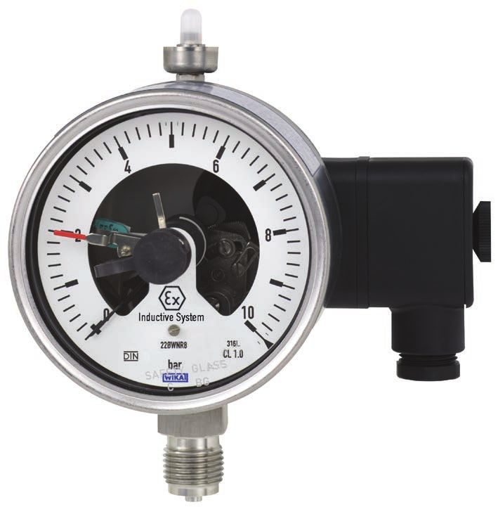
4. Design and function
Description
The built-in electrical switch contacts are non-contact slot-type inductive proximity
sensors, which are powered from switching amplifiers with certified intrinsically
safe circuits. When the adjustable set points are reached, their output circuits will
be opened or closed.
■■ As standard model 831 slot sensors, to EC-type examination certificate
PTB 99 ATEX 2219 X (see appendix 1) and ZELM 03 ATEX 0128 X (see
appendix 3), are used
■■ Model 831-SN and -S1N SN sensors, to PTB 00 ATEX 2049 X (see appendix
2) and ZELM 03 ATEX 0128 X (see appendix 3), are special designs with
safety features (that are not relevant to explosion protection) for special
applications
The connected loads for the switches are in accordance with EN 60947-5-6
(NAMUR).
Suitable switching amplifiers for model 831 are:
With type 1 circuit: Control unit KFD2-SR2-Ex1 and
KFD2-SR2-Ex2
2371673.05 05/2014 GB/D/F/E
With type 2 circuit: Control unit KFA6-SR2-Ex1 and
KFA6-SR2-Ex2 - model 904.28/29
Suitable switching amplifiers for model 831-SN and 831-S1N are:
With type 2 circuit: Control unit KFD2-SH-Ex1 and
KHA6-SH-Ex1 - model 904.30
8 WIKA operating instructions inductive contact model 8314. Design and function / 5. Transport, packaging ...
Scope of delivery
Cross-check scope of delivery with delivery note.
GB
5. Transport, packaging and storage
5.1 Transport
Check pressure gauge for any damage that may have been caused by transport.
Obvious damage must be reported immediately.
5.2 Packaging
Do not remove packaging until just before mounting.
Keep the packaging as it will provide optimum protection during transport (e.g.
change in installation site, sending for repair).
5.3 Storage
Permissible conditions at the place of storage:
Storage temperature: -20 ... +70 °C
2371673.05 05/2014 GB/D/F/E
WIKA operating instructions inductive contact model 831 96. Commissioning, operation
6. Commissioning, operation
Mechanical connection
GB ■■ In accordance with the general technical regulations for pressure and
temperature measuring instruments (e.g. EN 837-2 or EN 13190).
When screwing gauges in, the force required for this must not be applied through
the case, but rather through the spanner flats (using a suitable tool) provided for
this purpose on the square shaft of standard connections.
Installation with
spanner
With safety pattern gauges (see dial symbol k) you need to pay attention to the
fact that the free space behind the blow-out back will be at least 15 mm.
Requirements for the installation point
To avoid, amongst other things, switch signal "chatter", it must be ensured that the
instruments are mounted free of vibration.
If the measuring point is not sufficiently stable a measuring instrument support
such as a bracket or flange should be used for fastening (possibly via a flexible
capillary). If the pressure gauge is exposed to vibration or pulsating pressure
or both, then a liquid filled pressure gauge may provide considerably better
performance and readability. Instruments should be protected against coarse dirt
and wide fluctuations in ambient temperature.
Electrical connection
■■ Connection of the switches via screw terminals in the terminal box
■■ Conductor cross section max. 1.5 mm2
■■ The terminal assignment is stated on the product label of the pressure or tem-
perature measuring instrument
■■ The gauges must be connected to the equipotential bonding of the plant
2371673.05 05/2014 GB/D/F/E
10 WIKA operating instructions inductive contact model 8316. Commissioning, operation
The permissible limits of Ui, Ii and Pi for the intrinsically safe supply circuits
depend on the sensor type. They can be taken from the corresponding EC-type
examination certificates. (The sensor type is stated on the connection label of
the pressure or temperature measuring instrument.)
GB
Suitable switching amplifiers are e.g.:
Circuit Sensor type Model designation EC-type examination WIKA
(s. Ex certificate) Fa. Pepperl & Fuchs certificate Model
Model 1 standard KFD2-SR2-Ex1 PTB 00 ATEX 2080 904.31
standard KFD2-SR2 Ex2 PTB 00 ATEX 2080 904.32
Model 2 standard KFA6-SR2-Ex1 PTB 00 ATEX 2081 904.28
standard KFA6-SR2-Ex2 PTB 00 ATEX 2081 904.29
SN-sensors KFD2-SH-Ex1 PTB 00 ATEX 2042 904.33
SN-sensors KHA6-SH-Ex1 PTB 00 ATEX 2043 904.30
Electromagnetic compatibility
EMC to EN 60947-5-2.
The instruments are to be protected against strong electromagnetic fields.
Adjusting the set pointers
The setting of the set points is achieved using the adjustment lock in the win-
dow with the aid of the adjustment key (part of the scope of delivery; found in
standard instruments on the side of the terminal box).
Set pointer
removable
adjustment key
Adjustment lock
2371673.05 05/2014 GB/D/F/E
The set pointers for the limit switches are freely adjustable over the full scale
range. For reasons of switching accuracy and long life of the mechanical
measuring systems, the switch points should be between 10 % and 90 % of the
measuring span.
WIKA operating instructions inductive contact model 831 117. Maintenance and cleaning / 8. Dismounting and disposal
7. Maintenance and cleaning
7.1 Maintenance
The instruments are maintenance-free.
GB
The indicator and switching function should be checked once or twice every
year. The instrument must be disconnected from the process to check with a
pressure or temperature testing device.
Repairs must only be carried out by the manufacturer or appropriately qualified
skilled personnel.
7.2 Cleaning
CAUTION!
■■ Before cleaning, correctly disconnect the measuring
instrument from the pressure supply, switch it off and
disconnect it from the mains.
■■ Clean the instrument with a moist cloth.
■■ Electrical connections must not come into contact with
moisture.
■■ It must be ensured that all the parts are dry before the power
is switched on again.
■■ Wash or clean the dismounted measuring instrument before
returning it, in order to protect personnel and the environment
from exposure to residual media.
8. Dismounting and disposal
WARNING!
Residual media in dismounted measuring instruments can result
in a risk to persons, the environment and equipment.
Take sufficient precautionary measures.
8.1 Dismounting
2371673.05 05/2014 GB/D/F/E
Only disconnect the measuring instrument once the system has been
depressurised!
8.2 Disposal
Incorrect disposal can put the environment at risk. Dispose of instrument
components and packaging materials in an environmentally compatible way and
in accordance with the country-specific waste disposal regulations.
12 WIKA operating instructions inductive contact model 831Appendix 1:
GB
2371673.05 05/2014 GB/D/F/E
WIKA operating instructions inductive contact model 831 13Appendix 1:
GB
2371673.05 05/2014 GB/D/F/E
14 WIKA operating instructions inductive contact model 831Appendix 1:
GB
2371673.05 05/2014 GB/D/F/E
WIKA operating instructions inductive contact model 831 15Appendix 2:
GB
2371673.05 05/2014 GB/D/F/E
16 WIKA operating instructions inductive contact model 831Appendix 2:
GB
2371673.05 05/2014 GB/D/F/E
WIKA operating instructions inductive contact model 831 17Appendix 2:
GB
2371673.05 05/2014 GB/D/F/E
18 WIKA operating instructions inductive contact model 831Appendix 2:
GB
2371673.05 05/2014 GB/D/F/E
WIKA operating instructions inductive contact model 831 19Appendix 3:
GB
2371673.05 05/2014 GB/D/F/E
20 WIKA operating instructions inductive contact model 831Appendix 3:
GB
2371673.05 05/2014 GB/D/F/E
WIKA operating instructions inductive contact model 831 21Appendix 3:
GB
2371673.05 05/2014 GB/D/F/E
22 WIKA operating instructions inductive contact model 831Appendix 3:
GB
2371673.05 05/2014 GB/D/F/E
WIKA operating instructions inductive contact model 831 23Appendix 3:
GB
2371673.05 05/2014 GB/D/F/E
24 WIKA operating instructions inductive contact model 831Inhalt
Inhalt
1. Allgemeines 26
D
2. Sicherheit 27
3. Technische Daten 30
4. Aufbau und Funktion 30
5. Transport, Verpackung und Lagerung 31
6. Inbetriebnahme, Betrieb 32
7. Wartung und Reinigung 34
8. Demontage und Entsorgung 34
Anlage 1: EG-Baumusterprüfbescheinigung (Ex-Zulassung
für Gase) für Schlitzinitiatoren Typen SJ
(WIKA-Typ 831) 35 - 37
Anlage 2: EG-Baumusterprüfbescheinigung (Ex-Zulassung
für Gase) für SN-Sensoren Typen SJ
(WIKA-Typ 831-SN/S1N) 38 - 41
Anlage 3: EG-Baumusterprüfbescheinigung (Ex-Zulassung
für Stäube) für Näherungssensoren Typen SJ
(WIKA-Typ 831 und 831-SN/S1N) 42 - 46
2371673.05 05/2014 GB/D/F/E
WIKA Betriebsanleitung Induktivkontakt Typ 831 251. Allgemeines
1. Allgemeines
■■ Die in der Betriebsanleitung beschriebenen Induktivkontakte werden nach dem
aktuellen Stand der Technik konstruiert und gefertigt.
Alle Komponenten unterliegen während der Fertigung strengen Qualitäts-
und Umweltkriterien. Unsere Managementsysteme sind nach ISO 9001 und
ISO 14001 zertifiziert.
D
■■ Diese Betriebsanleitung gibt wichtige Hinweise zum Umgang mit den Induktiv-
kontakten. Voraussetzung für sicheres Arbeiten ist die Einhaltung aller angege-
benen Sicherheitshinweise und Handlungsanweisungen.
■■ Die für den Einsatzbereich der Induktivkontakte geltenden örtlichen Unfallver-
hütungsvorschriften und allgemeinen Sicherheitsbestimmungen einhalten.
■■ Die Betriebsanleitung ist Produktbestandteil und muss in unmittelbarer Nähe
des Gerätes mit Induktivkontakten für das Fachpersonal jederzeit zugänglich
aufbewahrt werden.
■■ Das Fachpersonal muss die Betriebsanleitung vor Beginn aller Arbeiten sorg-
fältig durchgelesen und verstanden haben.
■■ Die Haftung des Herstellers erlischt bei Schäden durch bestimmungswidrige
Verwendung, Nichtbeachten dieser Betriebsanleitung, Einsatz ungenügend
qualifizierten Fachpersonals sowie eigenmächtiger Veränderung am Induktiv-
kontakt.
■■ Es gelten die allgemeinen Geschäftsbedingungen in den Verkaufsunterlagen.
■■ Technische Änderungen vorbehalten.
■■ Weitere Informationen:
- Internet-Adresse: www.wika.de / www.wika.com
- zugehöriges Datenblatt: AC 08.01 2371673.05 05/2014 GB/D/F/E
26 WIKA Betriebsanleitung Induktivkontakt Typ 8311. Allgemeines / 2. Sicherheit
Symbolerklärung
WARNUNG!
… weist auf eine möglicherweise gefährliche Situation hin, die
zum Tod oder zu schweren Verletzungen führen kann, wenn sie
nicht gemieden wird.
Information D
… hebt nützliche Tipps und Empfehlungen sowie Informationen
für einen effizienten und störungsfreien Betrieb hervor.
WARNUNG!
… weist auf eine möglicherweise gefährliche Situation im
explosionsgefährdeten Bereich hin, die zum Tod oder zu
schweren Verletzungen führt, wenn sie nicht gemieden wird.
2. Sicherheit
WARNUNG!
Vor Montage, Inbetriebnahme und Betrieb sicherstellen, dass
der richtige Induktivkontakt hinsichtlich Ausführung und spezi-
fischen Messbedingungen ausgewählt wurde.
Bei Nichtbeachten können schwere Körperverletzungen und/
oder Sachschäden auftreten.
Alle Arbeiten dürfen nur im spannungslosen Zustand erfolgen.
Weitere wichtige Sicherheitshinweise befinden sich in den ein-
zelnen Kapiteln dieser Betriebsanleitung.
2.1 Bestimmungsgemäße Verwendung
Induktivkontakte werden in Druck- und Temperaturmessgeräte eingebaut. Der In-
strumentenzeiger des Messgerätes bewegt die Steuerfahne des Induktivkontaktes
aus- oder in den Schlitzinitiator. Die daraus resultierende Änderung der Stromauf-
nahme wird zur Ansteuerung eines Schaltverstärkers genutzt.
Der Induktivkontakt ist ausschließlich für den hier beschriebenen bestimmungsge-
2371673.05 05/2014 GB/D/F/E
mäßen Verwendungszweck konzipiert und konstruiert und darf nur dementspre-
chend verwendet werden.
Ansprüche jeglicher Art aufgrund von nicht bestimmungsgemäßer Verwendung
sind ausgeschlossen.
WIKA Betriebsanleitung Induktivkontakt Typ 831 272. Sicherheit
2.2 Personalqualifikation
WARNUNG!
Verletzungsgefahr bei unzureichender Qualifikation!
Unsachgemäßer Umgang kann zu erheblichen Personen- und
Sachschäden führen.
■■ Die in dieser Betriebsanleitung beschriebenen Tätigkeiten nur
D durch Fachpersonal nachfolgend beschriebener Qualifikation
durchführen lassen.
Fachpersonal
Das Fachpersonal ist aufgrund seiner fachlichen Ausbildung, seiner Kenntnisse
der Mess- und Regelungstechnik und seiner Erfahrungen sowie Kenntnis der
landesspezifischen Vorschriften, geltenden Normen und Richtlinien in der Lage,
die beschriebenen Arbeiten auszuführen und mögliche Gefahren selbstständig zu
erkennen.
2.3 Zusätzliche Sicherheitshinweise für Geräte nach ATEX
WARNUNG!
Die Nichtbeachtung dieser Inhalte und Anweisungen kann zum
Verlust des Explosionsschutzes führen.
WARNUNG!
Einsatzbedingungen und sicherheitstechnische Daten der
EG Baumusterprüfbescheinigung unbedingt beachten.
Messgeräte über den Prozessanschluss erden!
2.4 Besondere Gefahren
WARNUNG!
Die Angaben der geltenden Baumusterprüfbescheinigung sowie
die jeweiligen landesspezifischen Vorschriften zur Installation und
Einsatz in explosionsgefährdeten Bereichen (z. B. IEC 60079-14,
NEC, CEC) einhalten. Bei Nichtbeachten können schwere Kör-
perverletzungen und/oder Sachschäden auftreten.
Bei gefährlichen Messstoffen wie z. B. Sauerstoff, Acetylen, brennbaren oder
giftigen Stoffen, sowie bei Kälteanlagen, Kompressoren etc. müssen über die
gesamten allgemeinen Regeln hinaus die jeweils bestehenden einschlägigen
Vorschriften beachtet werden.
2371673.05 05/2014 GB/D/F/E
Weitere wichtige Sicherheitshinweise siehe Kapitel "2.3 Sicherheitshinweise für
Geräte nach ATEX".
WARNUNG!
Messstoffreste in ausgebauten Messgeräten können zur
Gefährdung von Personen, Umwelt und Einrichtung führen.
Ausreichende Vorsichtsmaßnahmen ergreifen.
28 WIKA Betriebsanleitung Induktivkontakt Typ 8312. Sicherheit
2.5 Beschilderung / Sicherheitskennzeichnungen
Typenschild
D
Anschlussbelegung Herstellungsdatum
Symbolerklärung
Vor Montage und Inbetriebnahme des Druckmessgerätes
unbedingt die Betriebsanleitung lesen!
CE, Communauté Européenne
Geräte mit dieser Kennzeichnung stimmen überein mit den zu-
treffenden europäischen Richtlinien.
ATEX Europäische Explosionsschutz-Richtlinie
(Atmosphère = AT, explosible = Ex)
Geräte mit dieser Kennzeichnung stimmen überein mit den
Anforderungen der europäischen Richtlinie 94/9/EG (ATEX) zum
Explosionsschutz.
2371673.05 05/2014 GB/D/F/E
WIKA Betriebsanleitung Induktivkontakt Typ 831 293. Technische Daten / 4. Aufbau und Funktion
3. Technische Daten
IP-Schutzart
Die Schutzart nach EN 60529 gegen äußere Einflüsse hängt vom Grundgerät ab
und ist dem entsprechenden Datenblatt zu entnehmen.
D Zulässige Umgebungstemperaturen
Die Induktivkontakte können im Bereich von -25 bis +70 °C (SN-Initiatoren
bis +100 °C) eingesetzt werden. Falls die für das Grundgerät zugelassenen
Temperaturen (siehe Datenblatt) diesen Bereich eingrenzen, gelten die
eingeschränkten Werte.
Bei Einsatz im explosionsgefährdeten Bereich sind reduzierte Werte zu beachten
(siehe jeweilige EG-Baumusterprüfbescheinigung).
Typ der jeweils eingebauten Schlitzinitiatoren siehe Typenschild des Messge-
rätes.
4. Aufbau und Funktion
Beschreibung
Die eingebauten elektrischen Schaltkontakte sind berührungslos arbeitende,
induktive Näherungsschalter in Schlitzbauform, die aus Trennschaltverstärkern mit
bescheinigten eigensicheren Stromkreisen versorgt werden. Bei Überschreiten
der einstellbaren Grenzwerte werden deren Ausgangsstromkreise geöffnet bzw.
geschlossen.
■■ Standard sind die Schlitzinitiatoren Typ 831 entsprechend der
EG-Baumusterprüfbescheinigung PTB 99 ATEX 2219 X (siehe Anlage 1)
und ZELM 03 ATEX 0128 X (siehe Anlage 3)
■■ Die SN-Sensoren Typ 831-SN bzw. -S1N nach PTB 00 ATEX 2049 X (siehe
Anlage 2) und ZELM 03 ATEX 0128 X (siehe Anlage 3) sind eine Sonderaus-
führung mit (nicht den Explosionsschutz betreffenden) Sicherheitsmerkmalen
für spezielle Anwendungen
Die Anschlusswerte der Schalter entsprechen der EN 60947-5-6 ("NAMUR").
Geeignete Schaltverstärker sind für Typ 831:
Bei Stromkreis Typ 1: Steuergerät KFD2-SR2-Ex1 und
2371673.05 05/2014 GB/D/F/E
KFD2-SR2-Ex2
Bei Stromkreis Typ 2: Steuergerät KFA6-SR2-Ex1 und
KFA6-SR2-Ex2 - Typ 904.28/29
Geeignete Schaltverstärker sind für Typ 831-SN und 831-S1N:
Bei Stromkreis Typ 2: Steuergerät KFD2-SH-Ex1 und
KHA6-SH-Ex1 - Typ 904.30
30 WIKA Betriebsanleitung Induktivkontakt Typ 8314. Aufbau und Funktion / 5. Transport, Verpackung ...
Lieferumfang
Lieferumfang mit dem Lieferschein abgleichen.
5. Transport, Verpackung und Lagerung
5.1 Transport D
Druckmessgerät auf eventuell vorhandene Transportschäden untersuchen.
Offensichtliche Schäden unverzüglich mitteilen.
5.2 Verpackung
Verpackung erst unmittelbar vor der Montage entfernen.
Die Verpackung aufbewahren, denn diese bietet bei einem Transport einen
optimalen Schutz (z. B. wechselnder Einbauort, Reparatursendung).
5.3 Lagerung
Zulässige Bedingungen am Lagerort
Lagertemperatur: -20 ... +70 °C
2371673.05 05/2014 GB/D/F/E
WIKA Betriebsanleitung Induktivkontakt Typ 831 316. Inbetriebnahme, Betrieb
6. Inbetriebnahme, Betrieb
Mechanischer Anschluss
■■ Entsprechend den allgemeinen technischen Regeln für Druck- bzw.
Temperaturmessgeräte (z. B. EN 837-2 bzw. EN 13190).
D Beim Einschrauben der Geräte darf die zum Abdichten erforderliche Kraft nicht
über das Gehäuse oder die Kabelanschlussdose aufgebracht werden, sondern
mit geeignetem Werkzeug nur über die dafür vorgesehenen Schlüsselflächen am
Vierkant des Anschlusszapfens.
Montage mit
Gabelschlüssel
Bei Sicherheitsdruckmessgeräten (zu erkennen am k) ist darauf zu achten, dass
der Freiraum hinter der ausblasbaren Rückwand mindestens 15 mm beträgt.
Anforderungen an die Einbaustelle
Um u.a. ein "Flattern" des Schaltsignals zu vermeiden, ist dafür zu sorgen, dass
die Geräte erschütterungsfrei montiert sind.
Ist die Leitung zum Messgerät für eine erschütterungsfreie Anbringung nicht
stabil genug, sollte (evtl. über eine flexible Kapillarleitung) die Befestigung mittels
Messgerätehalterung erfolgen. Können Erschütterungen nicht durch geeignete
Installationen vermieden werden, dann sollten Geräte mit Flüssigkeitsfüllung
eingesetzt werden. Die Geräte sind vor grober Verschmutzung und starken
Schwankungen der Umgebungstemperatur zu schützen.
Elektrischer Anschluss
■■ Anschluss der Schalter über Schraubklemmen in der Kabeldose
■■ Leitungsquerschnitt max. 1,5 mm2
■■ Klemmenbelegung auf Anschlussschild am Druck- oder Temperaturmessgerät
■■ Die Geräte sind in den Potenzialausgleich der Anlage mit einzubeziehen
2371673.05 05/2014 GB/D/F/E
32 WIKA Betriebsanleitung Induktivkontakt Typ 8316. Inbetriebnahme, Betrieb
Die zulässigen Grenzwerte für Ui, Ii und Pi der eigensicheren Versorgungsstrom-
kreise hängen vom Initiatortyp ab. Sie sind aus den jeweiligen EG-Baumuster-
prüfbescheinigungen zu entnehmen. (Der Initiatortyp ist auf dem Anschluss-
schild des Druck- oder Temperaturmessgerätes angegeben.)
Geeignete Trennschaltverstärker sind z. B.:
Stromkreis Sensortyp Typenbezeichnung EG-Baumuster- WIKA- D
(s. Ex-Schein) Fa. Pepperl & Fuchs prüfbescheinigung Typ
Typ 1 Standard KFD2-SR2-Ex1 PTB 00 ATEX 2080 904.31
Standard KFD2-SR2 Ex2 PTB 00 ATEX 2080 904.32
Typ 2 Standard KFA6-SR2-Ex1 PTB 00 ATEX 2081 904.28
Standard KFA6-SR2-Ex2 PTB 00 ATEX 2081 904.29
SN-Sensoren KFD2-SH-Ex1 PTB 00 ATEX 2042 904.33
SN-Sensoren KHA6-SH-Ex1 PTB 00 ATEX 2043 904.30
Elektromagnetische Verträglichkeit
EMV gemäß EN 60947-5-2.
Die Geräte sind vor starken elektromagnetischen Feldern zu schützen.
Einstellen der Sollwertzeiger
Das Einstellen der Sollwerte erfolgt über das Verstellschloss in der Sichtscheibe
mit Hilfe des Verstellschlüssels (gehört zum Lieferumfang; befindet sich bei
Standardgeräten seitlich an der Kabeldose).
Sollwertzeiger
abnehmbarer
Verstellschlüssel
Verstellschloss
2371673.05 05/2014 GB/D/F/E
Die Sollwertzeiger der Grenzwertschalter sind im gesamten Skalenbereich
frei einstellbar. Aus Gründen der Schaltgenauigkeit und der Lebensdauer der
mechanischen Messsysteme sollen die Schaltpunkte zwischen 10 % und 90 %
der Messspanne liegen.
WIKA Betriebsanleitung Induktivkontakt Typ 831 337. Wartung und Reinigung / 8. Demontage und Entsorgung
7. Wartung und Reinigung
7.1 Wartung
Die Geräte sind wartungsfrei.
Eine Überprüfung der Anzeige und der Schaltfunktion sollte etwa 1 bis 2 mal pro
Jahr erfolgen. Dazu ist das Gerät vom Prozess zu trennen und mit einer Druck-
D oder Temperaturprüfvorrichtung zu kontrollieren.
Reparaturen sind ausschließlich vom Hersteller oder entsprechend qualifizier-
tem Fachpersonal durchzuführen.
7.2 Reinigung
VORSICHT!
■■ Vor der Reinigung das Messgerät ordnungsgemäß von der
Druckversorgung trennen, ausschalten und vom Netz trennen.
■■ Messgerät mit einem feuchten Tuch reinigen.
■■ Elektrische Anschlüsse nicht mit Feuchtigkeit in Berührung
bringen.
■■ Vor Wiedereinschalten des Stromes ist sicherzustellen, dass
alle Teile abgetrocknet sind.
■■ Ausgebautes Messgerät vor der Rücksendung spülen bzw.
säubern, um Mitarbeiter und Umwelt vor Gefährdung durch
anhaftende Messstoffreste zu schützen.
8. Demontage und Entsorgung
WARNUNG!
Messstoffreste in ausgebauten Messgeräten können zur
Gefährdung von Personen, Umwelt und Einrichtung führen.
Ausreichende Vorsichtsmaßnahmen ergreifen.
8.1 Demontage
Messgerät nur im drucklosen Zustand demontieren!
2371673.05 05/2014 GB/D/F/E
8.2 Entsorgung
Durch falsche Entsorgung können Gefahren für die Umwelt entstehen.
Gerätekomponenten und Verpackungsmaterialien entsprechend den
landesspezifischen Abfallbehandlungs- und Entsorgungsvorschriften
umweltgerecht entsorgen.
34 WIKA Betriebsanleitung Induktivkontakt Typ 831Anlage 1:
D
2371673.05 05/2014 GB/D/F/E
WIKA Betriebsanleitung Induktivkontakt Typ 831 35Anlage 1:
D
2371673.05 05/2014 GB/D/F/E
36 WIKA Betriebsanleitung Induktivkontakt Typ 831Anlage 1:
D
2371673.05 05/2014 GB/D/F/E
WIKA Betriebsanleitung Induktivkontakt Typ 831 37Anlage 2:
D
2371673.05 05/2014 GB/D/F/E
38 WIKA Betriebsanleitung Induktivkontakt Typ 831Anlage 2:
D
2371673.05 05/2014 GB/D/F/E
WIKA Betriebsanleitung Induktivkontakt Typ 831 39Anlage 2:
D
2371673.05 05/2014 GB/D/F/E
40 WIKA Betriebsanleitung Induktivkontakt Typ 831Anlage 2:
D
2371673.05 05/2014 GB/D/F/E
WIKA Betriebsanleitung Induktivkontakt Typ 831 41Anlage 3:
D
2371673.05 05/2014 GB/D/F/E
42 WIKA Betriebsanleitung Induktivkontakt Typ 831Anlage 3:
D
2371673.05 05/2014 GB/D/F/E
WIKA Betriebsanleitung Induktivkontakt Typ 831 43Anlage 3:
D
2371673.05 05/2014 GB/D/F/E
44 WIKA Betriebsanleitung Induktivkontakt Typ 831Anlage 3:
D
2371673.05 05/2014 GB/D/F/E
WIKA Betriebsanleitung Induktivkontakt Typ 831 45Anlage 3:
D
2371673.05 05/2014 GB/D/F/E
46 WIKA Betriebsanleitung Induktivkontakt Typ 831Sommaire
Sommaire
Sommaire
1. Généralités 48
2. Sécurité 49
3. Caractéristiques techniques 52 F
4. Conception et fonction 52
5. Transport, emballage et stockage 53
6. Mise en service, utilisation 54
7. Entretien et nettoyage 56
8. Démontage et mise au rebut 56
Annexe 1 : Attestation d’examen de type CE (homologation Ex
pour gaz) pour détecteurs de proximité à fente des types SJ
(type WIKA 831) 35 - 37
Annexe 2 : Attestation d’examen de type CE (homologation Ex
pour gaz) pour détecteurs SN des types SJ
(WIKA type 831-SN/S1N) 38 - 41
Annexe 3 : Attestation d'examen de type CE (homologation Ex
pour poussières) pour détecteurs de proximité à fente des types
SJ (type WIKA 831 et 831-SN/S1N) 42 - 46
2371673.05 05/2014 GB/D/F/E
WIKA mode d'emploi contact inductif type 831 471. Généralités
1. Généralités
■■ Les contacts inductifs décrits dans le présent mode d’emploi sont conçus et
fabriqués selon les dernières technologies en vigueur et tous les composants
sont soumis à des critères de qualité et d’environnement stricts durant la
fabrication. Nos systèmes de gestion sont certifiés selon ISO 9001 et ISO
14001.
■■ Ce mode d'emploi donne des indications importantes concernant l'utilisation
des contacts inductifs. Il est possible de travailler en toute sécurité avec ce
F produit en respectant toutes les consignes de sécurité et d'utilisation.
■■ Respecter les prescriptions locales de prévention contre les accidents et les
prescriptions générales de sécurité en vigueur pour le domaine d'application
des contacts inductifs.
■■ Le mode d'emploi fait partie du produit et doit être conservé à proximité
immédiate des instruments avec contacts inductifs et accessible à tout moment
au personnel qualifié.
■■ Le personnel qualifié doit, avant de commencer toute opération, avoir lu
soigneusement et compris le mode d’emploi.
■■ La responsabilité du fabricant n'est pas engagée en cas de dommages
provoqués par une utilisation non conforme à l'usage prévu, de non respect
de ce mode d'emploi, d'utilisation de personnel trop peu qualifié de même
qu'en cas de modifications du contact inductif effectuées du propre chef de
l'utilisateur.
■■ Les conditions générales de vente mentionnées dans les documents de vente
s'appliquent.
■■ Sous réserve de modifications techniques.
■■ Pour obtenir d'autres informations:
- Consulter notre site internet: www.wika.de / www.wika.com
- Fiche technique correspondante : AC 08.01
2371673.05 05/2014 GB/D/F/E
48 WIKA mode d'emploi contact inductif type 8311. Généralités / 2. Sécurité
Explication des symboles
AVERTISSEMENT !
… indique une situation présentant des risques susceptibles
de provoquer la mort ou des blessures graves si elle n'est pas
évitée.
Information
… met en exergue les conseils et recommandations utiles de
même que les informations permettant d'assurer un fonctionne-
ment efficace et normal. F
AVERTISSEMENT !
… indique une situation en zone explosive présentant des
risques susceptibles de provoquer la mort ou des blessures
graves si elle n'est pas évitée.
2. Sécurité
AVERTISSEMENT !
Avant le montage, la mise en service et le fonctionnement,
s'assurer que le contact inductif a été choisi de façon adéquate,
en ce qui concerne la version et les conditions de mesure
spécifiques.
Un non respect de cette consigne peut entraîner des blessures
corporelles graves et/ou des dégâts matériels.
Toutes les interventions doivent être effectuées hors tension.
Vous trouverez d'autres consignes de sécurité dans les sections
individuelles du présent mode d'emploi.
2.1 Utilisation conforme à l'usage prévu
Les contacts inductifs sont conçus pour l'intégration dans des manomètres et
thermomètres. L'aiguille de l'instrument de mesure connecte ou déconnecte la
broche d'entraînement du contact inductif avec le détecteur de proximité à fente.
La modification de l'alimentation en courant qui en résulte est utilisée pour le
2371673.05 05/2014 GB/D/F/E
pilotage d'un relais amplificateur.
Le contact inductif est conçu et construit exclusivement pour une utilisation
conforme à l'usage prévu décrit ici et ne doit être utilisé qu'en conséquence.
Aucune réclamation ne peut être recevable en cas d‘utilisation non conforme à
l‘usage prévu.
WIKA mode d'emploi contact inductif type 831 492. Sécurité
2.2 Qualification du personnel
AVERTISSEMENT !
Danger de blessure en cas de qualification insuffisante !
Une utilisation non conforme peut entraîner d'importants dommages
corporels et matériels.
■■ Les opérations décrites dans ce mode d'emploi ne doivent être
effectuées que par un personnel ayant la qualification décrite ci-
après.
Personnel qualifié
F Le personnel qualifié est, en raison de sa formation spécialisée, de ses
connaissances dans le domaine de la technique de mesure et de régulation et de
ses expériences de même que de sa connaissance des prescriptions nationales
des normes et directives en vigueur, en mesure d'effectuer les travaux décrits et
de reconnaître automatiquement les dangers potentiels.
2.3 Consignes de sécurité complémentaires pour les appareils avec
homologation ATEX
AVERTISSEMENT !
Le non respect de ces instructions et de leurs contenus peut
entraîner une perte de la protection contre les explosions.
AVERTISSEMENT !
Respecter impérativement les conditions d‘utilisation et les
caractéristiques techniques de sécurité de l‘attestation d‘examen de
type CE.
Mettre à la terre les manomètres à l‘aide du raccord process !
2.4 Dangers particuliers
AVERTISSEMENT !
Respecter les indications de l'attestation d'examen de type valable
de même que les prescriptions nationales respectives concernant
l'installation et l'utilisation en zone explosive (par exemple CEI
60079-14, NEC, CEC). Un non respect de cette consigne peut
entraîner des blessures corporelles graves et/ou des dégâts
matériels.
Pour les fluides dangereux comme par exemple l'oxygène, l'acétylène les
matiéres inflammables ou nocives ainsi que pour les systèmes frigorifiques et les
compresseurs il faut en plus des règles techniques courántes tenir compte des
prescriptions spécifiques à ces mesures.
2371673.05 05/2014 GB/D/F/E
Autres consignes de sécurité importantes voir chapitre 2.3 Consignes de sécurité
pour les manomètres selon ATEX.
AVERTISSEMENT !
Les restes de fluides se trouvant dans des instruments de mesure
démontés peuvent mettre en danger les personnes, l'environnement
ainsi que l'installation. Prendre des mesures de sécurité suffisantes.
50 WIKA mode d'emploi contact inductif type 8312. Sécurité
2.5 Etiquetage / Marquages de sécurité
Plaque signalétique
F
Affectation des broches Date de fabrication
Explication des symboles
Lire impérativement le mode d‘emploi avant le montage et la
mise en service de l‘indicateur de pression portable !
CE, Communauté Européenne
Les appareils avec ce marquage sont conformes aux directives
européennes pertinentes.
ATEX Directive européenne sur les appareils destinés à être
utilisés en atmosphère explosible
(Atmosphère = AT, explosible = Ex)
Les appareils avec ce marquage sont conformes aux exigences
de la directive européenne 94/9/CE (ATEX) sur la protection
contre les explosions.
2371673.05 05/2014 GB/D/F/E
WIKA mode d'emploi contact inductif type 831 513. Caractéristiques techniques / 4. Conception et fonction
3. Caractéristiques techniques
IP Indice de protection
L’indice de protection selon EN 60529 contre les influences extérieures dépend de
l'instrument de base et est indiqué dans la fiche technique respective.
Températures ambiantes admissibles
Les contacts inductifs peuvent être utilisés dans une plage de température
F de -25 à +70 °C (détecteurs SN jusqu'à +100 °C). Lorsque les températures
admissibles pour l'instrument de base (voir fiche technique) réduisent cette plage
de température, les valeurs réduites s'appliquent.
Lors de l'utilisation dans des zones présentant un risque d'explosion, les
valeurs réduites doivent être respectées (voir l'attestation d'examen de type CE
respective).
Le type des détecteurs de proximité à fente intégrés est indiqué sur la plaque
signalétique de l'instrument de mesure.
4. Conception et fonction
Description
Les contacts électriques intégrés sont des détecteurs de proximité en forme
d’entrefer travaillant sans contact mécanique. Ils sont alimentés par des relais
amplificateurs homologués pour circuits en sécurité intrinsèque. Lors du dépas-
sement des seuils réglables, leurs circuits de sortie s'ouvrent ou se ferment.
■■ Les détecteurs inductifs standard du type 831 correspondent aux procédures
d‘attestation de la conformité PTB 99 ATEX 2219 X (voir annexe 1) et ZELM 03
ATEX 0128 X (voir annexe 3)
■■ Les détecteurs SN type 831-SN ou -S1N selon PTB 00 ATEX 2049 X (voir
annexe 2) et ZELM 03 ATEX 0128 X (voir annexe 3) sont une exécution
spéciale (ne concernant pas la protection anti-explosion) avec des attributs
de sécurité pour des utilisations spéciales
Les valeurs de branchement des contacts correspondent à la EN 609475-6
(NAMUR).
Les relais amplificateurs appropriés sont pour type 831 :
Pour circuit type 1: Relais amplificateur KFD2-SR2-Ex1 et
2371673.05 05/2014 GB/D/F/E
KFD2-SR2-Ex2
Pour circuit type 2: Relais amplificateur KFA6-SR2-Ex1 et
KFA6-SR2-Ex2 - type 904.28/29
Les relais amplificateurs appropriés sont pour type 831-SN et 831-S1N :
Pour circuit type 2: Relais amplificateur KFD2-SH-Ex1 et
KHA6-SH-Ex1 - type 904.30
52 WIKA mode d'emploi contact inductif type 8314. Conception et fonction / 5. Transport, emballage ...
Détail de la livraison
Comparer le détail de la livraison avec le bordereau de livraison.
5. Transport, emballage et stockage
5.1 Transport
Vérifier s‘il existe des dégâts sur l‘appareil liés au transport. Communiquer im-
médiatement les dégâts constatés.
F
5.2 Emballage
N'enlever l'emballage qu'avant le montage.
Conserver l'emballage, celui-ci offre, lors d'un transport, une protection optimale
(par ex. changement de lieu d'utilisation, renvoi pour réparation).
5.3 Stockage
Conditions admissibles sur le lieu de stockage
Température de stockage: -20 ... +70 °C
2371673.05 05/2014 GB/D/F/E
WIKA mode d'emploi contact inductif type 831 536. Mise en service, utilisation
6. Mise en service, utilisation
Raccordement mécanique
■■ Conformément aux règles techniques générales pour les manomètres et
thermomètres (par exemple EN 837-2 ou EN 13190).
Lors du vissage des appareils, la force nécessaire ne doit pas être appliquée
sur le boîtier ou sur le boîtier de raccordement mais seulement sur les surfaces
prévues par un outil approprié sur le carré du raccord.
F
Montage avec
clé plate
Pour les manomètres en exécution de sécurité (reconnaissables au symbole k
sur le cadran), il faut faire attention à ce que l‘espace libre à l‘arrière de l‘appareil
soit au minimum de 15 mm.
Exigences particulières sur le point de montage
Pour empêcher un "vacillement" des signaux de commutation, il faut veiller à ce
que les instruments soient monté de façon à être protégés des vibrations.
Si l‘emplacement de mesure n‘est pas suffisamment stable, il est recommandé
(éventuellement via une conduite capillaire flexible) de fixer l‘instrument au
moyen d‘un support. S‘il n‘est pas possible de supprimer les vibrations par un
montage approprié, il faut utiliser des manomètres à remplissage de liquide. Les
instruments doivent être protégés contre un encrassement important et contre les
fluctuations de la température ambiante.
Branchement électrique
■■ Le branchement des contacts se fait par des bornes dans la boîte de jonction
■■ La section des conducteurs est de maxi 1,5 mm2
■■ La codification des bornes se trouve sur la plaque signalétique du manomètre
ou du thermomètre
2371673.05 05/2014 GB/D/F/E
■■ Les appareils sont à inclure dans la compensation de potentiel de l’installation
54 WIKA mode d'emploi contact inductif type 8316. Mise en service, utilisation
Les valeurs limites autorisées pour Ui, Ii et Pi de l‘alimentation intrinsèque des
circuits dépendent du type de détecteur. Ces valeurs sont indiquées dans les
procédures d‘attestation de la conformité CE. (Le type de détecteur est indiqué
sur le schéma de branchement du manomètre ou thermomètre.)
Exemple pour relais d‘amplification appropriés:
Circuit Type de Code de désignation Attestation Type
(voir fiche Ex) détecteur d‘examen CE
Etbs. Pepperl & Fuchs WIKA
Type 1 Standard KFD2-SR2-Ex1 PTB 00 ATEX 2080 904.31 F
Standard KFD2-SR2 Ex2 PTB 00 ATEX 2080 904.32
Type 2 Standard KFA6-SR2-Ex1 PTB 00 ATEX 2081 904.28
Standard KFA6-SR2-Ex2 PTB 00 ATEX 2081 904.29
Détecteurs SN KFD2-SH-Ex1 PTB 00 ATEX 2042 904.33
Détecteurs SN KHA6-SH-Ex1 PTB 00 ATEX 2043 904.30
Compatibilité électromagnétique
CEM selon EN 60947-5-2.
Les appareils sont à protéger contre de forts champs électromagnétiques.
Réglage de la valeur de consigne
Le réglage des valeurs de consigne s‘effectue via le trou de réglage dans le
cadran à l‘aide de la clef de réglage (fournie avec l‘appareil, elle se trouve,
dans les modèles standard, sur le côté du boîtier de raccordement).
Indicateur de
la valeur
de consigne
clef de réglage
amovible
Orifice de réglage
2371673.05 05/2014 GB/D/F/E
Les indicateurs de valeur de consigne des seuils peuvent être réglés librement sur
toute l‘échelle de mesure. Pour des raisons de précision et de sécurité de com-
mutation, et afin de ne pas porter préjudice à la durée de vie des appareils, il est
recommandé de fixer les points de commutation entre 10 % et 90 % de l‘échelle.
WIKA mode d'emploi contact inductif type 831 557. Entretien et nettoyage / 8. Démontage et mise au rebut
7. Entretien et nettoyage
7.1 Entretien
Les appareils ne nécessitent aucun entretien.
Un contrôle de l’affichage et des fonctions de commutation est recommandé 1 à
2 fois/an. Pour cela, l’appareil doit être isolé du process et être contrôlé à l'aide
d'un dispositif de contrôle de pression ou de température.
Toute réparation doit être exclusivement confiée au fabricant ou au personnel
F qualifié correspondant.
7.2 Nettoyage
ATTENTION !
■■ Avant le nettoyage, il est impératif de mettre l'instrument de
mesure hors pression, de le mettre hors circuit et de le mettre
hors secteur.
■■ Nettoyer l'instrument de mesure avec un chiffon humide.
■■ Éviter tout contact des raccords électriques avec l'humidité.
■■ Avant de rebrancher l'appareil, s'assurer que toutes les pièces
sont complètement sèches.
■■ Laver ou nettoyer l'instrument de mesure démonté avant de
le retourner afin de protéger les collaborateurs et l'environne-
ment contre le danger lié aux restes de fluides adhérents.
8. Démontage et mise au rebut
AVERTISSEMENT !
Les restes de fluides se trouvant dans des instruments de
mesure démontés peuvent mettre en danger les personnes,
l'environnement ainsi que l'installation.
Prendre des mesures de sécurité suffisantes.
8.1 Demontage
Démonter l'instrument de mesure uniquement en état exempt de pression !
2371673.05 05/2014 GB/D/F/E
8.2 Mise au rebut
Une mise au rebut inadéquate peut entraîner des dangers pour l‘environnement.
Éliminer les composants des appareils et les matériaux d'emballage
conformément aux prescriptions nationales pour le traitement et l'élimination des
déchets et aux lois de protection de l'environnement en vigueur.
56 WIKA mode d'emploi contact inductif type 831Contenido
Contenido
1. Información general 58
2. Seguridad 59
3. Datos técnicos 62
4. Diseño y función 62
E
5. Transporte, embalaje y almacenamiento 63
6. Puesta en servicio, funcionamiento 64
7. Mantenimiento y limpieza 66
8. Desmontaje y eliminación 66
Anexo 3: Certificado CE de tipo (certificado ATEX para gases)
para iniciadores de ranura modelos SJ
(WIKA-modelo 831) 35 - 37
Anexo 2: Certificado CE de tipo SJ (certificado ATEX para gases)
para sensores SN modelos SJ
(WIKA modelo 831-SN/S1N) 38 - 41
Anexo 3: Certificado CE de tipo (certificado ATEX para polvo)
para sensores de proximidad modelos SJ
(WIKA-modelo 831 y 831-SN/S1N) 42 - 46
2371673.05 05/2014 GB/D/F/E
WIKA manual de instrucciones contacto inductivo modelo 831 571. Información general
1. Información general
■■ Los contactos inductivos descritos en el manual de instrucciones están
construidos y fabricados según los conocimientos actuales. Todos los
componentes están sujetos a criterios rígidos de calidad y medio ambiente
durante la producción. Nuestros sistemas de gestión están certificados según
ISO 9001 y ISO 14001.
■■ Este manual de instrucciones proporciona indicaciones importantes acerca del
manejo de los contactos inductivos. Para que el trabajo con este instrumento
sea seguro es imprescindible cumplir con todas las instrucciones de seguridad
y manejo indicadas.
E ■■ Cumplir siempre las normativas sobre la prevención de accidentes y las
normas de seguridad en vigor en el lugar de utilización de los contactos
inductivos.
■■ El manual de instrucciones es una parte integrante del producto y debe
guardarse en la proximidad del instrumento con contactos inductivos para que
el personal especializado pueda consultarlo en cualquier momento.
■■ El personal especializado debe haber leído y entendido el manual de
instrucciones antes de comenzar cualquier trabajo.
■■ El fabricante queda exento de cualquier responsabilidad en caso de daños
causados por un uso no conforme a la finalidad prevista, la inobservancia del
presente manual de instrucciones, un manejo por personal insuficientemente
cualificado así como una modificación no autorizada del contacto inductivo.
■■ Se aplican las condiciones generales de venta incluidas en la documentación
de venta.
■■ Modificaciones técnicas reservadas.
■■ Para obtener más informaciones consultar:
- Página web: www.wika.de / www.wika.com
- Hoja técnica correspondiente: AC 08.01
2371673.05 05/2014 GB/D/F/E
58 WIKA manual de instrucciones contacto inductivo modelo 8311. Información general / 2. Seguridad
Explicación de símbolos
¡ADVERTENCIA!
... indica una situación probablemente peligrosa que pueda
causar la muerte o lesiones graves si no se evita.
Información
… marca consejos y recomendaciones útiles así como informa-
ciones para una utilización eficaz y libre de fallos.
¡ADVERTENCIA!
… indica una situación probablemente peligrosa en una
atmósfera potencialmente explosiva que causa la muerte o
lesiones graves si no se evita. E
2. Seguridad
¡ADVERTENCIA!
Antes del montaje, la puesta en servicio y el funcionamiento
asegurarse de que se haya seleccionado el contacto inductivo
adecuado con respecto a versión y condiciones de medición
específicas.
Riesgo de lesiones graves y/o daños materiales en caso de
inobservancia.
Todos los trabajos que se ejecuten en los instrumentos han de
hacerse sin someter el instrumento a presión.
Los distintos capítulos de este manual de instrucciones contie-
nen otras importantes indicaciones de seguridad.
2.1 Uso conforme a lo previsto
Los contactos inductivos están incorporados en manómetros y termómetros.
La aguja del instrumento de medida mete la bandera de control del contacto
inductivo en el iniciador de ranura o la saca de este. La modificación resultante
del consumo de corriente controla el amplificador de conmutación.
2371673.05 05/2014 GB/D/F/E
El contacto inductivo ha sido diseñado y construido únicamente para la finalidad
aquí descrita y debe utilizarse en conformidad a la misma.
No se admite ninguna reclamación debido a un manejo no adecuado.
WIKA manual de instrucciones contacto inductivo modelo 831 59Vous pouvez aussi lire