SRO 021 S-DIAS Safety Relay Output Module - SIGMATEK
←
→
Transcription du contenu de la page
Si votre navigateur ne rend pas la page correctement, lisez s'il vous plaît le contenu de la page ci-dessous

SRO 021
                    S-DIAS Safety
                 Relay Output Module

Date of creation: 18.12.2013   Version date: 05.03.2021   Article number: 20-893-021-E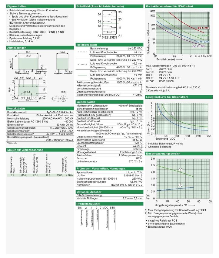
Publisher: SIGMATEK GmbH & Co KG
                                   A-5112 Lamprechtshausen
                                      Tel.: +43/6274/4321
                                    Fax: +43/6274/4321-18
                                   Email: office@sigmatek.at
                               WWW.SIGMATEK-AUTOMATION.COM

                                               Copyright © 2013
                                            SIGMATEK GmbH & Co KG

                                      Translation from German

All rights reserved. No part of this work may be reproduced, edited using an electronic system, duplicated or
distributed in any form (print, photocopy, microfilm or in any other process) without the express permission.

We reserve the right to make changes in the content without notice. The SIGMATEK GmbH & Co KG is not
responsible for technical or printing errors in the handbook and assumes no responsibility for damages that occur
through use of this handbook.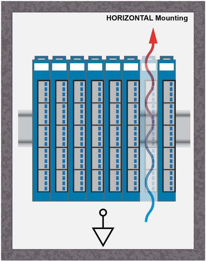
S-DIAS SAFETY RELAY OUTPUT MODULE                     SRO 021

S-DIAS Safety Relay Output Module                                            SRO 021

The S-DIAS Safety SRO 021 relay output module has the safety
integrity level SIL3 (EN / IEC 62061) or Performancelevel e (PL e)
(EN/ISO 13849-1/-2). The SRO 021 has:

2 Safe outputs (EN 61131-2; EN/IEC 62061 und EN ISO 13849-1/-
2)

Both outputs are used for the Safety-oriented closing (NO) of an
electric circuit with a permissible rated voltage of 24 V DC and a
maximum continuous current of 6 A.

The SRO 021 is used for example, for switching higher power loads
or potential-isolated circuits – such as hydraulic valves or the
relaying of emergency stop circuits.

The safety-related SRO 021 is ideal for use in systems with
optional modules and interface variables according to Safety
System Handbook, see homepage1.

To use the SRO 021 in an application, at least one Safety CPU
module that regulates the synchronized communication with the
safety modules using safe bus telegrams is also required. This also
includes

                           •    Processing the safe application and

              •   The distribution of configuration data to remote Safety modules.

1   Using the search function with the keyword “Safety System Handbook”
05.03.2021                                                                            Page 1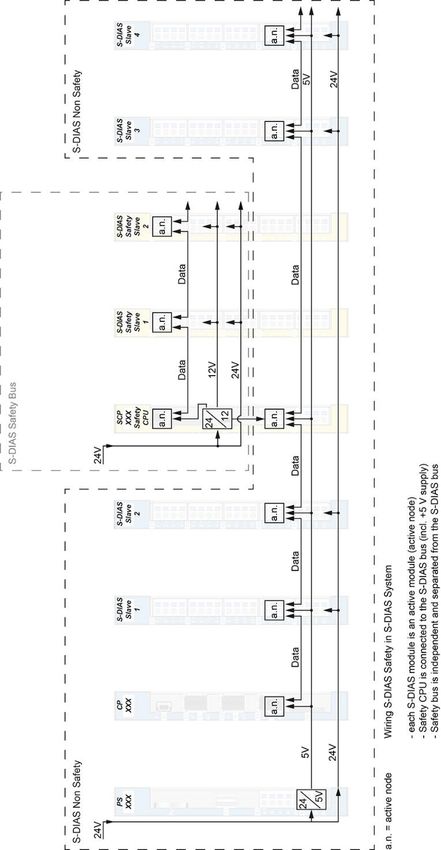
SRO 021       S-DIAS SAFETY RELAY OUTPUT MODULE

Contents
1    Basic Safety Guidelines ......................................................... 4
     1.1          General Information on Safety .................................................... 4

     1.2          Further Safety Guidelines ............................................................ 5

     1.3          General Requirements ................................................................. 6

2    Conformity with EU Guidelines ............................................10
     2.1          Functional Safety Standards ..................................................... 10

     2.2          EU Conformity Declaration ........................................................ 10

     2.3          Safety-Relevant Parameters ...................................................... 11
          2.3.1 Mounting position horizontal 0-55 °C ambient temperature ........................ 11

          2.3.2 Mounting position horizontal 55-60 °C ambient temperature ...................... 11

     2.4          Compatibility ............................................................................... 12

3    Technical Data .......................................................................13
     3.1          Relay Output Specifications ...................................................... 13

     3.2          Lifespan of the Relay Output Module depending on the
                  Number of Switching Cycles Per Year ..................................... 16

     3.3          Relay Circuit ................................................................................ 17

     3.4          Electrical Requirements ............................................................. 17

     3.5          Miscellaneous ............................................................................. 19

     3.6          Environmental Conditions ......................................................... 19

4    Mechanical Dimensions ........................................................20

5    Connector Layout ..................................................................21

Page 2                                                                                              05.03.2021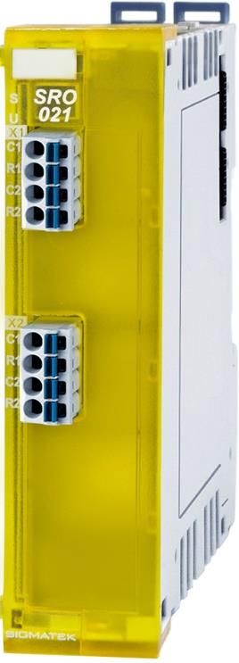
S-DIAS SAFETY RELAY OUTPUT MODULE                                            SRO 021

      5.1        Status LEDs ................................................................................. 22

      5.2        Applicable Connectors ............................................................... 22

      5.3        Label Field ................................................................................... 23

6    Wiring ..................................................................................... 24
      6.1        Wiring Example ........................................................................... 24

      6.2        Note .............................................................................................. 25

7    Mounting ................................................................................ 26

8    Disposal ................................................................................. 28

9    Hardware Class SRO021 ....................................................... 29
      9.1        Interfaces ..................................................................................... 30
         9.1.1        Clients ............................................................................................... 30

         9.1.2        Servers.............................................................................................. 31

         9.1.3        Communication Interfaces ................................................................ 32

      9.2        Example ....................................................................................... 32

05.03.2021                                                                                                           Page 3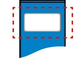
SRO 021       S-DIAS SAFETY RELAY OUTPUT MODULE

1     Basic Safety Guidelines
1.1      General Information on Safety

If the safety guidelines are not followed, dangers to personnel can arise that could lead to
serious injury or in worst cases, death. In less serious cases, systems and equipment can be
damaged.

The following symbols identify the individual risks as well as the degree of seriousness; their
respective meanings are briefly explained. You should therefore familiarize yourself with the
safety symbols and their meanings to prevent dangers and risks.

             DANGER!                   DANGER!
                                       Identifies an immediate danger with high risk, which
                                       can lead to immediate death or serious injury if not
                                       avoided.
                                       Indique un danger direct à haut risque d’un décès
                                       immédiat ou des blessures graves si les consignes de
                                       sécurité ne sont pas respectées.

                                       WARNING
             WARNING
                                       Identifies a possible danger with a mid-level risk, which
                                       can lead to death or (serious) injury if not avoided.

                                       Indique un danger possible d’un risque moyen de
                                       décès ou de (graves) blessures si les consignes de
                                       sécurité ne sont pas respectées.

                                       CAUTION!
             CAUTION!
                                       Identifies a low risk danger, which can lead to injury or
                                       property damage if not avoided.
                                       Indique un danger avec un niveau de risque faible des
                                       blessures légères ou des dommages matériels si les
                                       consignes de sécurité ne sont pas respectées.

Page 4                                                                             05.03.2021
S-DIAS SAFETY RELAY OUTPUT MODULE SRO 021
1.2 Further Safety Guidelines
Warning, dangerous electrical voltage
Avertissement d’une tension électrique dangereuse
Hot surface warning
Avertissement d’une surface chaude
Danger for ESD-sensitive components
Les signes de danger pour les composants sensibles
aux décharges électrostatiques
This symbol identifies important or additional
information regarding the operation of the safety
modules.
Ce symbole indique des informations importantes ou
supplémentaires concernant le fonctionnement des
modules de sécurité particuliers.
05.03.2021 Page 5SRO 021 S-DIAS SAFETY RELAY OUTPUT MODULE
1.3 General Requirements
Technical This technical documentation is a component of this product.
Documentation
• this document must be accessible in the vicinity of the
machine, since it contains important instructions.
• the technical documentation should be included in the
sale, rental or transfer of the product.
Documentation Cette documentation technique fait partie intégrale du produit.
technique
• Gardez la toujours à portée de main et à la proximité de
la machine, car elle contient des informations
importantes.
• Distribuez la documentation technique aux secteurs de
la vente et/ou de la location du produit.
Acceptance of the Before handling the product belonging to this documentation, the
Safety Guidelines operating instructions and safety guidelines must be read.
SIGMATEK GmbH & Co KG accepts no liability for damages
resulting from non-compliance with the safety guidelines or the
relevant regulations.
Acceptance or the safety guidelines and the explanations in this
document, as well as the Safety System handbook are a basic
requirement for proper use. Therefore, read this operating
manual thoroughly and familiarize yourself with each of them.
More information on standards and regulations etc. can be found
in the system handbook.
Prendre connaissance Avant toute manipulation on doit impérativement prendre
de consignes de connaissance de consignes de sécurité et du mode d’emploi.
sécurité SIGMATEK GmbH & Co KG n'assume aucune responsabilité
pour les dommages causés par le non-respect des consignes de
sécurité ou du mode d’emploi respectif.
La connaissance de consignes de sécurité et le contenu de cette
documentation ainsi que le mode d’emploi du système de
sécurité constitue une condition préalable à l'utilisation prévue.
Lisez ce mode d’emploi et assurez-vous de le comprendre
jusqu’aux détails.
Pour plus d'informations sur les normes et les lignes directrices,
etc., reportez-vous au mode d’emploi.
Page 6 05.03.2021S-DIAS SAFETY RELAY OUTPUT MODULE SRO 021
Qualified Personnel Installation, assembly, programming and initial start-up,
operation, maintenance and decommissioning of control and
automation technology products in general, as well as safety-
related products especially, can only be performed by qualified
personnel.
Qualified personnel in this context are people, who have
completed training or have trained under supervision of qualified
personnel and have been authorized to operate and maintain
safety-related equipment, systems and facilities in compliance
with the strict guidelines and standards of safety technology.
Personnel qualifié Installation, montage, programmation, mise en service,
l'exploitation, l'entretien et mise hors service de produits de
commande et d'automatisation en général, et de produits liés à
la sécurité, en particulier, ne peut être effectuée que par le
personnel qualifié.
On entend sous terme personnel qualifié les personnes ayant
acquis une formation professionnelle dispensé par un spécialiste
sur l’utilisation et surveillance des composants et des systèmes
de sécurité, ceci conformément aux lignes directrices et les
normes en vigueur.
05.03.2021 Page 7SRO 021 S-DIAS SAFETY RELAY OUTPUT MODULE
Designated Use The Safety modules are designed for use in safety-oriented
applications and meet the required conditions for safety
operation in compliance with Performance level e (PL e), in
accordance with EN ISO 13849-1/-2 and SIL3 in accordance with
EN 62061.
For your own safety and the safety of others, use safety modules
for their designated purpose. Correct EMC installation as well as
proper transport and storage are also included in designated use.
Non-designated use consists of
• any change made to the safety modules of any kind.
• the use of damaged safety modules.
• the use of the safety module outside of the instructions
described in this handbook.
• the use of the safety module outside of the technical
data described in this handbook.
Utilisation prévue Les modules de sécurité sont conçus pour une utilisation dans
les applications sollicitant un niveau de sécurité et répondent à
toutes les conditions nécessaires pour un fonctionnement sûr
conformément au niveau de performance e (PL e) selon la norme
EN ISO 13849-1/-2 et SIL3 de la norme EN 62061.
Utilisez le module de sécurité conformément à son mode
d’emploi pour votre propre sécurité et celle d'autres personnes.
L'utilisation conforme comprend également une installation
conforme CEM ainsi que le transport et le stockage conforme.
L'utilisation abusive comprend entre autres:
• les modifications quelconques apportées aux modules
de sécurité.
• utilisation de modules de sécurité endommagés.
• utilisation de modules de sécurité en dehors du cadre
décrit dans ce mode d’emploi.
• utilisation de modules de sécurité en dehors des
spécifications décrites dans ce mode d’emploi.
Page 8 05.03.2021S-DIAS SAFETY RELAY OUTPUT MODULE SRO 021
Operator Due Diligence
The operator must ensure that
• the Safety modules are to be used for their designated
purpose only.
• the Safety modules are to be operated in error-free, fully
functional condition only.
• only sufficiently qualified and authorized personnel my
operated the Safety modules.
• the documentation is complete and in readable
condition and available at the site of operation.
Obligation de diligence
L’utilisateur doit s'assurer que
• les modules de sécurité ne sont utilisés que selon les
spécifications.
• uniquement les modules de sécurité en parfait état de
fonctionnement peuvent être utilisés.
• seulement le personnel qualifié et autorisé puisse
manipuler les modules de sécurité.
• la documentation dans son intégralité et dans un état
lisible est mise à disposition à l’endroit où les modules
de sécurité sont utilisés.
05.03.2021 Page 9SRO 021 S-DIAS SAFETY RELAY OUTPUT MODULE
2 Conformity with EU Guidelines
2.1 Functional Safety Standards
- EN / IEC 62061:2005/A2:2015
- EN ISO 13849-1:2015
- EN ISO 13849-2:2012
2.2 EU Conformity Declaration
EU Declaration of Conformity
The product SRO 021 complies with the following European directives:
• 2006/42/EG machine guideline
• 2014/30/EU Electromagnetic Compatibility (EMC guideline)
• 2011/65/EU Restricted use of certain hazardous substances in
electrical and electronic equipment (RoHS Guideline)
The EU Conformity Declarations are provided on the SIGMATEK website.
Using the search function with the keyword “EU Declaration of Conformity”.
Page 10 05.03.2021S-DIAS SAFETY RELAY OUTPUT MODULE SRO 021
2.3 Safety-Relevant Parameters
2.3.1 Mounting position horizontal 0-55 °C ambient temperature
Relay Module Safety Parameters Safety Levels
SRO 021 including CPU module PFHD = 9.7E-09 (1/h) PL e / Cat. 4
SCP 011/SCP 111
MTTFD = 240 years SIL 3
DC = 98 %
SFF = 99 %
The above failure probability (PFHD, MTTFD and SFF)) is based on the assumption that the
output relay is operated with 25.000 switching cycles per year (nop). If more switching cycles
per year are required, you can request the safety parameters from SIGMATEK via the
support.
2.3.2 Mounting position horizontal 55-60 °C ambient temperature
Relay Module Safety Parameters Safety Levels
SRO 021 including CPU-module PFHD = 1.0E-08 (1/h) PL e / Kat. 4
SCP 011/SCP 111
MTTFD = 233 years SIL 3
DC = 98 %
SFF = 99 %
The above failure probability (PFHD, MTTFD and SFF)) is based on the assumption that the
output relay is operated with 25.000 switching cycles per year (nop). If more switching
cycles per year are required, you can request the safety parameters from SIGMATEK via
the support.
Time of use of the relay output module depending on the
number of switching cycles per year, see chapter 3.2.
05.03.2021 Page 11SRO 021 S-DIAS SAFETY RELAY OUTPUT MODULE
2.4 Compatibility
For compatibility of the S-DIAS Safety modules, see section
Compatibility "Compatibility of S-DIAS Safety Modules" in the system
handbook.
Page 12 05.03.2021S-DIAS SAFETY RELAY OUTPUT MODULE SRO 021
3 Technical Data
3.1 Relay Output Specifications
Number 2
Configuration two-channel
Voltage range maximum +30 V
Contact current maximum 6 A at 55 °C
maximum 4 A at 60 °C
Miscellaneous no protective circuit
This module exceeds the defined current consumption for S-DIAS Safety modules,
therefore it should be considered as two S-DIAS Safety modules.
05.03.2021 Page 13SRO 021 S-DIAS SAFETY RELAY OUTPUT MODULE
Relays of the HW versions ≤3.00:
Attention!
The module SRO 021 is only designed for a maximum voltage range of +30 V.
Page 14 05.03.2021S-DIAS SAFETY RELAY OUTPUT MODULE SRO 021
Relays of the HW versions ≥3.00:
Attention!
The module SRO 021 is only designed for a maximum voltage range of +30 V.
05.03.2021 Page 15SRO 021 S-DIAS SAFETY RELAY OUTPUT MODULE
3.2 Lifespan of the Relay Output Module depending on the Number of
Switching Cycles Per Year
20
50000
Verwendungszeit in Jahren
15.6
15
Operating Time in Years
B10D
10
nop
5
0
5 5 5 5
0 2 10 4 10 6 10 8 10
nop
Switching Cycles per Year
Sc haltspiele pro Jahr
Duration of relay output module use 20a
B10D-value of the relay used 780000 switching cycles under rated load
Example calculation: With 50000 switching cycles per year, the relay output module must
be exchanged after 15.6 years (=);
B10D
with 39000 = 15.6 switching cycles per year, the lifespan is 20 years.
50000
Page 16 05.03.2021S-DIAS SAFETY RELAY OUTPUT MODULE SRO 021 3.3 Relay Circuit The outputs are internally wired as a series circuit of to two relays. 3.4 Electrical Requirements Voltage supply from Safety bus +12 V Current consumption on Safety typically 30 mA maximum 40 mA bus (+12 V supply) Voltage supply from Safety bus +24 V Current consumption on Safety typically 90 mA maximum 100 mA bus (+24 V supply) If this S-DIAS Safety module is connected to an SCP with several modules, the total current of the S-DIAS Safety modules used must be determined and checked. The total current of the +24 V supply cannot exceed 800 mA. The total current of the +12 V supply cannot exceed 800 mA. Si ce module S-DIAS Safety est connecté à un SCP avec plusieurs modules S-DIAS, le courant total des modules utilisés doit être défini et contrôlé. Le courant total de l'alimentation +24 V ne peut pas dépasser 800 mA! Le courant total de l'alimentation +12 V ne peut pas dépasser 800 mA! The S-DIAS Safety CPU Module supports a maximum of 16 safe I/O modules. The S-DIAS Safety Relay Module SRO 021 corresponds to two safe I/O modules. L'automate de sécurité CPU S-DIAS prend en charge 16 E / S de sécurité au maximum. Le S-DIAS module relais de sécurité SRO 021 correspond à deux modules simples E / S de sécurité. 05.03.2021 Page 17
SRO 021   S-DIAS SAFETY RELAY OUTPUT MODULE

Page 18                                       05.03.2021
S-DIAS SAFETY RELAY OUTPUT MODULE                                  SRO 021

3.5     Miscellaneous

  Article number                                                   20-893-021

  Hardware version                                              1.00 / 2.00 / 3.xx

  Standard                                                         EN 62061 SIL 3

                                                             EN ISO 13849-1 PL e/Cat. 4

                                                               UL 508 (E247993)

  Approbations                                       CE, TÜV EC type-examination tested, CULUS

3.6     Environmental Conditions

  Storage temperature                                             -20 ... +85 °C

  Environmental temperature                                     0 ... +55 °C (UL)

                                            +55 … +60 °C with derating since HW version 3.10 (CE)

  Humidity                                                   0-95 %, non-condensing

  Installation altitude above sea                          0-2000 m without derating
  level
                                    > 2000 m with derating of the maximum environmental temperature by 0.5
                                                                  °C per 100 m

  Operating conditions                                         Pollution degree 2

  EMC resistance                        in accordance with 61000-6-7:2015 (Generic standards - Immunity
                                    requirements for equipment intended to perform functions in safety-related
                                                 systems (functional safety) at industrial locations)

                                             in accordance with EN 61000-6-2:2007 (industrial area)
                                             (increased requirements in accordance with IEC 62061)

  EMC noise generation                       in accordance with EN 61000-6-4:2007 (industrial area)

  Vibration resistance                        EN 60068-2-6                           3.5 mm from 5-8.4 Hz
                                                                                      1 g from 8.4-150 Hz

  Shock resistance                           EN 60068-2-27                                  15 g

  Protection type                               EN 60529                                    IP20

05.03.2021                                                                                              Page 19
SRO 021 S-DIAS SAFETY RELAY OUTPUT MODULE 4 Mechanical Dimensions Page 20 05.03.2021
S-DIAS SAFETY RELAY OUTPUT MODULE   SRO 021

5   Connector Layout

05.03.2021                                                 Page 21
SRO 021           S-DIAS SAFETY RELAY OUTPUT MODULE

5.1      Status LEDs

  Bus Status            green       ON                 bus communication OK

                                    OFF                no supply available

                                    BLINKING (5 Hz)    no communication

  Safety-Used           yellow      ON                 module is used and no error

                                    OFF                module is not used or not in operational mode

  Output Status         yellow      ON                 output ON

                                    OFF                output ON

5.2      Applicable Connectors
                                        Connectors:
X1, X2: Connectors with spring terminals (included in delivery)
The spring terminals are suitable connecting ultrasonically compacted (ultrasonically welded)
strands.

Connections:
  Stripping length/Sleeve length:                                       10 mm
  Plug-in direction:                                                    parallel to conductor axis or to PCB
  Conductor cross section, rigid:                                       0.2-1.5 mm2
  Conductor cross section, flexible:                                    0.2-1.5 mm2
  Conductor cross section, ultrasonically compacted:                    0.2-1.5 mm2
  Conductor cross section AWG/kcmil:                                    24-16
  Conductor cross section flexible, with ferrule without plastic        0.25-1.5 mm2
   sleeve:
  Conductor cross section flexible, with ferrule with plastic sleeve:   0.25-0.75 mm2 (ground for reducing d2 of the
                                                                        ferrule)

Page 22                                                                                                   05.03.2021
S-DIAS SAFETY RELAY OUTPUT MODULE SRO 021 5.3 Label Field Manufacturer Weidmüller Type MF 10/5 CABUR MC NE WS Weidmüller article number 1854510000 Compatible printer Weidmüller Type Printjet Advanced 230V Weidmüller article number 1324380000 05.03.2021 Page 23
SRO 021     S-DIAS SAFETY RELAY OUTPUT MODULE

6     Wiring
6.1    Wiring Example

Page 24                                         05.03.2021
S-DIAS SAFETY RELAY OUTPUT MODULE                   SRO 021

6.2      Note
    The input filters, which suppress noise signals, allow operation in harsh environmental
    conditions. A careful wiring method is also recommended to ensure error-free function.

The following installation guidelines should be observed:

•     Avoid parallel connections between input lines and load-bearing circuits.

•     Protective circuits for all relays (RC networks or free-wheeling diodes)

•     Correct wiring to ground

       The ground bus should be connected to the control cabinet when possible!

             Si possible la terre doit être connectée à l'armoire de commande!

               The wiring and assembly must be performed when no voltage is applied!

               Le câblage et l'installation ne doivent être effectués que sur un système hors
               tension !

                               IMPORTANT:
The S-DIAS module CANNOT be connected or disconnected while voltage is applied!

                                    IMPORTANT:
            Le module S-Dias NE PEUT PAS être inséré ou retiré sous tension.

05.03.2021                                                                             Page 25
SRO 021 S-DIAS SAFETY RELAY OUTPUT MODULE 7 Mounting The S-DIAS modules are designed for installation into the control cabinet. To mount the modules a DIN-rail is required. The DIN rail must establish a conductive connection with the back wall of the control cabinet. The individual S-DIAS modules are mounted on the DIN rail as a block and secured with latches. The functional ground connection from the module to the DIN rail is made via the grounding clamp on the back of the S-DIAS modules. The modules must be mounted horizontally (module label up) with sufficient clearance between the ventilation slots of the S-DIAS module blocks and nearby components and/or the control cabinet wall. This is necessary for optimal cooling and air circulation, so that proper function up to the maximum operating temperature is ensured. Page 26 05.03.2021
S-DIAS SAFETY RELAY OUTPUT MODULE          SRO 021

Recommended minimum distances of the S-DIAS modules to the surrounding components
or control cabinet wall:

a, b, c … distances in mm (inches)

05.03.2021                                                                Page 27
SRO 021       S-DIAS SAFETY RELAY OUTPUT MODULE

8    Disposal
For the disposal of the product, the respective guidelines, possibly country-specific, must be
                                   observed and followed.

Page 28                                                                           05.03.2021
S-DIAS SAFETY RELAY OUTPUT MODULE SRO 021 9 Hardware Class SRO021 Hardware Class SRO021 for the S-DIAS STO 081 digital output module This hardware class is used to control the SRO 021 hardware module with 2 Safe digital outputs. More information on the hardware can be found in the module documentation. 05.03.2021 Page 29
SRO 021       S-DIAS SAFETY RELAY OUTPUT MODULE

9.1     Interfaces
9.1.1     Clients

                    SdiasSafetyIn The client must be connected to a Save S-DIAS port, an
                                  "SdiasSafetyOut_[x]” server.
                            Place The physical location of the hardware module is entered in this client. Up to
                                  16 modules, 0 to 15, can be assigned.
                        Required This client is active by default, which means that the S-DIAS hardware
                                 module at this position is mandatory for the system and can under no
                                 circumstances be disconnected or return an error. Otherwise, the entire
                                 hardware deactivated. If the hardware module is missing or removed, an S-
                                 DIAS error is triggered. If his client is initialized with 0, the hardware module
                                 located in this position is not mandatory. This means that it doesn't have to
                                 be available or error-free. However, which components identified as "not
                                 required" should be selected with regard to the safety of the system.

Page 30                                                                                               05.03.2021
S-DIAS SAFETY RELAY OUTPUT MODULE SRO 021
9.1.2 Servers
ClassState This server shows the actual status of the hardware class.
DeviceID The device ID of the hardware module is shown in this server.
Hardware Version Hardware version of the module in the format 16#XXYY (e.g. 16#0120 =
version 1.20)
If 0 is shown here, the display of the hardware version is not supported by
the used firmware.
SerialNo The serial number of the hardware module is shown in this server.
SafetyNumber Shows the unique Safety number of the module.
RetryCounteruC1 Shows the current number of retries by microprocessor 1.
-1 The operating system does not yet support reading the retry
counter.
RetryCounteruC2 Shows the current number of retries by microprocessor 2.
-1 The operating system does not yet support reading the retry
counter.
QuitComError A communication error is canceled by writing to this server. If the safety.dlm
is used, the dlm can also cancel other errors starting with version 6.
The canceling of errors is forwarded to the Safety CPU and canceled with all
other errors in the Safety CPU.
Caution!
Canceling can activate safety outputs and thereby lead to unexpected
responses from machine elements.
If this function is provided through the visualization, a corresponding warning
should be displayed.
The server shows the status of the cancellation:
2 Busy canceling error
1 Busy canceling communication error
0 Ready
-1 Error creating Safety statement via dlm
-2 Deactivation of user input request failed.
-3 Selection of module via Safety number failed
-4 Error during connection set-up with module via dlm (the
SafetyDesigner cannot be online while canceling errors!)
-5 Error canceling in the module failed
-6 Remove the Safety statement via dlm failed
Safe_Output[1-2] Status of safe digital outputs 1 to 2.
UnSafe_Output[1-2] With this server, the respective Safe output can be switched as long as in
the output settings in the SafetyDesigner, the "Enable Signal Used" property
is set to true.
SafeIOError Shows which safe outputs are in error mode with a bit code
E.g.: Bit0 = Output 1, Bit1 = Output 2,...
05.03.2021 Page 31SRO 021 S-DIAS SAFETY RELAY OUTPUT MODULE
9.1.3 Communication Interfaces
ALARM Downlink With this downlink the corresponding alarm class can be placed via the
hardware editor.
9.2 Example
Page 32 05.03.2021S-DIAS SAFETY RELAY OUTPUT MODULE SRO 021
Documentation Changes
Change date Affected Chapter Note
page(s)
11.02.2014 14 5 Connector Layout Changed image
15 5.2 Applicable Connectors Connection capacity added
French notes added
03.03.2014 16 5 Connector Layout Changed image
17 5.1 Status LEDs Changed/expanded Status LEDs table
01.04.2014 20 7 Mounting Text updated
20.05.2014 13 3.4 Electrical Requirements Note added
23.05.2014 10 2.3 Compatibility Added chapter
08.09.2014 14 3.5 Miscellaneous Added Standard
13.01.2015 13 3.4 Electrical Requirements Changed 2nd notice
30.01.2015 19 6.2 Note Added note concerning connecting the S-DIAS
module while voltage is applied
26.03.2015 17 5.2 Applicable Connectors Added connections
07.05.2015 New writing: EN ISO 13849-1/-2
18.05.2015 14 3.6 Environmental Conditions Expanded vibration resistance
27.05.2015 new cover, pictures changed
01.07.2015 12 3.1 Relay Output Added new data sheet
Specifications
04.08.2015 Info Cover Translation from German added
09.03.2016 15 3.4 Electrical Requirements Graphics
28.04.2016 23 7 Mounting Graphics distances
28.06.2017 12 3.1 Relay Output Note added
Specification
17.08.2017 16 3.6 Environmental Conditions Pollution Degree
19 5.2 Applicable Connectors Sleeve length added
Added info regarding ultrasonically welded strands
18.10.2017 20 5.3 Label Field Added chapter
24 7 Mounting Graphic replaced
05.03.2021 Page 33SRO 021 S-DIAS SAFETY RELAY OUTPUT MODULE
16.11.2017 10 2 Conformity with EU SCP 111 values added
Guidelines
02.04.2019 10 2.3 Safety-Relevant Values adjusted
Parameters
17 3.6 Environmental Conditions Corrections
all Corrections due to CE
14.11.2019 8 Supported Cycle Times Chapter added
02.12.2019 2.3 Safety-Relevant Values updated
Parameters
28.02.2020 26 8 Supported Cycle Times Text adapted
28.05.2020 26 8 Supported Cycle Times Chapter removed
23.07.2020 1 Introductory text changed
19.08.2020 1 SIL CL 3 removed
10 2.2 EU Conformity adapted
Declaration
11 2.3 Safety-Relevant Sub-chapter added
Parameters
13 3.1 Relay Output Contact current adapted
Specifications
14 3.1 Relay Output Headline added
Specifications
15 3.1 Relay Output New data sheet inserted
Specifications
19 3.5 Miscellaneous Standard adapted
19 3.6 Environmental Conditions Environmental temperature adapted
02.09.2020 19 3.6 Environmental Conditions At Environmental temperature "since HW version
3.10" added
08.09.2020 29 9 Hardware Class SRO021 Chapter added
04.11.2020 26 7 Mounting Expansion functional ground connection
19.11.2020 15 3.1 Relay Output Warning note inserted under the relay data sheet
Specifications
05.03.2021 3.6 Environmental Conditions Standards added
Page 34 05.03.2021Vous pouvez aussi lire