SCP 011 S-DIAS Safety CPU Module - Sigmatek
←
→
Transcription du contenu de la page
Si votre navigateur ne rend pas la page correctement, lisez s'il vous plaît le contenu de la page ci-dessous
SCP 011
        S-DIAS Safety CPU Module

Date of creation: 18.12.2013   Version date: 08.09.2020   Article number: 20-890-011-E
Publisher: SIGMATEK GmbH & Co KG
                                   A-5112 Lamprechtshausen
                                      Tel.: +43/6274/4321
                                    Fax: +43/6274/4321-18
                                   Email: office@sigmatek.at
                               WWW.SIGMATEK-AUTOMATION.COM

                                              Copyright © 2013
                                           SIGMATEK GmbH & Co KG

                                      Translation from German

All rights reserved. No part of this work may be reproduced, edited using an electronic system, duplicated or
distributed in any form (print, photocopy, microfilm or in any other process) without the express permission.

We reserve the right to make changes in the content without notice. The SIGMATEK GmbH & Co KG is not responsible
for technical or printing errors in the handbook and assumes no responsibility for damages that occur through use
of this handbook.
S-DIAS SAFETY CPU MODULE               SCP 011

S-DIAS Safety CPU Module                                                       SCP 011

The S-DIAS 011 Safety CPU module supports up to 16 Safe IO modules.
In addition, the SCP 011 can operate handheld devices with Emergency
Stop and/or confirmation buttons.

The Safety CPU component has the safety integrity level SIL3 or SIL CL
3 (EN / IEC 62061) or Performancelevel e (PL e) (EN ISO 13849-1/-2).

The safety-related SCP 011 is ideal for use in systems with optional
modules and interface variables according to Safety System Handbook,
see homepage1.

The SCP 011 module alone is already a minimal system of a safety
control.

In addition, the SCP 011 regulates the synchronized communication with
the remote safety modules through safe bus telegrams. This also includes
         •   processing the safe application and
         •   the distribution of configuration data to remote Safety modules

1   Using the search function with the keyword “Safety System Handbook”
08.09.2020                                                                        Page 1
SCP 011             S-DIAS SAFETY CPU MODULE

Contents
1    Basic Safety Guidelines ......................................................... 5
     1.1          General Information on Safety .................................................... 5

     1.2          Further Safety Guidelines ............................................................ 6

     1.3          General Requirements ................................................................. 7

2    Safety Conformity ..................................................................11
     2.1          Functional Safety Standards ..................................................... 11

     2.2          EU Conformity Declaration ........................................................ 11

     2.3          Safety-Relevant Parameters ...................................................... 12
          2.3.1        Mounting Position Horizontal 0-55 °C Ambient Temperature ............ 12

          2.3.2        Mounting Position Horizontal 55-60 °C Ambient Temperature .......... 12

     2.4          Compatibility ............................................................................... 13

3    Technical Data .......................................................................14
     3.1          Performance Data ....................................................................... 14

     3.2          Electrical Requirements ............................................................. 14
          3.2.1        Module Supply (Input) ....................................................................... 14

          3.2.2        S-DIAS Bus/Safety Supply (Output) .................................................. 15

     3.3          Miscellaneous ............................................................................. 18

     3.4          Environmental Conditions ......................................................... 18

4    Mechanical Dimensions ........................................................19

5    Connector Layout ..................................................................20
     5.1          Status LEDs ................................................................................. 21

Page 2                                                                                                 08.09.2020
S-DIAS SAFETY CPU MODULE SCP 011
5.2 Applicable Connectors ............................................................... 22
5.3 Label Field ................................................................................... 23
6 Validation Button................................................................... 24
6.1 Explanation of the Individual Sequences ................................. 24
6.1.1 Start Sequence ................................................................................. 24
6.1.2 Command Selection Sequence......................................................... 25
6.1.3 End Sequence .................................................................................. 25
6.1.4 Error Sequence ................................................................................. 26
6.2 Overview of Commands ............................................................. 27
6.3 Overview of Module Statuses and Commands ........................ 27
6.4 Handling the microSD Card ....................................................... 29
6.5 Configuring a Safety CPU with the SD Card ............................ 30
7 Error Response ..................................................................... 32
7.1 Restart Errors .............................................................................. 32
7.2 Configuration Distribution Error ............................................... 33
7.3 Troubleshooting .......................................................................... 34
7.4 Troubleshooting with the SafetyDesigner ............................... 34
7.5 Correcting a Wiring Error ........................................................... 34
8 Wiring Guidelines .................................................................. 35
9 Mounting ................................................................................ 36
10 Supported Cycle Times ........................................................ 38
10.1 Cycle Times below 1 ms (in µs) ................................................. 38
08.09.2020 Page 3SCP 011 S-DIAS SAFETY CPU MODULE
10.2 Cycle Times equal to or higher than 1 ms (in ms) .................. 38
11 Disposal ..................................................................................38
12 Hardware Class SCP011........................................................39
12.1 General......................................................................................... 40
12.2 Safety ........................................................................................... 41
12.3 Communication Interfaces......................................................... 43
12.4 Global Methods ........................................................................... 44
12.4.1 FetchDiagState .................................................................................. 44
12.4.2 GetDiagState ..................................................................................... 44
12.4.3 FetchDiagInfo .................................................................................... 44
12.4.4 GetDiagInfo ....................................................................................... 44
12.4.5 SaveLog ............................................................................................ 45
12.4.6 SaveLogActive................................................................................... 45
12.5 Internal units ............................................................................... 45
Page 4 08.09.2020S-DIAS SAFETY CPU MODULE SCP 011
1 Basic Safety Guidelines
1.1 General Information on Safety
If the safety guidelines are not followed, dangers to personnel can arise that could lead to
serious injury or in worst cases, death. In less serious cases, systems and equipment can be
damaged.
The following symbols identify the individual risks as well as the degree of seriousness; their
respective meanings are briefly explained. You should therefore familiarize yourself with the
safety symbols and their meanings to prevent dangers and risks.
DANGER! DANGER!
Identifies an immediate danger with high risk, which
can lead to immediate death or serious injury if not
avoided.
Indique un danger direct à haut risque d’un décès
immédiat ou des blessures graves si les consignes de
sécurité ne sont pas respectées.
WARNING
WARNING
Identifies a possible danger with a mid-level risk, which
can lead to death or (serious) injury if not avoided.
Indique un danger possible d’un risque moyen de
décès ou de (graves) blessures si les consignes de
sécurité ne sont pas respectées.
CAUTION!
CAUTION!
Identifies a low risk danger, which can lead to injury or
property damage if not avoided.
Indique un danger avec un niveau de risque faible des
blessures légères ou des dommages matériels si les
consignes de sécurité ne sont pas respectées.
08.09.2020 Page 5SCP 011 S-DIAS SAFETY CPU MODULE
1.2 Further Safety Guidelines
Warning, dangerous electrical voltage
Avertissement d’une tension électrique dangereuse
Hot surface warning
Avertissement d’une surface chaude
Danger for ESD-sensitive components
Les signes de danger pour les composants sensibles
aux décharges électrostatiques
This symbol identifies important or additional
information regarding the operation of the safety
modules.
Ce symbole indique des informations importantes ou
supplémentaires concernant le fonctionnement des
modules de sécurité particuliers.
Page 6 08.09.2020S-DIAS SAFETY CPU MODULE SCP 011
1.3 General Requirements
Technical This technical documentation is a component of this product.
Documentation
• this document must be accessible in the vicinity of the
machine, since it contains important instructions.
• the technical documentation should be included in the
sale, rental or transfer of the product.
Documentation Cette documentation technique fait partie intégrale du produit.
technique
• Gardez la toujours à portée de main et à la proximité de
la machine, car elle contient des informations
importantes.
• Distribuez la documentation technique aux secteurs de
la vente et/ou de la location du produit.
Acceptance of the Before handling the product belonging to this documentation, the
Safety Guidelines operating instructions and safety guidelines must be read.
SIGMATEK GmbH & Co KG accepts no liability for damages
resulting from non-compliance with the safety guidelines or the
relevant regulations.
Acceptance or the safety guidelines and the explanations in this
document, as well as the Safety System handbook are a basic
requirement for proper use. Therefore, read this operating
manual thoroughly and familiarize yourself with each of them.
More information on standards and regulations etc. can be found
in the system handbook.
08.09.2020 Page 7SCP 011 S-DIAS SAFETY CPU MODULE
Prendre connaissance Avant toute manipulation on doit impérativement prendre
de consignes de connaissance de consignes de sécurité et du mode d’emploi.
sécurité SIGMATEK GmbH & Co KG n'assume aucune responsabilité
pour les dommages causés par le non-respect des consignes de
sécurité ou du mode d’emploi respectif.
La connaissance de consignes de sécurité et le contenu de cette
documentation ainsi que le mode d’emploi du système de
sécurité constitue une condition préalable à l'utilisation prévue.
Lisez ce mode d’emploi et assurez-vous de le comprendre
jusqu’aux détails.
Pour plus d'informations sur les normes et les lignes directrices,
etc., reportez-vous au mode d’emploi.
Qualified Personnel Installation, assembly, programming and initial start-up,
operation, maintenance and decommissioning of control and
automation technology products in general, as well as safety-
related products especially, can only be performed by qualified
personnel.
Qualified personnel in this context are people, who have
completed training or have trained under supervision of qualified
personnel and have been authorized to operate and maintain
safety-related equipment, systems and facilities in compliance
with the strict guidelines and standards of safety technology.
Personnel qualifié Installation, montage, programmation, mise en service,
l'exploitation, l'entretien et mise hors service de produits de
commande et d'automatisation en général, et de produits liés à
la sécurité, en particulier, ne peut être effectuée que par le
personnel qualifié.
On entend sous terme personnel qualifié les personnes ayant
acquis une formation professionnelle dispensé par un spécialiste
sur l’utilisation et surveillance des composants et des systèmes
de sécurité, ceci conformément aux lignes directrices et les
normes en vigueur.
Page 8 08.09.2020S-DIAS SAFETY CPU MODULE SCP 011
Designated Use The Safety modules are designed for use in safety-oriented
applications and meet the required conditions for safety
operation in compliance with Performance level e (PL e), in
accordance with EN ISO 13849-1/-2 and SIL3 or SIL CL 3 in
accordance with EN 62061.
For your own safety and the safety of others, use safety modules
for their designated purpose. Correct EMC installation as well as
proper transport and storage are also included in designated use.
Non-designated use consists of
• Any change made to the safety modules of any kind.
• The use of damaged safety modules.
• The use of the safety module outside of the instructions
described in this handbook.
• The use of the safety module outside of the technical
data described in this handbook.
Utilisation prévue Les modules de sécurité sont conçus pour une utilisation dans
les applications sollicitant un niveau de sécurité et répondent à
toutes les conditions nécessaires pour un fonctionnement sûr
conformément au niveau de performance e (PL e) selon la norme
EN ISO 13849-1/-2 et SIL3 ou SIL CL 3 de la norme EN 62061.
Utilisez le module de sécurité conformément à son mode
d’emploi pour votre propre sécurité et celle d'autres personnes.
L'utilisation conforme comprend également une installation
conforme CEM ainsi que le transport et le stockage conforme.
L'utilisation abusive comprend entre autres:
• Les modifications quelconques apportées aux modules
de sécurité.
• Utilisation de modules de sécurité endommagés.
• Utilisation de modules de sécurité en dehors du cadre
décrit dans ce mode d’emploi.
• Utilisation de modules de sécurité en dehors des
spécifications décrites dans ce mode d’emploi.
08.09.2020 Page 9SCP 011 S-DIAS SAFETY CPU MODULE
Operator Due Diligence The operator must ensure that
• The Safety modules are to be used for their designated
purpose only.
• The Safety modules are to be operated in error-free,
fully functional condition only.
• Only sufficiently qualified and authorized personnel my
operated the Safety modules.
The documentation is complete and in readable condition and
available at the site of operation.
Obligation de diligence L’utilisateur doit s'assurer que
• les modules de sécurité ne sont utilisés que selon les
spécifications.
• uniquement les modules de sécurité en parfait état de
fonctionnement peuvent être utilisés.
• seulement le personnel qualifié et autorisé puisse
manipuler les modules de sécurité.
la documentation dans son intégralité et dans un état lisible est
mise à disposition à l’endroit où les modules de sécurité sont
utilisés.
Page 10 08.09.2020S-DIAS SAFETY CPU MODULE SCP 011
2 Safety Conformity
2.1 Functional Safety Standards
- EN / IEC 62061:2005/A2 2015
- EN ISO 13849-1:2015
- EN ISO 13849-2:2012
2.2 EU Conformity Declaration
CE Declaration of Conformity
The SCP 011 complies with the following European directives:
• 2006/42/EG “Directive of the European Parliament and of the
Council of 17 May 2006 on Machinery and Change to the Directive
95/16/EC” (machine guideline)
• 2014/30/EU “Electromagnetic Compatibility” (EMC guideline)
• 2011/65/EU Restricted use of certain hazardous substances in
electrical and electronic equipment (RoHS Guideline)
The EU Conformity Declarations are provided on the SIGMATEK website.
Using the search function with the keyword “EU Declaration of Conformity”.
08.09.2020 Page 11SCP 011 S-DIAS SAFETY CPU MODULE
2.3 Safety-Relevant Parameters
2.3.1 Mounting Position Horizontal 0-55 °C Ambient Temperature
CPU Module Safety Parameters Safety Levels
SCP 011 PFHD = 1,4E-10 (1/h) SIL 3
according to EN/IEC 62061
MTTFD = 2689 years
PL e / Cat. 4
DC = 99 % according to EN ISO 13849-1/-2
SFF = 99 %
Structure: Two-channel redundant (diverse)
2.3.2 Mounting Position Horizontal 55-60 °C Ambient Temperature
CPU Module Safety Parameters Safety Levels
SCP 011 PFHD = 1,7E-10 (1/h) SIL 3
according to EN/IEC 62061
MTTFD = 2243 years
PL e / Cat. 4
DC = 99 % according to EN ISO 13849-1/-2
SFF = 99 %
Structure: Two-channel redundant (diverse)
Page 12 08.09.2020S-DIAS SAFETY CPU MODULE SCP 011
2.4 Compatibility
The safety-related module SCP 011 is supported with firmware version V334 and build No.
1156 or higher of the Safety Designer.
Use of Safe Analog Values (SAFEDINT):
If Safe analog values (variables of type SAFEDINT) are transferred and further processed,
an SCP011 with Firmware version V344 or higher MUST be used (HW version 1.60).
SAFEDINT variables are transferred when for two or more Safety CPU's in a project,
SAFEDINT values are placed in the networks of the remote Safety CPU or with the use of
SAFEDINT values in interface frames (safe variables).
Compatibility For compatibility of the S-DIAS Safety modules, see section
"Compatibility of S-DIAS Safety Modules" in the system
handbook.
08.09.2020 Page 13SCP 011 S-DIAS SAFETY CPU MODULE
3 Technical Data
3.1 Performance Data
Interfaces 1x Safety Interface
Program interfaces 1x USB device
Bus connection possible yes
Miscellaneous microSD slot
Supply voltage +24 V
3.2 Electrical Requirements
3.2.1 Module Supply (Input)
Supply voltage +18-30(5) V DC, typically +24 V DC
UL: Class 2 or LVLC(1)
Current, internal consumption typically 90 mA internal consumption
maximum 1.4 A (2) (3)
Current consumption +5 V +24 V
from the S-DIAS bus
with missing typically maximu 0A 0A
+24 V connection (X3) 170 mA m
200 mA
with existing 0A 0A 0A 0A
+24 V connection (X3)
A fuse for the supply voltage must be installed, which can sufficiently limit voltage
and current.
Un fusible conforme aux limites de la tension et du courant d'alimentation doit être
présent en amont de l'alimentation.
Page 14 08.09.2020S-DIAS SAFETY CPU MODULE SCP 011
3.2.2 S-DIAS Bus/Safety Supply (Output)
Voltage supply in the +5 V +24 V
S-DIAS bus
0A 0A
in the +12 V +24 V
S-DIAS Safety bus
(2) (4)
(supply of the I/O modules) max. 0.8 A max. 0.8 A (2) (4)
______________
(1) For USA and Canada:
The supply must be limited to:
a) max. 5 A at voltages from 0-20 V DC, or
b) 100 W at voltages from 20-60 V DC
The limiting component (e.g. transformer, power supply or fuse) must be certified by an NRTL
(Nationally Recognized Testing Laboratory).
(1) Pour les États-Unis et le Canada:
L’alimentation doit être limitée à:
a) max. 5 A pour des tensions de 0-20 V DC, ou
b) 100 W pour des tensions de 20-60 V DC
Le composant imposant la limite (par exemple, transformateur, alimentation électrique ou
fusible) doit être certifié par un NRTL (National Recognized Testing Laboratory, par exemple,
UL).
(2) dependent on the number of connected modules on the S-DIAS Safety bus
(3) For
loading the internal capacitors a higher power consumption can occur for a short time
(microseconds). This value depends on the input voltage and the impedance of the supply
source.
(4)If this S-DIAS Safety CPU module is connected to several modules, the total currents for
+24 V and +12 V must be calculated based on the module documentations of the used S-
DIAS Safety modules! The total current of the +24 V supply must not exceed 800 mA. The
total current of the +12 V supply must not exceed 800 mA.
(4)
Si ce module S-DIAS Safety est connecté à un SCP avec plusieurs modules S-DIAS, le
courant total des modules utilisés doit être défini et contrôlé. Le courant total de l'alimentation
+24 V ne peut pas dépasser 800 mA! Le courant total de l'alimentation +12 V ne peut pas
dépasser 800 mA!
08.09.2020 Page 15SCP 011 S-DIAS SAFETY CPU MODULE
(5)
With increased ambient temperature >55 °C the maximum permissible supply voltage is
reduced from 30 V to 28.8 V.
If the SCP 011 with a firmware version lower than V355 resp. with a Safety number
lower than S01.03.01 is integrated with Safety I/O modules in the S-DIAS system (blue
modules), the voltage increase of the +24 V supply of the SCP 011 must not happen
later than 100 ms after the voltage supply of the S-DIAS supply modules, otherwise it
can happen, that the SCP 011 does not recognize the Safety I/O modules on the
Safety bus. This results in a Safety error (error code 1009, reason code 15 in the
Safety Designer) and thus the Safety application is not started.
Page 16 08.09.2020S-DIAS SAFETY CPU MODULE SCP 011 08.09.2020 Page 17
SCP 011                 S-DIAS SAFETY CPU MODULE

 3.3      Miscellaneous

 Article number                                                   20-890-011

 Hardware version                                                     1.x

 Standard                                                     UL 508 (E247993)

 Approbations                                         cULUS, CE, TÜV Austria type-tested

 3.4      Environmental Conditions

 Storage temperature                                             -20 ... +85 °C

 Environmental temperature                                        0 ... +55 °C

                                                   0 … +60 °C starting with HW version 1.70

 Humidity                                                   0-95 %, non-condensing

 Installation altitude above sea                          0-2000 m without derating
 level
                                   > 2000 m with derating of the maximum environmental temperature by 0.5
                                                                 °C per 100 m

 Operating conditions                                         Pollution degree 2

 EMC resistance                        in accordance with 61000-6-7:2015 (Generic standards - Immunity
                                   requirements for equipment intended to perform functions in safety-related
                                                systems (functional safety) at industrial locations)

                                            in accordance with EN 61000-6-2:2007 (industrial area)
                                            (increased requirements in accordance with IEC 62061)

 EMC noise generation                       in accordance with EN 61000-6-4:2007 (industrial area)

 Vibration resistance                        EN 60068-2-6                         3.5 mm from 5-8.4 Hz
                                                                                   1 g from 8.4-150 Hz

 Shock resistance                           EN 60068-2-27                                15 g

 Protection type                               EN 60529                                  IP20

Page 18                                                                                           08.09.2020
S-DIAS SAFETY CPU MODULE SCP 011 4 Mechanical Dimensions 08.09.2020 Page 19
SCP 011          S-DIAS SAFETY CPU MODULE

5   Connector Layout

The connections of the +24 V supply (X3: pin 1 and pin 2) or the GND supply (X3: pin
 3 and pin 4) are internally bridged. To supply the module, only one connection to a
   +24 V pin (pin 1 or pin 2) and a GND pin (pin 3 or pin 4) is required. The bridged
    connections may be used for further looping of the +24 V supply and the GND
     supply. However, it must be taken into account that a total current of 6 A per
                 connection is not exceeded by the forward looping!

Page 20                                                                   08.09.2020
S-DIAS SAFETY CPU MODULE SCP 011
5.1 Status LEDs
The LED display lights continuously to indicate that the in- and outputs are active.
Run green Run Indicates
- The time-limited (LED "S" on) operation mode
- or unlimited time ("S" LED off) operation mode.
Module Status yellow Status - Lights permanently: the module is in service mode
- Slow blinking frequency: the module is currently in
Idle or Check Configuration mode (distribution of
the configuration)
Error red Error - Lights permanently: the module is in error mode
- Slow blinking frequency: the maximum age has
been exceeded for a removed input (can be read
with the SafetyDesigner)
- Fast blinking frequency: serious error;
communication with the module is no longer
possible (CANNOT be read with the
SafetyDesigner)
B red Display validation button S1 See chapter "Validation Button" for description
C1 yellow Command 1 See chapter "Validation Button" for description
C2 yellow Command 2 See chapter "Validation Button" for description
C3 yellow Command 3 See chapter "Validation Button" for description
Safety yellow Safety Interface connection Indicates active Safety Interface
Interface
active
DC OK green DC OK +24 V Signals the availability of the supply voltage
08.09.2020 Page 21SCP 011 S-DIAS SAFETY CPU MODULE
5.2 Applicable Connectors
Connectors:
X1: USB Type Mini-B (not included in delivery)
X2, X3: Connectors with spring terminals (included in delivery)
The spring terminals are suitable connecting ultrasonically compacted (ultrasonically welded)
strands.
Connections:
Stripping length/Sleeve length: 10 mm
Plug-in direction: parallel to conductor axis or to PCB
Conductor cross section, rigid: 0.2-1.5 mm2
Conductor cross section, flexible: 0.2-1.5 mm2
Conductor cross section, ultrasonically compacted: 0.2-1.5 mm2
Conductor cross section AWG/kcmil: 24-16
Conductor cross section flexible, with ferrule without plastic 0.25-1.5 mm2
sleeve:
Conductor cross section flexible, with ferrule with plastic sleeve: 0.25-0.75 mm2 (ground for reducing d2 of the
ferrule)
Page 22 08.09.2020S-DIAS SAFETY CPU MODULE SCP 011
5.3 Label Field
Manufacturer Weidmüller
Type MF 10/5 CABUR MC NE WS
Weidmüller article number 1854510000
Compatible printer Weidmüller
Type Printjet Advanced 230V
Weidmüller article number 1324380000
08.09.2020 Page 23SCP 011 S-DIAS SAFETY CPU MODULE
6 Validation Button
With the validation button S1, several commands as well as the validation can be executed:
• Acknowledging an error and exiting the error status
• Deleting a configuration from the Safety CPU
• Validating the safety system configuration
Inputting commands with the validation button consists of 3 sequential components; the start
and End sequence, and the sequence for selecting a command (see the following diagram).
Buttons pressed
not pressed
ON
LED B
OFF
ON
LED C1-C3
OFF
Start Command selection End
6.1 Explanation of the Individual Sequences
6.1.1 Start Sequence
The button must be pushed until LED B lights (approximately 3 seconds). If the button is
pushed too long (longer the approximately 10 seconds), an Error sequence is initiated (see
"Error sequence"). The same applies when the button is released too soon (before LED B
lights) or it is pushed immediately after being released (time between 2 button presses shorter
than 200 ms).
Page 24 08.09.2020S-DIAS SAFETY CPU MODULE SCP 011 6.1.2 Command Selection Sequence After the Start sequence, the desired command is selected. This selection is made with button presses in the following time intervals: Minimum press duration is 200 ms, maximum is approximately 3 seconds; the minimum pause between individual button presses is 200 ms, the maximum is 10 seconds. After each correct button press (incl. The minimum pause of approx. 200 ms), the selected command is shown with LEDs C1, C2 and C3. If an invalid command is selected (see "valid commands"), the Error sequence is initiated; as with not correctly observing the time intervals. LED B lights continuously during this sequence. 6.1.3 End Sequence This sequence is used to confirm the selected command. Here, the button is pressed until LED starts to blink (approx. 3 seconds, blinks in a slow interval). The number of light pulses in LED B depends on the previously selected command (see "valid commands"). After the LED turns off, the button must be released. After the minimum pause of approximately 200 ms, in which the button must not be pressed, the service mode is imitated and the command is executed. If the button pressed for longer than approximately 3 seconds, the selected command is not accepted and the Error sequence is displayed. The same applies when the button is released too soon or the minimum pause of 200 ms is not observed. After executing the command, the corresponding mode is initiated depending on the command (see "Valid Commands"). If executing the command leads to an error (e.g. because SET_VERIFIED should be executed although no valid configuration data is available in the Safety CPU), the Error sequence is initiated. 08.09.2020 Page 25
SCP 011              S-DIAS SAFETY CPU MODULE

6.1.4     Error Sequence

If an invalid button press occurs, as in the sequences described above, the Error sequence
is initiated. LED B indicates this sequence with fast blinking, which lasts for at least 3 seconds.

If the button is still pressed after 3 seconds, LED B will continue to blink until the button is
released and a minimum pause of approximately 200 ms has elapsed. The Start sequence
cannot be reinitiated until LED B stops blinking.

After ending the Error sequence, the mode is changed as described in "Overview of Module
Statuses". If turned on, LEDs C1, C2 and C3 are turned off after ending the Error sequence.

Page 26                                                                               08.09.2020
S-DIAS SAFETY CPU MODULE                   SCP 011

 6.2      Overview of Commands

The number of button presses corresponds to the number of light pulses in LED B during
the End sequence.

   Commands        Number of button       LED C1       LED C2         LED C3
                      presses

  QUIT_ERROR                 1              X

    CLR_CFG                  2              X             X

  SET_VERIFIED               3              X             X               X

 6.3      Overview of Module Statuses and Commands

The following tables show a sample of the statuses in which the system can be found, the
commands that can be active during the respective status and their functions (see the
Safety System handbook for the module statuses).

                                                                Command
                 System status               QUIT_ERROR       CLR_CFG         SET_VERIFIED
             Check-Configuration                                  X
       Time-restricted operational mode                           X                X
              Operational mode                                    X
                 Service mode                                     X
                     Error                         X

08.09.2020                                                                             Page 27
SCP 011 S-DIAS SAFETY CPU MODULE
Executed Command function Status after command
command execution
QUIT_ERROR A possible error is cancelled in the Safety CPU SW-RESET *)
and all safety modules required by the Safety
CPU and the error status is ended.
CLR_CFG The configuration in the Safety CPU is deleted. Service mode
After executing the command, the Safety CPU is
now in service mode.
SET_VERIFIED The configuration status is set to "verified". Operational mode
*) A SW-RESET is performed. If the error still exists, the Safety CPU remains in the error mode. Otherwise, the
Safety CPU starts correctly.
General note: If a command was entered incorrectly, the Safety CPU initiates the error sequence (see above).
After ending the Error sequence, the command can be reentered.
Page 28 08.09.2020S-DIAS SAFETY CPU MODULE SCP 011 6.4 Handling the microSD Card An SD card can only be written on with the Safety Designer. A detailed description can be found in the Safety System Handbook (Link: https://www.sigmatek- automation.com/fileadmin/user_upload/downloads/Safety-Systemhandbuch-eng.pdf). A Safety project, which was programmed with the SafetyDesigner, can be stored on an SD card. The stored Safety project can then be loaded into an additional SCP Safety-CPU, providing that the module's Flash memory is empty (cleared). If the configuration on the SD card is different from that on the Safety CPU Flash, the system switches to the error status (error message 87). The SD card cannot be inserted into the Safety CPU during normal operation (Operational or temporary operational mode). If the SD card is inserted during normal operation, the Safety CPU switches to the error status (error message 88). However, an SD card can be removed during normal operation. 08.09.2020 Page 29
SCP 011             S-DIAS SAFETY CPU MODULE

 6.5       Configuring a Safety CPU with the SD Card
The configuration is loaded from an SD card a follows:

       •    Delete the configuration of the Safety CPU to be programmed
             To load the configuration from the SD card, the configuration in the Safety CPU
             must first be deleted. This can be done with either the SafetyDesigner or with
             help from the CLR_CFG command using validation button on the Safety CPU.
             Once the configuration in the Safety CPU is deleted, it can no longer return to
             the operational or temporary operational mode. The Safety CPU freezes in the
             service mode.

       •    Insert the SD card and deactivate the system
             In the next step, an SD card with the valid configuration must be inserted in the
             Safety CPU and the system shut down.

       •    Restart the system with the SD card
             When the system is restarted, the configuration is loaded from the SD card into
             the Flash of the Safety CPU. This is only possible if a valid configuration is stored
             on the SD card. If the SD card has an incorrect format (error message 86) or the
             Safety CPU's Flash has not been cleared (error message 87), the Safety CPU
             goes into the error status. If the configuration does not match the available real
             modules, the distribution process of the configuration triggers an error (error
             message 9) and the Safety CPU also goes into safe mode.

       •    If an error occurs during the restart, see the following chapter "Restart Error".

               A microSD card with a memory capacity of 1 Gigabyte is available from
                        SIGMATEK under the article number 12-630-101

           Only microSD cards that support version 2.0 or higher of the "SDA Physical Layer
                      Specification" (SDA=SD Card Association) can be used.

              It is recommended to use only the microSD card approved by SIGMATEK.

           The number of read and write accesses has a significant influence on the service
                                    life of the storage medium.

Page 30                                                                              08.09.2020
S-DIAS SAFETY CPU MODULE SCP 011
Une carte microSD d'une capacité de stockage de 1 Go est disponible chez
SIGMATEK sous le numéro d’article 12-630-101.
Uniquement les cartes microSD supportant au moins la version 2.0 de la "SDA
Spécification de la couche physique" (SDA = SD Card Association) peuvent être
utilisées.
Il est recommandé d’utiliser uniquement les supports de stockage fournis par
SIGMATEK.
Le nombre de lectures et d'écritures ont un effet significatif sur la durée de vie du
support de stockage.
08.09.2020 Page 31SCP 011 S-DIAS SAFETY CPU MODULE
7 Error Response
In the event of an error, please consult the chapter "LED Displays", as important information
on the runtime status of the system can be derived from the status an error display. Since
errors in general are of a complex nature, do not perform a diagnosis based on the LEDs
alone (consult the corresponding chapter in the Safety System Handbook as well). For an
exact error analysis, the SafetyDesigner must be used.
7.1 Restart Errors
The following diagram shows the response of the Safety CPU module during restart.
Flash
Flash
Restart
Wiederanlauf Safe-
Safe-CPU Service
POST Cpu is
ist leer Mode
Empty
Error
Konfiguration
Configuration nicht
not Mode
verteilt
distributed
Idle
Check Config.
Mode dauerhaft ONon
Continously
dauerhaft ONon
Continously
blinking
blinken
Configuration distributed
Konfiguration verteilt E
ST
(Temp.) dauerhaft ON
Continously on
Op. Mode
dauerhaft ON
Continously on RN
Page 32 08.09.2020S-DIAS SAFETY CPU MODULE SCP 011
During restart, the Safety CPU first runs the POST (Power On Self Test). In the POST,
whether the Safety CPU is configured or not is determined. If the Flash memory in
the Safety CPU is empty, it changes to the service mode and switches the status
LED (ST) to continuously on.
a) If the Flash memory of the Safety CPU contains a configuration, it goes into the
idle / Check Configuration Mode. Thereby, an attempt is made to distribute the
configuration; the ST-LED blinks during this process.
b) If the configuration is successfully distributed, the Safety CPU either goes into the
Operational Mode or the Temporary Operational Mode depending on whether or
not the configuration has already been validated. If the System was already
validated, the ST-LED turns off and the RN-LED lights. If the system has not been
validated, both LEDs light simultaneously.
c) If for whatever reason the distribution of the configuration is still not successful, the
Safety CPU switches to the Error Mode and the E-LED lights
d) When the Safety CPU remains in the idle / Check Configuration Mode for a long
period of time (ST-LED blinking) without switching to the Error Mode, it is an
indication that the bus communication is malfunctioning. In this case, the PLC will
remain in the error status and must be restarted.
e) A change to the error status can also occur from the POST and (Temp.) OP Mode
if other (internal) errors are detected or errors in remote modules occur. The analysis
of these errors however, requires the use of the SafetyDesigner.
7.2 Configuration Distribution Error
If the Safety CPU fails to distribute the configuration, the cause can be traced to one or
more of the following errors.
• The configuration and the physical topology do not match
• One or more modules are missing
• More than one module was exchanged
• Communication error with a remote module
• The module to be configured is in error status
08.09.2020 Page 33SCP 011 S-DIAS SAFETY CPU MODULE
7.3 Troubleshooting
• Check all modules in the system for completeness and Type conformity
• Check that all modules are error-free
• Check all connector cables
• Cancel the error with the QUIT_ERROR command
If the Safety CPU remains in the error status after the QUIT_ERROR command has been
executed, it must be retested using the SafetyDesigner.
7.4 Troubleshooting with the SafetyDesigner
Connect the SafetyDesigner
Debug the system using the SafetyDesigner.
7.5 Correcting a Wiring Error
When a wiring error is determined, a controlled deactivation of the system is
required, which must then be turned off.
Wiring and assembly can only be performed when the system is turned off.
Lors de la détection d'une erreur de câblage, le système doit être arrêté en mode
contrôlé et mis hors tension.
Le câblage et l'installation ne peuvent être effectués que sur un système hors
tension.
Page 34 08.09.2020S-DIAS SAFETY CPU MODULE SCP 011
8 Wiring Guidelines
The input filters, which suppress noise signals, allow operation in harsh environmental
conditions. A careful wiring method is also recommended to ensure error-free function.
The following installation guidelines should be observed:
• Avoid parallel connections between input lines and load-bearing circuits.
• Protective circuits for all relays (RC networks or free-wheeling diodes)
• Correct wiring to ground
The ground bus should be connected to the control cabinet when possible!
Si possible la terre doit être connectée à l'armoire de commande!
The wiring and assembly must be performed when no voltage is applied!
Le câblage et l'installation ne doivent être effectués que sur un système hors
tension !
IMPORTANT:
The S-DIAS module CANNOT be connected or disconnected while voltage is applied!
IMPORTANT:
Le module S-Dias NE PEUT PAS être inséré ou retiré sous tension.
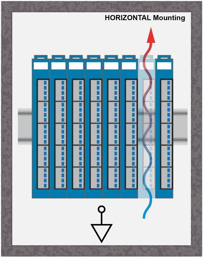
08.09.2020 Page 35SCP 011 S-DIAS SAFETY CPU MODULE 9 Mounting The S-DIAS modules are designed for installation into the control cabinet. To mount the modules a DIN-rail is required. The DIN rail must establish a conductive connection with the back wall of the control cabinet. The individual S-DIAS modules are mounted on the DIN rail as a block and secured with latches. The modules must be mounted horizontally (module label up) with sufficient clearance between the ventilation slots of the S-DIAS module blocks and nearby components and/or the control cabinet wall. This is necessary for optimal cooling and air circulation, so that proper function up to the maximum operating temperature is ensured. Page 36 08.09.2020
S-DIAS SAFETY CPU MODULE           SCP 011

Recommended minimum distances of the S-DIAS modules to the surrounding components
or control cabinet wall:

a, b, c … distances in mm (inches)

08.09.2020                                                               Page 37
SCP 011               S-DIAS SAFETY CPU MODULE

10 Supported Cycle Times
  10.1 Cycle Times below 1 ms (in µs)

   50    100   125   200   250   500

    x     x     x     x     x     x

x= supported

  10.2 Cycle Times equal to or higher than 1 ms (in ms)

    1     2     3     4     5     6    7    8    9    10   11   12   13   14   15     16

    x     x     x     x     x     x    x    x    x    x    x    x    x    x     x     x

x= supported

   17    18    19    20    21    22    23   24   25   26   27   28   29   30   31     32

    x     x     x     x     x     x    x    x    x    x    x    x    x    x     x     x

x= supported

11 Disposal
For the disposal of the product, the respective guidelines, possibly country-specific, must be
observed and followed.

Page 38                                                                             08.09.2020
S-DIAS SAFETY CPU MODULE SCP 011 12 Hardware Class SCP011 Hardware Class SCP011 for the S-DIAS SCP011 Safety CPU Module This hardware class is used to control the SCP 011 hardware module. More information on the hardware can be found in the module documentation. 08.09.2020 Page 39
SCP 011           S-DIAS SAFETY CPU MODULE

 12.1 General

     ClassState    State     This server shows the actual status of the hardware class.
       DeviceID    State     The device ID of the hardware module is shown in this server.
   FPGAVersion     State     FPGA version of the module in the format 16#XY (e.g. 16#10 = version 1.0).
      Hardware     State     Hardware version of the module in the format 16#XXYY (e.g. 16#0120 =
       Version               version 1.20).
  Serial Number    State     The serial number of the hardware module is shown in this server.
   RetryCounter    State     This server increments when a transfer fails.
      Required    Property   This client is active by default, which means that the S-DIAS hardware module
                             at this position is mandatory for the system and can under no circumstances
                             be disconnected or return an error. Otherwise, the entire hardware
                             deactivated. If the hardware module is missing or removed, an S-DIAS error
                             is triggered. If his client is initialized with 0, the hardware module located in
                             this position is not mandatory. This means that it doesn't have to be available
                             or error-free. However, which components identified as "not required" should
                             be selected with regard to the safety of the system.

Page 40                                                                                          08.09.2020
S-DIAS SAFETY CPU MODULE SCP 011
12.2 Safety
Safety State State Status of the Safety module.
Possible Statuses and their meaning:
_ModuleNotFound The module was not found at the set position.
_SafetyClassOK The module was located and initialized
without error.
_MemAllocFailed An attempt to allocate memory for the module
has failed.
_ReadFWVerFailed The module's firmware could not be read.
_ReinitConfig The configuration in the CPU has changed
and the hardware classes are now being
updated.
_ModFromCfgNotFound A module from the configuration is not
physically available, its hardware class has
been placed however.
A module from the configuration is not
physically available and its hardware class
has not been placed.
A module from the configuration is not a C-
DIAS module (according to its HW path).
_UnsafeVarNotFound An unsafe variable cannot be found in the
project. Compare the syntax in the
SafetyDesigner and the project.
_UnknownCfgError An error has occurred while reading the
configuration or when creating the routing
tables.
_AsyncComError Several sequential asynchronous
commands failed. Please contact Sigmatek
support
_DOsIncreasedRestartAp The number or sized of the module access
p was increased with a new Safety project. =>
The application must be restarted, because
the new data is not covered by the current
access.
_LostPowerSupply The CPU supply has failed.
_WrongSafetyHW The placed Safety modules in the project do
not match the actual modules.
For each physical module, a Safety object
must be placed in the project.
Run State State Shows whether the module is in operational mode.
0 Operational mode inactive
1 Operational or temporary operational mode active
State Shows the operating status of the module.
Service Mode 0 Operational Mode
1 Service Mode
2 "Check Configuration" Phase active
08.09.2020 Page 41SCP 011 S-DIAS SAFETY CPU MODULE
Error State State Indicates whether the module has detected an error.
0 No error detected
1 Error detected
2 Transfer timeout for data needed by another module
Quit State If the safety.dlm is used, other errors (server error = 1) can be cancelled
Communication starting with dlm version 6.
Errors
Caution!
Cancellation can activate Safety outputs and thereby lead to unexpected
responses from machine elements.
If this function is provided through the visualization, a corresponding warning
should be displayed.
The server shows the current cancellation satus:
2 Busy canceling error
1 Busy canceling communication error
0 Ready
-1 Error creating Safety statement via dlm
-2 Deactivating user input request failed
-3 Module selection via Safety number failed
-4 Connecting to the module failed (the SafetyDesigner cannot be
online while canceling errors!)
-5 Canceling error in the module failed
-6 Removing the Safety statement via dlm failed
Firmware State In this server, the Firmware version of the hardware used is displayed in xx.yy
Version format. Whereby x represents the major version and y the minor version.
For example, 16#0100 means v1.0
Safety Number State Shows the unique Safety number of the module.
Safety Retry State This server shows the current number of retries of the Safety bus.
Counter
Designer State Shows the CRC of the SafetyDesigner project configuration.
Project Config This can be compared with the CRC of that displayed in the SafetyDesigner
CRC when printing the project (or in the print preview).
Designer State Name of the Safety Designer project
Project Name
Designer State Revision number of the Safety Designer project
Project
Revision
Validaten State Shows the status of the validation button.
Button State 0 Validation button not used at the moment
1 Now the desired command can be selected by pressing the
button
2 Command is executed
3 Error in module
Fast Unsafe Output Bit field with 32 fast non-Safe inputs. If the client ActivateFastUnsafeIOs = 1,
Inputs the fast non-Safety inputs in the SafetyDesigner (right click on "Unsafe
input(s)" => "Create Fast Unsafe Variable" in the variable tree) are read by
this server and transported to the module.
Page 42 08.09.2020S-DIAS SAFETY CPU MODULE SCP 011
Fast Unsafe Input Bit field with 32 non-Safe outputs. If the client ActivateFastUnsafeIOs = 1, the
Outputs fast non-Safety outputs in the Safety Designer (right click on "Unsafe
output(s)" => "Create Fast Unsafe Variable" in the variable tree) are read from
the module and displayed in the server.
Server Update Property Time interval in ms, in which the server (unsafe variables in the Safety
Time Designer) should be updated.
The Client is updated automatically when the time setting is too short for the
number of available servers.
SPDO Read Property The maximum size of the safe read PDO data can be entered for a precise
Size resources calculation in the HW Editor.
The exact size can be read in the SafetyDesigner. Simply right click on the
project -> Show PDO length of modules and the PDO lengths of the Safety
CPUs are displayed.
The number of bytes in the column "SPDO Read Size" is the number to be
entered for "SPDO Read Size".
Default value: 28
SPDO Write Property The maximum size of the safe write PDO data can be entered for a precise
Size resources calculation in the HW Editor.
The exact size can be read in the SafetyDesigner. Simply right click on the
project -> Show PDO length of modules and the PDO lengths of the Safety
CPUs are displayed.
The number of bytes in the column "SPDO Read Size" is the number to be
entered for "SPDO Read Size".
Default value: 28
Additional Write Property The number of additional write PDO accesses per cycle can be entered for a
PDOs precise resources calculation in the HW Editor.
The exact size can be read in the SafetyDesigner. Simply right click on the
project -> Show PDO length of modules.
In the dialog the column "Number of PDO frames per bus cycle" shows the
number of PDO frames per cycle for the respective CPU.
This number minus 1 is then the number to be entered for "Additional Write
PDOs". E.g.: Number of PDO frames per bus cycle = 3 -> Additional Write
PDOs = 2
Default value: 0
12.3 Communication Interfaces
ALARM Downlink With this downlink the corresponding alarm class can be placed via the
hardware editor.
08.09.2020 Page 43SCP 011 S-DIAS SAFETY CPU MODULE
12.4 Global Methods
12.4.1 FetchDiagState
This method is used to read the diagnostic status information (Run State, Config State, Login
Level, Error Counter IO State) from The Safety CPU.
12.4.2 GetDiagState
This method is used to retrieve the read diagnostic information of the class.
Transfer parameters Type Description
pDiagState ^SafetyDiagState Pointer to the structure in which the diagnostic data should
be provided.
Return parameters Type Description
StateReady BOOL FALSE Status is not yet ready (values from input
parameter has not changed).
TRUE Status is ready
12.4.3 FetchDiagInfo
This method is used to read the diagnostic status information (Controller ID, Act Error Code,
First Error Code, Reason Code 0 und 1) from the Safety CPU.
Transfer parameters Type Description
ucChoice USINT Selection of the micro controller from which the diagnostic
information should be read.
12.4.4 GetDiagInfo
This method is used to retrieve the read diagnostic information of the class.
Transfer parameters Type Description
pDiagInfo ^SafetyDiagInfo Pointer to the structure in which the diagnostic data should
be provided.
Return parameters Type Description
StateReady BOOL FALSE No new data available
TRUE New data available
Page 44 08.09.2020S-DIAS SAFETY CPU MODULE SCP 011
12.4.5 SaveLog
This method can be used to store the log file from one of the two micro controllers This is a
binary file and should be sent to SIGMATEK support when an error occurs)
Transfer parameters Type Description
ucChoice USINT Micro controller selection
0 µC1
≠0 µC2
pDPNE ^CHAR Here, the pointer to there log file name is sent.
Return parameters Type Description
Success BOOL FALSE Error during start, another process stored in
the log file is currently active.
TRUE Start successful, log file is stored.
12.4.6 SaveLogActive
This method returns whether or not a log file is stored.
Return parameters Type Description
InProgress BOOL FALSE Currently no log file is backed up.
TRUE A log file is currently being backed up.
12.5 Internal units
To cancel general errors, the safety.dlm file must be located in the "C:\LSLSYS\" directory
and in the AUTOEXEC.LSL file, the following line must be added: LOADSAFETY
Note: When using a SALAMANDER system, these steps are not required, since the function
is already integrated into the OS.
08.09.2020 Page 45SCP 011 S-DIAS SAFETY CPU MODULE
Documentation Changes
Change date Affected Chapter Note
page(s)
11.02.2014 12 5 Connector Layout Changed image
14 5.2 Applicable Connectors Connection capacity added
French notes added
01.04.2014 29 10 Mounting Text updated
29.04.2014 1 New photo
11 3.2 Electrical Requirements Changed table content and added notice below
23.05.2014 10 2.3 Compatibility Added chapter
18.07.2014 14 5 Connector Layout Added wiring notice
08.09.2014 11 3.2 Electrical Requirements Added Supply voltage (UL) and notice in grey box
12 3.3 Miscellaneous Added Standard
12.01.2015 10 2.3 Expanded Compatibility description
30.01.2015 27 9 Wiring Guidelines Added note concerning connecting the S-DIAS
module while voltage is applied
26.03.2015 16 5.2 Applicable Connectors Added connections
07.05.2015 New writing: EN ISO 13849-1/-2
18.05.2015 12 3.4 Environmental Conditions Expanded vibration resistance
08.06.2015 1 Text: Safe IO => modules added
08.07.2015 11 3.2 Electrical Requirements Added mnemotechnic verse
04.08.2015 Info Cover Translation from German added
15.10.2015 9, 10 3.2 Electrical Requirements Table split
20.01.2016 11 3.2 Electrical Requirements Updated
11.03.2016 11 3.2 Electrical Requirements Note Safety error added
28.04.2016 32 10 Mounting Graphics distances
27.06.2016 CAN -> Safety Interface
17.08.2017 14 3.4 Environmental Conditions Pollution Degree
18 5.2 Applicable Connectors Sleeve length added
Added info regarding ultrasonically welded strands
Page 46 08.09.2020S-DIAS SAFETY CPU MODULE SCP 011
18.10.2017 19 5.3 Label Field Added chapter
33 10 Mounting Graphic replaced
19.06.2018 12 3.2.1 Module Supply Note UL conditions
20.09.2018 5 Connector Layout Note added
02.04.2019 10 2.3 Safety-Relevant Correction of the safety-relevant parameters
Parameters
16 3.4 Environmental Conditions Corrections environmental conditions
all Corrections due to CE
01.10.2019 13 3.2.2 S-DIAS Bus/Safety Footnote 4 updated
Supply
14.11.2019 10 Supported Cycle Times Chapter added
02.12.2019 2.3 Safety-Relevant Values updated
Parameters
28.02.2020 36 10 Supported Cycle Times Text adapted
20.07.2020 all Up to 60 °C ambient temperature
02.09.2020 16 3.2.2 S-DIAS Bus/Safety For footnote (5) text “horizontal mounting position
Supply (Output) and” removed
08.09.2020 39 12 Hardware Class SCP011 Chapter added
08.09.2020 Page 47SCP 011 S-DIAS SAFETY CPU MODULE Page 48 08.09.2020
Vous pouvez aussi lire