SNC 021 S-DIAS Safety Incremental Encoder - Sigmatek
←
→
Transcription du contenu de la page
Si votre navigateur ne rend pas la page correctement, lisez s'il vous plaît le contenu de la page ci-dessous
SNC 021
 S-DIAS Safety
 Incremental Encoder

Date of creation: 14.11.2017 Version date: 08.08.2019 Article number: 20-896-021-E
Publisher: SIGMATEK GmbH & Co KG
 A-5112 Lamprechtshausen
 Tel.: +43/6274/4321
 Fax : +43/6274/4321-18
 Email: office@sigmatek.at
 WWW.SIGMATEK-AUTOMATION.COM

 Copyright © 2017
 SIGMATEK GmbH & Co KG

 Translation from German

All rights reserved. No part of this work may be reproduced, edited using an electronic system, duplicated or
distributed in any form (print, photocopy, microfilm or in any other process) without the express permission.

We reserve the right to make changes in the content without notice. The SIGMATEK GmbH & Co KG is not responsible
for technical or printing errors in the handbook and assumes no responsibility for damages that occur through use
of this handbook.
S-DIAS SAFETY SNC INCREMENTAL ENCODER SNC 021

S-DIAS Safety SNC Incremental Encoder SNC 021

The S-DIAS Safety SNC incremental encoder module SNC 021 provides
the values of two incremental encoders, the Safety CPU as well as the non-
Safe CPU (standard PLC).

The two-channel safety function "monitors" the increments in the
incremental encoder interfaces and processes the so-called Safety core in
two micro controllers with cross-communication.

The incremental encoder function is monitored through a 2-channel
analysis of the encoder signals, with 2-channel error detection of each data
line, as well as via the measurement of the encoder supply voltages and
currents.

Speed, position, direction and acceleration are monitored via the Safe
application in the Safety CPU.

The module detects various error types, such as a cable break, cross-circuit
and inverted input signals.

The safety functions of the component meet

• for two-channel application
 the requirements for SIL 3 or SIL CL 3 in accordance with EN / IEC 62061 and PL e,
 Cat. 4 in accordance with EN ISO 13849-1/-2

as well as

• for one-channel application,
 the requirements for SIL 2 or SIL CL 2 in accordance with EN / IEC 62061 and PL d,
 Cat. 2 in accordance with EN ISO 13849-1/-2.

08.08.2019 Page 1
SNC 021 S-DIAS SAFETY SNC INCREMENTAL ENCODER

Contents
1 Basic Safety Guidelines .......................................................... 4
 1.1 General Safety Information .......................................................... 4

 1.2 Further Safety Guidelines ............................................................ 5

 1.3 General Requirements ................................................................. 6

2 Conformity with EU Guidelines ............................................ 11
 2.1 Functional Safety Standards ..................................................... 11

 2.2 EU Conformity Declaration ........................................................ 11

 2.3 Safety-Relevant Parameters ...................................................... 12

 2.4 Compatibility ............................................................................... 12

3 Technical Data ....................................................................... 13
 3.1 I-encoder Specifications ............................................................ 13

 3.2 Electrical Requirements ............................................................. 13

 3.3 Miscellaneous ............................................................................. 15

 3.4 Environmental Conditions ......................................................... 15

4 Mechanical Dimensions ........................................................ 16

5 Connector Layout .................................................................. 17
 5.1 Status LEDs ................................................................................. 18

 5.2 Applicable Connectors ............................................................... 19

 5.3 Label Field ................................................................................... 20

6 Wiring ..................................................................................... 21

Page 2 08.08.2019
S-DIAS SAFETY SNC INCREMENTAL ENCODER SNC 021

 6.1 Wiring Example ........................................................................... 21

 6.2 Note .............................................................................................. 22

7 RS422 Interface ..................................................................... 22

8 Mounting ................................................................................ 23

9 Disposal ................................................................................. 24

10 Encoder Configuration ......................................................... 25

11 Installing the Encoder ........................................................... 27

12 Important Notes for Two-channel Application .................... 28

08.08.2019 Page 3
SNC 021 S-DIAS SAFETY SNC INCREMENTAL ENCODER

1 Basic Safety Guidelines
1.1 General Safety Information

Non-compliance with the Safety guidelines can result in danger to personnel, which could
then lead to serious injury or in worst cases, death. In less serious cases, systems and
equipment can be damaged.

The following symbols identify the individual risks as well as the degree of seriousness; their
respective meanings are briefly explained below. You should therefore familiarize yourself
with the Safety symbols and their meanings to prevent dangers and risks.

 DANGER DANGER
 Identifies an immediate danger with high risk, which
 can lead to immediate death or serious injury if not
 avoided.
 Indique un danger direct à haut risque d’un décès
 immédiat ou des blessures graves si les consignes de
 sécurité ne sont pas respectées.

 WARNING WARNING

 Identifies a possible danger with a mid-level risk, which
 can lead to death or (serious) injury if not avoided.

 Indique un danger possible d’un risque moyen de
 décès ou de (graves) blessures si les consignes de
 sécurité ne sont pas respectées.

 CAUTION CAUTION
 Identifies a low risk danger, which can lead to injury or
 property damage if not avoided.
 Indique un danger avec un niveau de risque faible des
 blessures légères ou des dommages matériels si les
 consignes de sécurité ne sont pas respectées.

Page 4 08.08.2019
S-DIAS SAFETY SNC INCREMENTAL ENCODER SNC 021

1.2 Further Safety Guidelines

 Warning, dangerous electrical voltage
 Avertissement d’une tension électrique dangereuse

 Hot surface warning
 Avertissement d’une surface chaude

 Danger for ESD-sensitive components

 This symbol identifies important or additional
 information regarding the operation of the safety
 modules.
 Ce symbole indique des informations importantes ou
 supplémentaires concernant le fonctionnement des
 modules de sécurité particuliers.

08.08.2019 Page 5
SNC 021 S-DIAS SAFETY SNC INCREMENTAL ENCODER

1.3 General Requirements

Technical This technical documentation is a component of this product.
Documentation
 • This document must be accessible near the machine,
 since it contains important instructions.
 • The technical documentation should be included in the
 sale, rental or transfer of the product.

 Documentation technique

 Cette documentation technique fait partie intégrale du produit.

 • Gardez la toujours à portée de main et à la proximité de
 la machine, car elle contient des informations
 importantes.
 • Distribuez la documentation technique aux secteurs de
 la vente et/ou de la location du produit.

Page 6 08.08.2019
S-DIAS SAFETY SNC INCREMENTAL ENCODER SNC 021

Acceptance of Safety Before handling the product to which this documentation
Guidelines belongs, the operating instructions and safety guidelines must be
 read. SIGMATEK GmbH & Co KG accepts no liability for
 damages resulting from non-compliance with the Safety
 guidelines or applicable regulations.

 Acceptance of the Safety guidelines and the explanations in this
 document, as well as the Safety System Handbook (see
 homepage1) are a basic requirement for proper use. Therefore,
 read this operating manual thoroughly and familiarize yourself
 with each of them in detail.
 More information on standards and regulations etc. can be found
 in the system handbook.

 Prendre connaissance de consignes de sécurité

 Avant toute manipulation on doit impérativement prendre
 connaissance de consignes de sécurité et du mode d’emploi.
 SIGMATEK GmbH & Co KG n'assume aucune responsabilité
 pour les dommages causés par le non-respect des consignes de
 sécurité ou du mode d’emploi respectif.

 La connaissance de consignes de sécurité et le contenu de cette
 documentation ainsi que le mode d’emploi du système de
 sécurité constitue une condition préalable à l'utilisation prévue.
 Lisez ce mode d’emploi et assurez-vous de le comprendre
 jusqu’aux détails.
 Pour plus d'informations sur les normes et les lignes directrices,
 etc., reportez-vous au mode d’emploi

1 Using the search function with the keyword “Safety System Handbook”
08.08.2019 Page 7
SNC 021 S-DIAS SAFETY SNC INCREMENTAL ENCODER

Qualified Personnel Installation, assembly, programming and initial start-up,
 operation, maintenance and decommissioning of control and
 automation technology products in general, as well as safe
 products in particular, can only be performed by qualified
 personnel.

 Qualified personnel in this context are people, who have
 completed training or have trained under supervision of qualified
 personnel and have been authorized to operate and maintain
 equipment of functional safety, systems and facilities in
 compliance with the strict guidelines and standards of Safety
 technology.

 Personnel qualifié

 Installation, montage, programmation, mise en service,
 l'exploitation, l'entretien et mise hors service de produits de
 commande et d'automatisation en général, et de produits liés à
 la sécurité, en particulier, ne peut être effectuée que par le
 personnel qualifié.
 On entend sous terme personnel qualifié les personnes ayant
 acquis une formation professionnelle dispensé par un spécialiste
 sur l’utilisation et surveillance des composants et des systèmes
 de sécurité, ceci conformément aux lignes directrices et les
 normes en vigueur.

Page 8 08.08.2019
S-DIAS SAFETY SNC INCREMENTAL ENCODER SNC 021

Designated Use The Safety modules are designed for use in applications with a
 requirement of functional safety and meet the required conditions
 for Safe operation with the parameters specified in section 2.

 For your own safety and the safety of others, use Safety modules
 for their designated purpose only. Correct EMC installation as
 well as proper transport and storage are also included under
 designated use.

 Non-designated use consists of:
 • any change made to the Safety modules of any kind.
 • the use of damaged Safety modules.
 • the use of the Safety module inconsistent with the
 instructions described in this handbook.
 • The use of the safety module inconsistent with the
 technical data described in this handbook.

 Les modules de sécurité sont conçus pour une utilisation dans
 les applications sollicitant un niveau de sécurité et répondent à
 toutes les conditions nécessaires pour un fonctionnement sûr
 conformément au niveau de performance e (PL e) selon la norme
 EN ISO 13849-1/-2 et SIL 3 ou SIL CL 3 de la norme EN 62061.

 Utilisation prévue

 Utilisez le module de sécurité conformément à son mode
 d’emploi pour votre propre sécurité et celle d'autres personnes.
 L'utilisation conforme comprend également une installation
 conforme CEM ainsi que le transport et le stockage conforme.

 L'utilisation abusive comprend entre autres:

 • Les modifications quelconques apportées aux modules
 de sécurité.
 • Utilisation de modules de sécurité endommagés.
 • Utilisation de modules de sécurité en dehors du cadre
 décrit dans ce mode d’emploi.
 • Utilisation de modules de sécurité en dehors des
 spécifications décrites dans ce mode d’emploi.

08.08.2019 Page 9
SNC 021 S-DIAS SAFETY SNC INCREMENTAL ENCODER

Operator Due Diligence The operator must ensure that
 • the Safety modules are to be used for their designated
 purpose only.
 • the Safety modules are to be operated in error-free, fully
 functional condition only.
 • only sufficiently qualified and authorized personnel
 operate the Safety modules.
 This documentation is complete and in readable condition and
 available at the site of operation.

 Obligation de diligence

 L’utilisateur doit s'assurer que
 • les modules de sécurité ne sont utilisés que selon les
 spécifications.
 • uniquement les modules de sécurité en parfait état de
 fonctionnement peuvent être utilisés.
 • seulement le personnel qualifié et autorisé puisse
 manipuler les modules de sécurité.
 la documentation dans son intégralité et dans un état lisible est
 mise à disposition à l’endroit où les modules de sécurité sont
 utilisés.

Page 10 08.08.2019
S-DIAS SAFETY SNC INCREMENTAL ENCODER SNC 021

2 Conformity with EU Guidelines
2.1 Functional Safety Standards
 - EN / IEC 62061:2005/A2:2015
 - EN ISO 13849-1:2015
 - EN ISO 13849-2:2012

2.2 EU Conformity Declaration

 CE Declaration of Conformity
 The SNC 021 complies with European norms for programmable logic
 controls.
 • 2006/42/EG “Directive of the European Parliament and of the
 Council of 17 May 2006 on Machinery and Change to the Directive
 95/16/EC” (machine guideline)
 • 2014/30/EU “Electromagnetic Compatibility” (EMC guideline)
 • 2011/65/EU Restricted use of certain hazardous substances in
 electrical and electronic equipment (RoHS Guideline)
 The EU Conformity Declarations are provided on the SIGMATEK website.
 Using the search function with the keyword “EU Declaration of Conformity”.

08.08.2019 Page 11
SNC 021 S-DIAS SAFETY SNC INCREMENTAL ENCODER

2.3 Safety-Relevant Parameters

 2-channel application 1-channel application

 Input Module Safety parameters for two Safety parameters for one
 connected incremental encoders, connected incremental encoder, which
 which monitor one another in the SNC is monitored
 021 in the SNC 021

 SNC 021 PFHD = 3.63E-09 (1/h) PFHD =3.61E-09 (1/h)

 including CPU modules MTTFD = 557 years MTTFD = 759 years
 SCP 011/SCP 111
 DC = 99.00 % DC = 97.83 %

 SFF = 99.63 % SFF = 99.56 %

 PL e / CAT 4 according to EN/ISO 13849 PL d / CAT 2 according to EN/ISO 13849

 SIL 3 resp. SIL CL 3 according to EN SIL 2 bzw. SIL CL 2 according to EN
 62061 62061

 The application for a specific PL, These safety parameters were calculated
 category or SIL-CL requires a risk for the SNC 021 when used with a
 analysis of the end-use application to incremental encoder. The safety
 determine whether two incremental parameters of the entire machine must
 encoders are sufficient. be determined in the end application.

 1-channel and 2-channel application:
 The application for a specific PL, category or SIL-CL requires a correct
 installation. Please note any normative requirements of the end application
 (machine) for installation and selection of encoders.

 The use of the specified parameters requires a risk analysis of the end
 application, by which whether 2 incremental encoders is sufficient must be
 determined.

 For two-channel application, both incremental encoders must be monitored in
 the application (SCP 011/111).

2.4 Compatibility

 Compatibility
 For compatibility of the S-DIAS Safety modules, see chapter "Compatibility of
 S-DIAS Safety Modules" in the system handbook.

Page 12 08.08.2019
S-DIAS SAFETY SNC INCREMENTAL ENCODER SNC 021

3 Technical Data
3.1 I-encoder Specifications

 Number of channels 2

 Encoder Incremental encoder with RS422 Interface with null position trace.

 Input frequency 0.75 MHz

 Counter frequency 3 MHz

 Signal analysis 4x

 Encoder resolution maximum 16 bits

 Encoder power supply +5 V supply, short-circuit proof with monitoring function
 and current measurement (+5 V is generated from +24 V at X3)

 Status LED yes

 I-encoder current consumption maximum 300 mA per encoder

3.2 Electrical Requirements

 Supply voltage for the encoder +18-30 V
 supply

 Current consumption of supply typically 162 mA/24 V maximum 200 mA/30 V
 voltage for the encoder supply

 Voltage supply from Safety bus +12 V

 Current consumption on the typically 75 mA maximum 90 mA
 Safety bus (+12 V supply)

 Voltage supply from S-DIAS bus +24 V

 Current consumption on the typically 33 mA maximum 40 mA
 S-DIAS bus (+24 V supply)

08.08.2019 Page 13
SNC 021 S-DIAS SAFETY SNC INCREMENTAL ENCODER

If this S-DIAS Safety module is connected to an SCP with several modules, the total
current of the S-DIAS Safety modules used must be determined and checked.

 The total current of the +24 V supply cannot exceed 800 mA.
 The total current of the +12 V supply cannot exceed 800 mA.

 Si ce module de sécurité S-DIAS Safety est raccordé à un SCP avec plusieurs
modules, le courant total des modules de sécurité S-DIAS utilisés doit être déterminé
 et vérifié.
 Le courant total de l'alimentation +24 V ne peut pas dépasser 800 mA.
 Le courant total de l'alimentation +12 V ne peut pas dépasser 800 mA.

 The SNC 021 module can only be used in conjunction with an
 SCP 011/SCP 111 that has been configured as a master CPU.

 Le module SNC 021 ne peut être utilisé qu'en combinaison avec un module
 SCP 011/SCP 111 lequel a été configuré comme processeur maître.

Page 14 08.08.2019
S-DIAS SAFETY SNC INCREMENTAL ENCODER SNC 021

3.3 Miscellaneous

 Article number 20-896-021

 Hardware version 2.x-3.x

 Standard Two-channel application: EN 62061SIL 3 or SIL CL 3
 EN ISO 13849-1 PL e/Cat. 4

 One-channel application: EN 62061 SIL 2 or SIL CL 2
 EN ISO 13849-1 PL d/Cat. 2

 UL 508 (E247993)

 Approvals CE, CULUS

3.4 Environmental Conditions

 Storage temperature -20 ... +85 °C

 Environmental temperature 0 ... +50 °C

 Humidity 0-95 %, non-condensing

 Installation altitude above sea 0-2000 m without derating
 level
 > 2000 m with derating of the maximum environmental temperature by 0.5
 °C per 100 m

 Operating conditions Pollution degree

 EMC resistance in accordance with 61000-6-7:2015 (Generic standards - Immunity
 requirements for equipment intended to perform functions in safety-related
 systems (functional safety) at industrial locations)

 in accordance with EN 61000-6-2:2007 (industrial area)
 (increased requirements in accordance with IEC 62061)

 EMC noise generation in accordance with EN 61000-6-4:2007 (industrial area)

 Vibration resistance EN 60068-2-6 3.5 mm from 5-8.4 Hz
 1 g from 8.4-150 Hz

 Shock resistance EN 60068-2-27 15 g

 Protection type EN 60529 IP20

08.08.2019 Page 15
SNC 021 S-DIAS SAFETY SNC INCREMENTAL ENCODER

4 Mechanical Dimensions

Page 16 08.08.2019
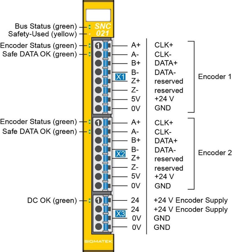
S-DIAS SAFETY SNC INCREMENTAL ENCODER SNC 021

5 Connector Layout

The connections of the +24 V supply (X3: pin 1 and pin 2) or the GND supply (X3: pin
 3 and pin 4) are internally bridged. To supply the module, only one connection to a
 +24 V pin (pin 1 or pin 2) and a GND pin (pin 3 or pin 4) is required. The bridged
 connections may be used for further looping of the +24 V supply and the GND
 supply. However, it must be taken into account that a total current of 6 A per
 connection is not exceeded by the forward looping!

08.08.2019 Page 17
SNC 021 S-DIAS SAFETY SNC INCREMENTAL ENCODER

5.1 Status LEDs

 Bus Status green ON bus communication OK

 OFF no supply available

 BLINKING (5 Hz) no communication

 Safety Used yellow ON can be set from the application

 OFF (e.g. the module LED can be set to blinking through the
 visualization so that the module is easily found in the control
 BLINKING (2 Hz) cabinet)

 BLINKING (4 Hz)

 Encoder Status green ON encoder signal OK

 OFF encoder is not in use

 BLINKS signal error was detected

 Safe Status green ON Safety of the Safe CPU provides invalid encoder values

 OFF encoder is not in use or

 Safety provides invalid encoder values

 DC OK green ON +24 V input voltage for encoder supply OK

Page 18 08.08.2019
S-DIAS SAFETY SNC INCREMENTAL ENCODER SNC 021

5.2 Applicable Connectors
Connectors:
X1-X3: Connectors with spring terminals (included in delivery).
The spring terminals are suited for the connection of ultrasonically compacted (ultrasonically
welded) wires.

Connections:
 Stripping length/sleeve length. 10 mm
 Mating direction: parallel to the conductor axis or circuit board
 Conductor cross section rigid: 0.2-1.5 mm2
 Conductor cross section flexible: 0.2-1.5 mm2
 conductor cross section strands ultrasonically compacted: 0.2-1.5 mm2
 Conductor cross section AWG/kcmil: 24-16
 Conductor cross section flexible with ferrule without plastic 0.25-1.5 mm2
 sleeve:
 Conductor cross section flexible with ferrule with plastic sleeve: 0.25-0.75 mm2 (reason for reduction d2 of the
 ferrule)

08.08.2019 Page 19
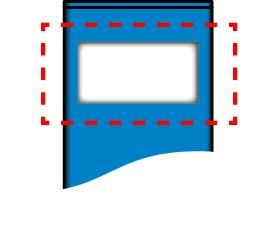
SNC 021 S-DIAS SAFETY SNC INCREMENTAL ENCODER

5.3 Label Field

 Manufacturer: Weidmüller

 Type: MF 10/5 CABUR MC NE WS

 Article number Weidmüller 1854510000

 Compatible printer Weidmüller

 Type: Printjet Advanced 230V

 Article number Weidmüller 1324380000

Page 20 08.08.2019
S-DIAS SAFETY SNC INCREMENTAL ENCODER SNC 021

6 Wiring
6.1 Wiring Example

08.08.2019 Page 21
SNC 021 S-DIAS SAFETY SNC INCREMENTAL ENCODER

6.2 Note

The input filters, which suppress noise signals, allow operation in harsh environmental
conditions. A careful wiring method is also recommended to ensure error-free function.

The following installation guidelines should be observed:

• Avoid parallel connections between input lines and load-bearing circuits.

• Protective circuits for all relays (RC networks or free-wheeling diodes)

• Correct wiring to ground

 The ground bus should be connected to the control cabinet when possible!

 Si possible la terre doit être connectée à l'armoire de commande!

 Wiring and mounting must be performed with no voltage applied!

 IMPORTANT:
 The S-DIAS module CANNOT be connected/disconnected while voltage is applied!

 Important!
 Le module S-DIAS ne peut pas être inséré ou retiré sous tension.

7 RS422 Interface

The RS422 interface is internally connected in the component.

Page 22 08.08.2019
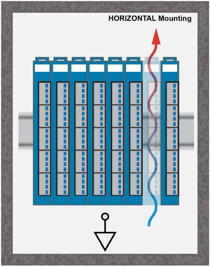
S-DIAS SAFETY SNC INCREMENTAL ENCODER SNC 021

8 Mounting

The S-DIAS modules are designed for installation into the control cabinet. To mount the
modules a DIN-rail is required. The DIN rail must establish a conductive connection with the
back wall of the control cabinet. The individual S-DIAS modules are mounted on the DIN rail
as a block and secured with latches. The modules must be mounted horizontally (module
label up) with sufficient clearance between the ventilation slots of the S-DIAS module blocks
and nearby components and/or the control cabinet wall. This is necessary for optimal cooling
and air circulation, so that proper function up to the maximum operating temperature is
ensured.

08.08.2019 Page 23
SNC 021 S-DIAS SAFETY SNC INCREMENTAL ENCODER

Recommended minimum distances of the S-DIAS modules to the surrounding components
or control cabinet wall:

a, b, c … distances in mm (inches)

9 Disposal
For the disposal of the product, the respective guidelines, possibly country-specific, must be
observed and followed.

Page 24 08.08.2019
S-DIAS SAFETY SNC INCREMENTAL ENCODER SNC 021

10 Encoder Configuration
The maximum encoder frequency is defined with 750 kHz (at 1x edge analysis). This
corresponds to a maximum counter frequency or 1.5 MHz (at 4x edge analysis).

When selecting the encoder to install, this must be taken into consideration accordingly.

In the following table, the permissible speed in the rotary encoder for the respective
resolution based on the maximum encoder frequency can be seen.

 Encoder Resolution Speed Scaling
 (Increments/Conversion) Revolutions/Second Revolutions/Minute

 60 12.500 750.000

 80 9.375 562.500

 100 7.500 450.000

 128 5.859 351.563

 150 5.000 300.000

 200 3.750 225.000

 256 2.930 175.781

 512 1.465 87.891

 1024 732 43.945

 2048 366 21.973

 4096 183 10.986

This is only a sample of possible encoder resolutions.

With the following formulas, the highest permissible rotation speed (revolutions/min) can be
determined for an encoder with a resolution that is not listed in the table above.

Revolutions/sec:

 =

Revolutions/min:
 ∗ 60
 =

08.08.2019 Page 25
SNC 021 S-DIAS SAFETY SNC INCREMENTAL ENCODER

Legend:
nmax … highest permissible speed in revolutions/sec or revolutions/min.
fmax … maximum encoder frequency of 750 kHz
res … encoder resolution according to the manufacturer data sheet.

If linear encoders are used or for example, a translation ratio must be included, as well as the
calculation for the maximum permissible speeds and the scaling parameters that must be
defined in the Safety Designer for each encoder, taken into consideration.
The following formula is thereby generated:

 = ( ∗ ⁄ ) ∗ ( ⁄ )

Legend:
vmax … maximal possible, scaled speed
fmax … maximum encoder frequency of 750 kHz
mulposition… factor for converting the position of length (units parameter)
divposition … divisor for converting the position of length (units parameter)
mulspeed … factor for converting the speed or time base (speed multiplier parameter)
divspeed … divisor for converting the speed or time base (speed divisor parameter)

Due to the 32-bit data width, a maximum value of 2,147,483,647 is generated for the upper
speed limit (the highest bit is used as the sign).
The following conditions result:

 ≤ 2,147,483,647 ≤
 ≤ 2,147,483,647 ≤

Legend:
f … Encoder frequency (with simple edge analysis)

Notes on position monitoring

If the encoder is set for position monitoring, (linear, rotation encoder), it must be taken into
consideration that the minimum and maximum value of the position must be monitored in the
application. The maximum value is dependent on the scaling parameters for calculating the
parameters and limited to 32 bits.

Page 26 08.08.2019
S-DIAS SAFETY SNC INCREMENTAL ENCODER SNC 021

11 Installing the Encoder
Line and encoder errors are diagnosed using, among other things, the measurement of the
encoder currents.
For this purpose, the preset values for measuring current must be defined in the system. The
current limits are defined in the automatic system automatically, so the user does not have to
predefine or configure any additional parameters.

In the unverified status of the system, the encoder currents are measured while starting the
system and used as temporary reference values. Based on the determined reference values,
the current limits are temporarily defined with ±25%. If a corresponding fluctuation in the
encoder currents due to a wiring fault is detected during movement, the system switches to
the Safe mode and the appropriate diagnostic codes are provided.

CAUTION!
Before the Safety system is labeled as verified, the wiring of the installed encoder must be
checked manually to ensure that the system operates error-free (the encoder operates
without fault).

During verification, which is run via the “Set Verified” button in the SafetyDesigner or the
validation button on the Safe CPU, the actual current measurements are used to determine
the permissible limit values for the encoder current and then stored in the Safe CPUs remnant
data. These limit values are based on the measured value ±25 %.

After successful validation, the encoder currents are monitored using the current values
stored in the Safe CPU. When in verified status, the upper or lower limits are exceeded, the
system changes to safe mode and the appropriate diagnostic code for error analysis is again
provided.

In the standard application, the actual and preset current values are provided via the
hardware classes.

CAUTION! Exchanging the encoder
Basically, the Safety system cannot detect an encoder exchange when no power is applied.
The parameters of the new encoder could be different from the replaced encoders with regard
to the currents, whereby it is no longer possible guarantee the appropriate monitoring of the
newly installed encoder.

In such a case, the system must be reverified. This means reconfiguring the Safe CPU via
the SafetyDesigner or µSD card and verifying (see Safety System manual)

08.08.2019 Page 27
SNC 021 S-DIAS SAFETY SNC INCREMENTAL ENCODER

12 Important Notes for Two-channel Application
When using the SNC 021 module in compliance with SIL 3 or SIL CL 3 according to EN
62061 and PL e, Cat. 4 according to EN ISO 13849-1, it must be taken into consideration
that for 2-channel application, a part of the possible wiring errors can only be detected by
comparing the measurement results of both encoders in the Safety application of the Safe
CPU. The inversion of signal lines A+ with A- as well as B+ with B- are one of these errors.
Mechanical errors, such as a detached coupling can also be detected only in the Safety
application of the Safe CPU.

To meet the requirements of the diagnostic coverage ratio, both encoders must be
synchronously monitored in the Safety application of the Safe CPU.

For synchronous monitoring, the functional Safety block SF_SkewMonitor (see chapter
“Numerical Function Blocks” in the SafetyDesigner tool help) must be placed in the Safety
project and used according to the documentation.

The inputs S_ChnValue1 and S_ChnValue2 of the functional Safety blocks must be wired
with the input information _Chn1Value and S_Chn2Value (synchronous monitoring of the
position) or alternatively, with S_Chn1Speed and S_Chn2Speed (synchronous monitoring of
the speed) of the SNC 021 module.

The required tolerance must be defined by the user. During synchronous monitoring via the
position, it must be taken into consideration that if there is the possibility of a position overflow,
the scaling parameter can cause position jumps. In such a case, the scaling parameter for
calculating the position should be left at the default settings (factor and divisor
are 1), or synchronous monitoring performed using the speed.

 If the system is not in Safe mode, synchronous monitoring must be performed
 according to the previously mentioned criteria

Si le système n'est pas en mode Safe, une surveillance synchrone doit être effectuée
 selon les critères mentionnés précédemment.

If all mechanical error sources can be excluded due to the coupling type and the type of
encoder used (e.g. defective encoder mechanics), monitoring the direction of both encoders
is then sufficient.

This can be run in the Safety application using the functional Safety block
SF_DirectionMonitor (see chapter “Numeric Function Blocks” in the SafetyDesigner tools
help) and in this case, performed for both encoders.

 If synchronous monitoring is not performed in the Safety application as described
 here, the machine manufacturer must then prove that the requirements of SIL 3 or
 SIL CL 3 according to EN 62061 and PL e, Cat. 4 according to EN ISO 13849-1/-2 are
 met if required for the machine.

Page 28 08.08.2019
S-DIAS SAFETY SNC INCREMENTAL ENCODER SNC 021

 Si la surveillance synchrone n'est pas effectuée par le logiciel de sécurité comme
 décrit dans la présente documentation, le constructeur de la machine doit alors
prouver que les exigences des normes SIL 3 ou SIL CL 3 selon EN 62061 et PL e, Cat.
 4 selon EN ISO 13849-1/-2 sont respectées si la machine le requiert.

08.08.2019 Page 29
SNC 021 S-DIAS SAFETY SNC INCREMENTAL ENCODER

Documentation Changes

Change date Affected page(s) Chapter Note

20.09.2018 5 Connector Layout Note added

15.11.2018 15 3.3 Miscellaneous UL instead of UL in preparation

19.02.2019 28 11 Installing the Tolerance changed from +25 % to ±25 %
 Encoder

02.04.2019 12 2.3 Safety-Relevant Correction of the safety-relevant parameters
 Parameters

 16 3.4 Environmental Corrections environmental conditions
 Conditions
 all Corrections due to CE

08.08.2019 Entire document “safety-related” replaced

Page 30 08.08.2019
Vous pouvez aussi lire