Technical Instruction - FISBA READYBeamTM Compact multi-wavelength laser source - Fisba.com
←
→
Transcription du contenu de la page
Si votre navigateur ne rend pas la page correctement, lisez s'il vous plaît le contenu de la page ci-dessous
Technical Instruction

FISBA READYBeamTM
Compact multi-wavelength laser source

                                   January 2020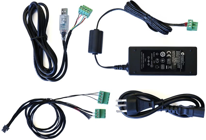
Content

1       Safety                                          4

1.1     Explanation of symbols                          4

1.1.1   General safety instructions                     4

1.1.2   Laser safety                                    4

1.1.3   Laser area                                      4

1.2     Sécurité                                        6

1.2.1   Explication des symboles                        6

1.2.2   Consignes de sécurité générales                 6

1.2.3   Sécurité du laser                               6

1.2.4   Zone laser                                      6

1.3     Warning and information labels                  8

1.4     Correct and specified use of the unit           8

1.5     Warranty conditions                             9

1.5.1   Limits of the warranty                          9

2       Technical system                                9

2.1     Laser module                                    9

2.2     Installation and commissioning                  10

2.2.1 Unpacking and checking for visible damage         10

2.2.2 Installation                                      10

2.2.3 Operating the FISBA READYBeam       TM
                                                        10

2.2.4 Digital operating with the software application   10

2.2.5 Software interface                                11

2.2.6 Analog controlled operation                       11
1 Safety 1.1 Explanation of symbols This symbol is used for all points in these operating instructions to which special attention is to be paid so that all directives, regulations, instructions and the correct work sequence are observed, and to prevent minor or serious damage to the laser system or plant. 1.1.1 General safety instructions The operating instructions and the safety instructions are to be read and observed prior to installation and commissioning! The operating instructions must be read, understood and followed by the operators responsible for the unit. Along with the instructions in these operating instructions, also observe the generally applicable safety and accident prevention regulations! All work on installation and commissioning as well as all maintenance is to be performed by appropriately qualified personnel. National accident prevention regulations, EN and IEC standards are to be observed. Appropriately qualified personnel in the context of these basic safety instructions are persons who are familiar with the fitting, installation, placing in operation and operation of the product and have qualifications appropriate to their task. 1.1.2 Laser safety The unit is a class 3B laser device. Both the direct beam and its reflections from diffuse reflective surfaces are dangerous.The unit emits strong power beams in the visible spectral range (approx. 400 nm to 700 nm, for more detailed information see the data sheet, page 14). The radiation can cause irreversible damage to the eyes if the necessary protective measures are not taken. 1.1.3 Laser area The laser area is the area in which the values for the maximum permissible irradiation can be exceeded. Here the possibility of unintentional deflection of the laser beam is also to be taken into account. If operational equipment other than that given in this manual or another procedure is used, dangerous exposure to the radiation may result. Laser system screened inside a protective cover By using suitable screening it can be ensured that people are not exposed to the laser radiation. In this way the laser class is reduced and it is possible to work with the closed arrangement without additional limitations or further measures. 4
However, in this case the following requirements apply to the protective cover:
·· The protective cover must be appropriate to adequately shield the laser
radiation. It is therefore necessary to use laser safety glass or laser safety
film for viewing windows.
·· The cover itself as well as any doors or flaps in the cover must be protected
using the interlock circuit that automatically shuts down and inhibits the laser
immediately on intentional or unintentional opening.
If the interlock circuit is disabled for service or maintenance work on the system with
the cover open, the laser area is enlarged again and the regulations in the next section
«Presence of persons in the laser area» apply.
Presence of persons in the laser area
In the laser area, people are subject to hazards, in particular ocular. Therefore the
following measures must be taken and the following safety regulations observed:
·· The room must have an emergency exit.
·· The room must be optically screened from the environment (e.g. laser safety
film on the windows).
·· The laser area is to be kept as small as possible, to be bounded by suitable
screening and protected against access by unauthorized persons. The num-
ber of persons in the laser area should be reduced to the minimum.
·· There must be a warning device on all entrances to the room that indicates
the laser radiation hazard.
·· If the entry doors are not protected using the interlock circuits, opening the
doors easily from the outside must be impossible to prevent thoughtless
entry.
·· All persons who are in the laser area during operation must be informed
about the dangers of the laser radiation.
·· Laser safety glasses/goggles must be worn in the laser area. The operating
organisation must ensure that suitable safety glasses/goggles are available.
The glasses/goggles are selected in accordance with DIN EN 207. Please see
the data sheet on the unit for the actual wavelength of your laser. Herein-
after, the term safety glasses is always used to refer to suitable laser safety
glasses/goggles. Caution: in some circumstances your laser safety glasses/
goggles may not protect you from a powerful red pilot beam.
·· There must not be any potentially explosive substances in the laser area.
Easily inflammable substances may catch fire.
·· Glossy reflective equipment must be either removed from the laser area or
covered. Windows and reflecting walls are also to be covered with material
with low inflammability.
51.2 Sécurité 1.2.1 Explication des symboles Dans ce mode d’emploi, ce symbole indique qu’une attention particulière est requise, afin d’observer l’ensemble des directives, réglementations et consignes, ainsi que la séquence de travail correcte pour éviter tous dommages mineurs ou importants au système laser ou à l’installation. 1.2.2 Consignes de sécurité générales Le mode d’emploi et les consignes de sécurité doivent être lus et observés rigou- reusement avant l’installation et la mise en service. Les opérateurs responsables de l’unité doivent lire, comprendre et suivre le mode d’emploi. Outre les consignes de ce mode d’emploi, il convient également d’observer les réglementations relatives à la sécurité et à la prévention des accidents applicables en général. L’installation, la mise en service et l’entretien doivent être réalisés par un personnel qualifié de manière appropriée. Les réglementations nationales concernant la prévention des accidents et les normes EN et CEI doivent être observées. Dans le cadre de ces consignes de sécurité élémentaires, le personnel dûment qualifié désigne des personnes qui ont des connaissances en montage, installation, mise en service et fonctionnement du produit et qui ont les qualifications appropriées. 1.2.3 Sécurité du laser L’unité est un dispositif laser de classe 3B. Le faisceau direct et les réflexions des surfaces réfléchissantes diffuses sont dangereux. L’unité émet des faisceaux de forte puissance dans le domaine spectral invisible, visible et infrarouge (environ 400 nm - 700 nm, voir fiche technique pour en savoir plus, page 14). Le rayonnement peut endommager les yeux de manière irréversible, si les mesures de protection nécessaires ne sont pas correctement appliquées. 1.2.4 Zone laser La zone laser est la zone dans laquelle les valeurs du rayonnement maximum autorisé peuvent être dépassées. La possibilité d’une déviation accidentelle du faisceau laser doit également être prise en compte. Si un autre équipement que celui indiqué dans ce manuel ou une autre procédure est utilisé, une exposition dangereuse au rayonnement peut avoir lieu. 6
Système laser protégé dans une enceinte
Une protection adaptée garantit que les personnes ne sont pas exposées au rayon-
nement laser. Ainsi, la classe du laser est baissée et il est possible de travailler avec la
configuration fermée, sans limitations ou mesures supplémentaires.
Toutefois, dans ce cas, les exigences suivantes s’appliquent à l’enceinte de protection:
·· L’enceinte de protection doit être adaptée de sorte à enfermer correctement
le rayonnement laser. Il est donc nécessaire d’utiliser un verre ou un film de
sécurité laser pour les fenêtres.
·· L’enceinte, ainsi que les portes ou volets doivent être équipés d’un circuit
de verrouillage, qui éteint automatiquement le laser, en cas d’ouverture
volontaire ou non.
Si le circuit de verrouillage est désactivé pour l’entretien ou la maintenance du systè-
me avec l’enceinte ouverte, la zone laser est élargie et les instructions de la section
suivante «Présence de personnes dans la zone laser» s’appliquent.
Présence de personnes dans la zone laser
Toute personne se trouvant dans la zone laser s’expose à des risques, notamment
oculaires. Il convient donc de prendre les mesures nécessaires suivantes et d’ob
server les dispositions de sécurité qui suivent:
·· La pièce doit avoir une issue de secours.
·· La pièce doit être protégée (p. ex. film de sécurité laser sur les fenêtres).
·· La zone laser doit être réduite au minimum, délimitée par une protection
adaptée et protégée contre tout accès non autorisé. Le nombre de person-
nes présentes dans la zone laser doit être réduit au minimum.
·· Un dispositif d’avertissement doit être installé au niveau de toutes les ent-
rées de la pièce, pour signaler clairement les risques du rayonnement laser.
·· Si les portes d’accès ne sont pas protégées au moyen de circuits de verrou-
illage, leur ouverture depuis l’extérieur doit être impossible, afin d’empêcher
toute entrée inconsidérée.
·· Toute personne se trouvant dans la zone laser, pendant le fonctionnement de
l’unité doit être informée des dangers du rayonnement laser.
·· Le port de lunettes de protection laser est obligatoire pour toutes les per-
sonnes dans la zone laser. L’organisation opérationnelle doit veiller à mettre
à disposition des lunettes de protection adaptées. Les lunettes sont choisies
conformément à la norme DIN EN 207. Reportez-vous à la fiche technique
de l’unité pour connaître la longueur d’onde réelle de votre laser. Les termes
«lunettes de protection» utilisés ci-après font toujours référence aux lunettes
de protection laser adaptées. Attention : dans certains cas, vos lunettes de
protection laser peuvent ne pas vous protéger correctement contre un puis-
sant faisceau pilote rouge.
·· Il ne doit pas y avoir de substances potentiellement explosives dans la zone
laser. Les substances facilement inflammables peuvent facilement prendre feu.
7·· Les équipements brillants et réfléchissants doivent être enlevés de la
zone laser ou recouverts de manière appropriée. Les fenêtres et les murs
réfléchissants doivent également être recouverts d’un matériau de faible
inflammabilité.
1.3 Warning and information labels
The following warning labels are fitted to laser and processing head:
VISIBLE LASER RADIATION VISIBLE LASER RADIATION
AVOID EXPOSURE TO BEAM AVOID EXPOSURE TO BEAM
CLASS 3B LASER PRODUCT CLASS 3B LASER PRODUCT
λ[nm] max. power [nW] λ[nm] max. power [nW]
400 – 410 210 440 – 460 110
486 – 490 55 515 – 530 70
632 – 643 155 625 – 664 105
EN 60825-1:2014 EN 60825-1:2014
DANGER
This product does not confirm to
21CFR 1040 and EN 60825-1, Laser radiation.
Avoid direct exposure to Beam
it is intended to be integrated in
OEM equipment only. 400 – 700 nm Class 111b
Max. 300 mW laser product.
1.4 Correct and specified use of the unit
It is forbidden to commission the laser system until it has been ensured that the
machine or plant in which the laser system has been fitted complies with the appli-
cable safety regulations. The organisation operating the plant is solely liable for any
damage caused by incorrect use of the unit. The organisation operating the system is
responsible for the correct conditions in relation to operation, maintenance and repair.
The only personnel to be tasked with operation, maintenance and repair are personnel
who have been adequately instructed in the function of the laser system and who
have also been instructed specifically on the dangers and risks of incorrect handling of
the system.
81.5 Warranty conditions
The warranty period is 12 months from delivery. The warranty covers the entire laser
module. The warranty will become void on the
· unauthorized opening of the unit‘s components
· operation of the unit in an unauthorized configuration
· improper use, storage or transport (e.g. vibration, temperature shock, the
action of frost)
1.5.1 Limits of the warranty
No warranty of the suitability of the product for specific applications is provided.
FISBA is not liable for indirect, direct or consequential damages caused by the use of
this product.
2 Technical system
The laser module emits laser radiation with different wavelengths. Combination of
different laser diodes can emit radiation in the UV, VIS and/or NIR range. The correct
combination is documented within the data sheet, see page 14.
2.1 Laser module
Dimensions of the laser module in mm:
processing of data in electronic systems or in any form whatever
Strictly confidential. All rights reserved. Reproduction and
is not permitted without written authority of FISBA AG.
37
77 40
A
A
20 19
30
02 01
10 64 2.9
5
Connector: Samtec SFSD-10-28G24.00SR
Pin assignment: documented
Pin assignmentin theSFSD-10-28G24.00SR
Samtec appendix (Table 1 on page 12)
01 VIN red N 11 RS485B
02 VIN red P 12 RS485A
03 VIN green N 13 GND
04 VIN green P 14 GND
echte vorbehalten. Die Vervielfältigung
05 VIN blue N 15 GND
it elektronischen Systemen ist ohne
g der FISBA AG nicht gestattet.
06 VIN blue P 16 GND
07 GND 17 +12V...+24V
08 Enable red 18 +12V...+24V
09 Enable green 19 +12V...+24V 9
10 Enable blue 20 +12V...+24V2.2 Installation and commissioning
Note that the laser module with electronic driver is not a product for direct use.
Security elements, such as interlock, and emergency switch are not included in
the laser module. If the laser module is used as part of system or product, then the
responsibility for safety lies with the product development team of the product.
When operating the laser module, the laser safety regulations must be observed.
2.2.1 Unpacking and checking for visible damage
Check the completeness of the delivery and check that all the items supplied are in
good condition. In case of errors please contact FISBA AG (readybeam@fisba.com).
If possible, keep the packaging in which the laser system was supplied. It will then
be possible to pack the unit in its original packaging and transport it safely in case of
repair.
2.2.2 Installation
The laser module can be mounted with screws on a flat bottom plate. The bottom
plate should be cooled and the heat transfer should be at least 7W to hold the module
on a stable operating temperature. The laser module READYBeam is TEC-controlled.
Incorrect cooling effects the laser power and can destroy the laser diodes. During
assembly of the laser module on a plane cooling surface, attention is required so that
no tension can apply to the casing. Tension influences the beam quality very strongly.
The connection must be handled carefully.
2.2.3 Operating the FISBA READYBeamTM
·· The safety regulations must be carefully observed
·· A power supply between +12 and +24V with max. 4 Ampere is needed
to start the READYBeam
·· FISBA READYBeamTM can be started digital with the software application
and RS485 interface or analog based controlled
2.2.4 Digital operating with the software application
·· Visit fisba.com/readybeam-software to download the software
·· Unpack the files from downloaded folder
·· Start «RGB Service Software Setup.msi» and follow the
installation instructions
·· You need an USB - RS485 interface cable for the digital operating mode
See the details in the appendix (Figure 1 on page 13)
10·· Connect the USB plug to your laptop and the RS485 plug to the laser module
interface cable
·· Connect the power supply to the interface cable
·· Connect the interface cable to the laser module connector
·· Start the READYBeam software
·· Now it is possible to control the lasers via the software
2.2.5 Software interface
1. Set Modulation Mode: choose «Digital»
2. Set Power Value 1 (red), Power Value 2 (green) and Power Value 3 (blue):
values in % of the max. laser power
3. Switch the Laser on/off with Digital Enable 1, 2 or 3
4. Enter the command with «Write Config» Button
The READYBeam software is provided for download at
fisba.com/readybeam-software
2.2.6 Analog controlled operation
·· Connect the power supply and signals according the pin configuration on
Table 1, page 12
·· Connect the Interface cable at READYBeam
·· Switch ON +12/+24V Power
11Appendix
Pin configuration and power values
Connector: Samtec SFSD-10-28G24.00SR
Enable Laser: low = 0V, high = 3.3V
Analog In: 0V … 3.3V --> 10% ...100% of Laser power
Power: +12V … + 24V max. 4A
Pin 1 is marked on the connector with arrow (not notch)
Pin 1 Analog In- Laser red
Pin 2 Analog In+ Laser red
Pin 3 Analog In- Laser green
Pin 4 Analog In+ Laser green
Pin 5 Analog In- Laser blue
Pin 6 Analog In+ Laser blue
Pin 7 Gnd
Pin 8 Enable Laser red
Pin 9 Enable Laser green
Pin 10 Enable Laser blue
Pin 11 RS 485 B
Pin 12 RS 485 A
Pin 13 Gnd
Pin 14 Gnd
Pin 15 Gnd
Pin 16 Gnd
Pin 17 Power +12V … +24V
Pin 18 Power +12V … +24V
Pin 19 Power +12V … +24V
Pin 20 Power +12V … +24V
Table 1
12Module
USB
RS-485
Power
RS-485
Electric
Cable
Power supply Power
Figure 1
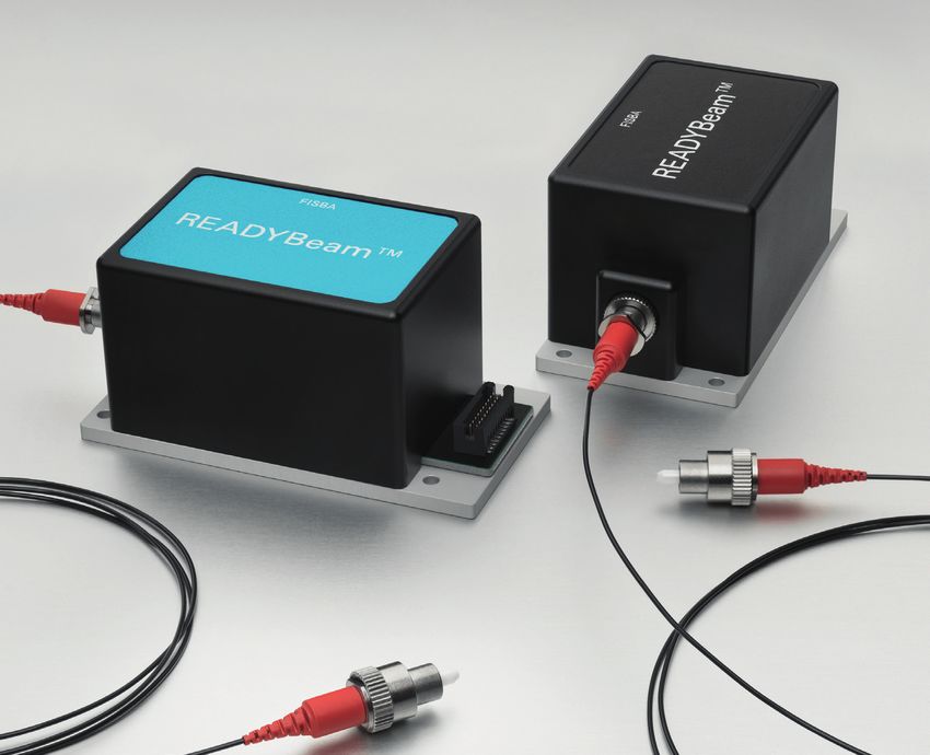
13Technical Specifications
FISBA READYBeam™
Data sheet FISBA READYBeam TM
Technical Specifications
Optical parameters bio ind
Wavelengths 405 nm 488 nm 638 nm 450 nm 520 nm 660 nm
Min. optical power from
≥ 40 mW ≥ 30 mW ≥ 40 mW ≥ 40 mW ≥ 30 mW ≥ 40 mW
fiber
NA fiber 0.12
Laser class 3B
Fiber connector FC/APC
Fiber type Single-mode with or without polarization maintaining properties
Electrical parameters
Power supply 12 V ... 24 V
ON / OFF Enable up to 1 MHz
Modulation
Set power input bandwidth up to 20 kHZ (0..3.3 V -> 10%..100% )
Operation mode cw / modulated
Digital interface RS 485 (ON / OFF Modulation up to 100 Hz)
Mechanical parameters
Dimensions
77 mm x 40 mm x 37 mm
length x width x height
Weight ≤ 200 g
Environmental conditions
Operation temperature 15°C – 40°C
Storage temperature -10°C … +60°C
Thermal properties TEC controlled
Heat dissipation ~ 7 watts
2019 November , all rights reserved
A AG FISBA LLC FISBA Photonics GmbH sales@fisba.com
St.Gallen, Switzerland Tucson, AZ 85712, United States 12489 Berlin, Germany www.fisba.com
1415
FISBA AG                     Rorschacher Str. 268
                             9016 St.Gallen
                             Switzerland

FISBA Photonics GmbH         Schwarzschildstrasse 10
                             12489 Berlin
                             Germany

FISBA LLC                    6296 E. Grant Rd Suite 150
                             Tucson, AZ 85712
                             United States

FISBA (Shanghai) Co., Ltd.   9F-4
                             World Square Building, No. 855
                             Pudong South Rd.
                             Shanghai
                             China

                             fisba.com | readybeam@fisba.com
Vous pouvez aussi lire