LG BNU-LW(Lonworks Gateway) - Installation Manual
←
→
Transcription du contenu de la page
Si votre navigateur ne rend pas la page correctement, lisez s'il vous plaît le contenu de la page ci-dessous
ENGLISH
                                                             LG
LG
BNU-LW(Lonworks Gateway)

                                                                               ITALIANO
Installation Manual

                                                                               ESPAÑOL
                                                                               FRANÇAIS
                                                                               DEUTSCH

              IMPORTANT
                                                                               CHINESE

               • Please read this Installation Manual carefully and
                 thoroughly before installing and operating your room air
                 conditioner.
               • Please retain this Installation Manual for future reference
                 after reading it thoroughly.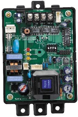
BNU-LW (Lonworks Gateway)

           TABLE OF CONTENTS
Safety Precautions.................................................................................................3
Overall system diagram.........................................................................................7
External wiring diagram ........................................................................................8
    How to set the address for the central controller of the indoor unit
    connected to BNU-LW (Lonworks Gateway).......................................................8
    Communication line specification .......................................................................9
Name of each part................................................................................................10
Installation order ..................................................................................................11
BNU-LW wiring order ...........................................................................................12
Air conditioner/ventilation function table ..........................................................13
    Air conditioner indoor unit function ...................................................................13
    Ventilation indoor unit function ..........................................................................14
BNU-LW remote diagnosis function...................................................................15
    Setting method..................................................................................................15
    Configuration ....................................................................................................16
Setting the indoor unit address ..........................................................................18
    Setting the indoor unit address .........................................................................18
Interfacing with simple central controller..........................................................19
Appendix...............................................................................................................20
    A/C Objects.......................................................................................................20
    Air conditioner control/monitoring point ............................................................21
    Ventilation control/monitoring point...................................................................22
    Network variables .............................................................................................23

2 Lonworks Gateway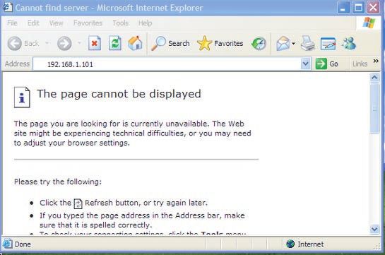
Safety Precautions

       Safety Precautions
To prevent injury to the user or other people and property damage, the following instructions

                                                                                                    ENGLISH
must be followed.
■ Incorrect operation due to ignoring instruction will cause harm or damage. The seriousness is
  classified by the following indications.

      WARNING                 This symbol indicates the possibility of death or serious injury.

      CAUTION                 This symbol indicates the possibility of injury or damage.

■ Meanings of symbols used in this manual are as shown below.

                                               Be sure not to do.

                                   Be sure to follow the instruction.

                                        WARNING
■ Operation

 Do not operate or stop           Ask for Product                    Use standard parts.
 the unit by inserting or         equipment at the service
 pulling out the power            center or establishment
 plug.                            certainly at the specialty
                                  store.
                                                                     • Use of non standard parts
 • It will cause electric shock   • It can cause an accident,
                                                                       can cause electric shock,
   or fire due to heat              electric shock, explosion
                                                                       explosion, injury,
   generation.                      or injury.
                                                                       breakdown.
                                                                                        BNU-LW

                                                          BNU-LW

                                                                            Standard Parts

                                                                         Installation Manual 3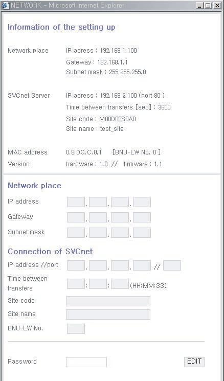
Safety Precautions

 While re-installing the          Do not use the power cord                Do not disjoint randomly or
 established product, notify      near Flammable gas or                    repair and remodel the
 the service center or            combustibles, such as                    product.
 establishment specialty          gasoline, benzene, thinner,
 store.                           etc.
 • It can cause an accident,      • It may cause an explosion              • It may cause fire and
   electric shock, explosion,       or fire                                  electric shock
   injury.shock.
                                                                                                  BNU-LW

                                               BNU-LW

              BNU-LW

                                                          x
                                                        Wa Thinner

 If water enters the product, turn the power               Keep the product away from the places
 switch of the main body of appliance off.                 which can have moisture.
 • After taking the power-plug out from the                • Water may enter the unit and degrade the
   socket, contact the service center.                       insulation. It may cause an electric shock.

                                                                                     BNU-LW

                       BNU-LW

■ During usage

 Do not change or extend the      Do not use concert with in               Unplug the unit if strange
 conductor at random.             the octopus-like legs way.               sounds, smell, or smoke
                                                                           comes from it.
 • It can cause fire and          • It can cause fire and                  • It may cause fire and
   electric shock.                  electric shock                           electric shock accident.

                                                                                         BNU-LW

4 Lonworks Gateway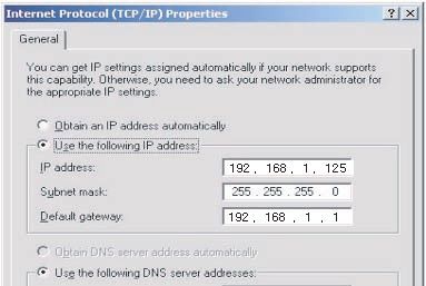
Safety Precautions

Do not put firearms near                 Do not put an electric heater   Do not spill water inside
product.                                 or conductor near to the        product.
                                         product.

                                                                                                                 ENGLISH
• It can cause fire.                     • It can cause fire and         • It can cause electric
                                           electric shock.                 shock and breakdown.

                                                 BNU-LW

                                BNU-LW

                                                                                      BNU-LW

Do not place heavy goods                 Hold the plug by the head of    Do not place heavy goods
on wire.                                 the power plug when taking      on product.
                                         it out.
• It can cause fire and                  • It may cause electric         • It can cause product
  electric shock.                          shock and damage.               breakdown.

       BNU-LW

                                                                                                        BNU-LW

That increase in case of                 Protect the product from        Do not apply shock to
product was been flood                   handling by a children.         product.
certainly in the service
center or establishment
specialty store commit .
• I am responsible for fire              • It can cause accident and     • I am responsible for
  and electric shock.                      product breakdown.              breakdown in case of
                                                                           shock to product.
                                                            BNU-LW

                                                                                               BNU-LW

                       BNU-LW

                                                                             Installation Manual 5
Safety Precautions

                                                CAUTION
■ During usage

 Clean by soft hands using a               Do not place any live part on   Use recommended Adapter.
 cleaning material like a soft             the surface having water.
 cloth.
 • It can result in fire and               • It can cause product          • Otherwise it can result in
   product transformation.                   breakdown.                      product breakdown

                                                                                                  BNU-LW

                                                              BNU-LW

                                  BNU-LW

              x
            Wa Thinner

 Avoid contact to the metallic             Hold the plug by the head of
 goods such as necklace,                   the power plug when taking
 coin, key, a watch which                  it out.
 may touch the battery even
 for a short-time.
 • It may cause product                    • It may cause electric
   breakdown and injury.                     shock and damage.

                         BNU-LW

6 Lonworks Gateway
Overall system diagram

  Overall system diagram

                                                                                                              ENGLISH
                                                                                     Simple central
                                                                                       controller

                                                                                  485 communication

                                 * Can be connected to 64 indoor units (Ventilation+Air conditioner)

                   Ventilation      A/C

* PNF-B16A1 (Lon Gateway) can be used in connection with the simple central
  controller.

                                                                                     Installation Manual 7
External wiring diagram

        External wiring diagram
   How to set the address for the central controller of
   the indoor unit connected to BNU-LW (Lonworks Gateway)

          LON protocol
          BMS system

                 Air conditioner

          RS485

                 RI485               Central controller address(0.0)   (0.1) . . . . . . . . . . . . (0.F)
BNU-LW

                 RI485               Central controller address(1.0)   (1.1) . . . . . . . . . . . . (1.F)

               Central controller               (2.1)                  (2.2)                          (2.3)
               address(2.0)

               Central controller               (2.5)                  (2.6)                          (2.7)
               address(2.4)

• When the address of the indoor unit of the air conditioner is duplicated with that of the ventilation
  unit, it will not operate normally.
• Maximum of 64 units of the indoor unit (Air conditioner+Ventilation) can be connected to the BNU-
  LW.
• It is recommended to connect 16 units of PI485 and maximum of d32 PI485 units to the BNU-LW.
• Ventilation products cannot be interfaced with the simple central controller.

8 Lonworks Gateway
External wiring diagram
Communication line specification
1. RS-485 communication line specification: 0.75mm2 or above 2C shield, product to product: 200M,
ENGLISH
total length: 1km
2. FT-10 communication line: Refer to the following table.
Cable Type Line thickness (AWG) Diameter
TIA 568A Category 5 cable 24 0.5mm
Belden 88471 (PVC jacket) or 16 1.3mm
equivalent cable
Belden 85102(Tefzel jacket) or 16 1.3mm
equal cable
Level IV cable 22 0.65mm
JY(st)Y 2x2x0.8 20.4 0.8mm
* Nod to node distance (max): 250m, maximum distance: 450m
* AWG: American Wire Gauge
Installation Manual 9Name of each part
Name of each part
LONWORKS GATEWAY
1
2
3
4
5
6
7
8
1 BUS_A: 485 communication line A (+)
2 BUS_B: 485 communication line B (-)
3 F1, F2: Fire detection function (external device) contact point connection
4 LAN: LAN port necessary for web function
5 LON: TP/FT-10 communication line (Lonworks system communication line) non-polarity
6 PWR: Connection to DC 12V power adapter
7 12V: Connection when not using DC 12V power adapter
8 GND: Connection when not using GNS adapter
ALIVE/WINK: It flashes every 1 second when it is normal
It flashes 5 times when receiving WINK command from Lonworks system
(Green)
SERVICE: It is turned off when it is normal and flashes when it is not connected to the
Lonworks system. It is turned on when the service switch is pressed.
SERVICE SWITCH: When you press the switch the Neuron ID is transmitted to the
Lonworks system, and the service LED is turned on.
BNU-LW (PNF-B16A1) product is a product certified of LON-MARK, an international
standard. (Lon Mark Version 3.3)
No. 6 and No. 7,8 are all for power supply. Therefore, only one of two combinations should be used.
When DC 12V is used for the power, Connect No. 6 to the power (not necessary to use No. 7,8.)
When DC 12V is NOT used for the power, Connect No. 7, 8 to the power (not necessary to use No. 6.)
10 Lonworks GatewayInstallation order
Installation order
1. Install the product according to the setting of the central controller address of the indoor unit and the
ENGLISH
DIP S/W of PI485. (Set the DIP switch No. 4 to ON.)
(Refer to the PI485 installation manual for details.)
2. Connect BUS_A and BUS_B (485 communication line) while paying attention to the connecting
polarity. (Refer to the next page.)
3. LON (TP/FT-10 line‡Lonworks Gateway communication line connection) TP/FT-10 communication
line does not have polarity. Connect the 2 communication lines to BMS.
4. PWR (Power supply)
You can select either one of the two for the power supply.
Use DC 12V power adapter
Connect to No. 6 in name of each part.
When separate DC12 can be supplied
Connect 12V and GND to No. 7 and 8 terminals.
5. When you press the service switch after connecting to the Lonworks system, the service LED is
turned on and the neuron ID is automatically transmitted to the Lonworks system.
6. Check whether the service LED is in normal condition (OFF condition) within 10 minutes. If the
service LED is in normal condition, the installation has been done normally.
7. When using the fire detection port, connect the two terminals of the fire diction sensor to F1 and F2.
(Fire detection sensor must be used for DC output of 12V or below.)
8. After the installation, connect the LAN cable between the PCs to use the web server so that you
can check whether the LG product has been installed normally. – Refer to the remote diagnosis
function part (page 16) for details.
When connecting the signal line to the terminal of Lonworks Gateway, always use a
manual driver.
(Careful attention is required not to damage the terminal block and PCB.)
Installation Manual 11BNU-LW wiring order
BNU-LW wiring order
LG does NOT supply this section ( Connection and Installation)
LonWorks
Adaptor
BMS Control (PC)
TP/FT-10
A
B
+10V
GND
PI485
terminal Central
controller PI485
F1 F2 LAN LON PWR 12V GND VOC 10V
GND GND
C BUS_A
D BUS_B
LG supply
Power
Fire detection sensor
(Use DC 12V or below)
[Wiring sequence]
1. Connect 485 communication line 4. Interface with simple central controller
- Pay attention to BUS A and BUS B polarity - Set the DIP S/W No. 2 of the simple central
(Refer to the G/W manual for DIP S/W controller to ON and configure the setting
information for 485 G/W.) according to the rotary S/W address. (Refer
2. Connect the Lonworks communication line to setting part when connection to simple
(TP/FT-10) central controller (page 20) for details.)
- No polarity. 5. Connect fire detection sensor
3. Power supply (Select one from No. 1 or 2) - When the signal of DC 12 or below is
Use DC 12V adapter transmitted in case of a fire, the indoor unit
- Connect to No. 6 jack from name of each and ventilation product that is connected to
part. BNU-LW will all be turned off.
Supply DC 12V to installation site
- Connect 12V and GND to No. 7 and 8
terminals.
12 Lonworks GatewayAir conditioner/ventilation function table
Air conditioner/ventilation function table
Air conditioner indoor unit function
ENGLISH
Classification Control Monitoring
Air conditioner
BMS
Function
BNU-LW
BNU-LW
Air conditioner
BMS
Indoor unit individual control O O
Operating mode change O O
Fan level change O O
Temperature adjustment function O O
Lock function O O
Automatic fan direction O O
Indoor unit temperature check X O
Error check X O
Simultaneous operation/stop O X
Binding (connection) function: Binding function refers to the case when the output of a unit has been
bound to the input of another unit and the process of input change from
the output change. The binding function is possible with Lon unit of
other manufacturer.
Ex) When the ON/OFF output of the indoor unit No. 1 is bound to ON/OFF input of indoor unit of No. 2
and when the indoor unit No. 1 is turned on, the indoor unit No. 2 also gets turned on from
receiving the signal.
Installation Manual 13Air conditioner/ventilation function table
Ventilation indoor unit function
Classification Control Monitoring
Ventilation
BMS
Function
BNU-LW
BNU-LW
Ventilation
BMS
Indoor unit individual control O O
Operating mode change O O
Fan level change O O
User operation mode
O O
(Quick ventilation, power save, heating)
Lock function O O
Error check X O
Simultaneous operation/stop O X
Binding (connection) function: Binding function refers to the case when the output of a unit has been
bound to the input of another unit and the process of input change from
the output change. The binding function is possible with Lon unit of
other manufacturer.
Ex) When the ON/OFF output of the indoor unit No. 1 is bound to ON/OFF input of indoor unit of No. 2
and when the indoor unit No. 1 is turned on, the indoor unit No. 2 also gets turned on from
receiving the signal.
14 Lonworks GatewayBNU-LW remote diagnosis function
BNU-LW remote diagnosis function
Setting method
ENGLISH
1. Connect the LAN line between the PC
and the LAN port of the BNU-LW.
LAN(cross cable)
2. Set the network IP of the used PC to
192.168.1.xxx (except 101).
3. Enter 192.168.1.101 in the Internet
Explorer.
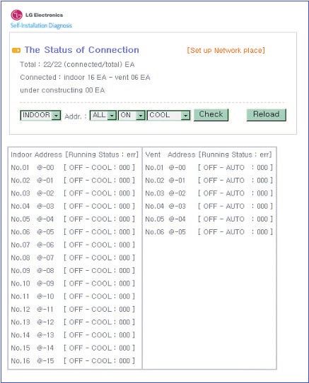
4. The above picture is shown when
connected normally.
• Initial ID: lonwork
• Initial password: lonwork
• Enter the total number of connected
indoor units in the Total Unit block.
Installation Manual 15BNU-LW remote diagnosis function
Configuration
• After entering the ID and password,
"A" the air condition and ventilation
products currently connected are
displays as shown in the picture.
• “A” part displays the number of air
condition and ventilation products
are currently connected.
"B"
• When you would like to control a
product ➀ Select the product – ➁
Set the address – ➂ Command
ON/OFF – ➃ Select the mode – ➄
Click on check to control the
product.
• When you would like to check the
current status ➅ Click on Reload
and you will be able to check the
current indoor unit status in the “B”
part.
• When you would like to change the
IP, click on [Set up Network place]
to change the IP.
16 Lonworks GatewayBNU-LW remote diagnosis function
A A: It displays the current IP, Gateway,
Subnet mask information.
ENGLISH
When you would like to use the
SVCnet Server, it displays the
SVCnet Server information.
It displays the MAC address
information.
It displays the current version
information of the BNU-LW.
B: When you would like to change the IP
B and Gateway, Subnet mask
information, press the Edit button next
to the information you would like to
change.
C: This is the space to enter the SVCnet
C Server information to connect.
SVCnet Server is the service that
monitors the air conditioner status
connected to BNU-LW through the
LAN in the future by the LG
Electronics Service Center to provide
early notification in case of a problem.
D: In order to prevent the network or
D arbitrary change, a security function
has been applied for you to enter the
initial login password to change the
network setting.
Installation Manual 17Setting the indoor unit address
Setting the indoor unit address
Setting the indoor unit address
When using the wired remote controller
1. Press the week day and reservation set/cancel buttons
AUTO SWING OPERATION SET TEMP
Room Temp
FAN SPEED SUB FUNCTION simultaneously for 3 seconds.
HI AUTO Heater Preheat
MED Defrost Humidify
LO
JET
Filter Out door 2. By using the temperature adjustment button, set the indoor unit
Time ZONE 1 2 3 4
Timer
On Off
Operation unit Program set address.
Set no. Time 01 03 05 07 09 11 13 15 17 19 21 23
Setting range: 00~FF
3. When you press the week day and reservation set/cancel
buttons simultaneously for 3 seconds, the address setting is
Timer Cancel
completed.
Temperature adjustment
Program Week Holiday
Plasma
Set/Clr
Hour Min RESET Group No. Indoor unit No.
Temperature
When using the wireless remote controller
Address setting mode
1. ➀ Press the top left button for more than 3 seconds. ➁ While the top left
button pressed, press the Reset button .
The wireless remote controllers have different shapes according to
the model.
2. By using the temperature adjustment button, set the indoor unit address.
Setting range: 00~FF
3. After setting the address, press the ON/OFF button toward the indoor
unit 1 time.
4. The indoor unit will display the set address to complete the address
setting. (The address display time and method can differ by the indoor
unit type.)
ON OFF
5. Reset the remote controller to use the general Temperature
adjustment
operation mode.
SET CANCEL
Address check mode Group No.
PLASMA
1. With the top right button pressed, press the Reset Indoor unit No.
button.(Press the left button for more than 3
seconds.)
2. Press the ON/OFF button toward the indoor unit 1 time, and the indoor
unit will display the set address in the display window. (The address
display time and method can differ by the indoor unit type.)
3. Reset the remote controller to use the general operation mode.
❈ The above function might not work for some remote controllers depending on the manufactured
date of the wired/wireless remote controller.
It is not relevant for the consumer use and you can set the address with a remote controller that has
the address setting functionality during the installation.
18 Lonworks GatewayInterfacing with simple central controller
Interfacing with simple central controller
ENGLISH
How to interface with simple central
controller
• When interfacing with simple central controller, turn the DIP
S/W No. 2 of the simple central controller ON.
• Set the rotary S/W to the group address of the indoor unit you
would like to control.
How to set PI-485
How to set PI-485
• BNU-LW uses LGAP communication protocol.
You can set the DIP S/W No. 1 and No. 4 of PI-485 ON.
Installation Manual 19Appendix
Appendix
• The appendix carries information necessary for interfacing with BMS and not necessary for actual
installation.
A/C Objects
Standard Fundtion Block
SNVT_switch nviOnOff SCC(8500)FB SNVT_switch nvoOnOff
SNVT_hvac_mode nviHeatCool SNVT_hvac_mode nvoHeatCool
SNVT_switch nviFanSpeedcmd SNVT_switch nvoFanSpeed
Indoor/
SNVT_switch nviLock SNVT_switch nvoLock
Ventilator unit
SNVT_switch nviSwing SNVT_switch nvoSwing
Network Varlables
SNVT_switch nviSetPoint SNVT_temp_P nvoSetPoint
SNVT_switch nviUser SNVT_hvac_status nvoUnitStatus
SNVT_switch nviSpaceTemp SNVT_count nvoUser
SWITCH(3200)FB
SNVT_switch
nviTotalOnOff_Indoor
Total SNVT_switch nvoSwitch
SNVT_switch Control
nviTotalOnOff_Vent
Control Monitoring
On/Off command On/Off status monitoring
Mode selection command Mode status monitoring
Fan level selection command Fan level status monitoring
Indoor unit lock command Lock status monitoring
Fan direction command Fan direction status monitoring
Temperature setting command Temperature setting status
monitoring
Ventilation additional function command Current temperature monitoring
(Only applies for ventilation product)
Air conditioner total On/Off control Error display
Ventilation total On/Off control Ventilation additional function
status monitoring (Only applies
for ventilation product)
• You can enable control and monitoring as shown in the figure for one air conditioner/ventilation unit.
• The network variable can differ from the actual.
(Refer to the XIF file for correct network variable.)
20 Lonworks GatewayPoint Object Name Object Unit
Name (nn: Air conditioner and ventilation
No. group/indoor unit address) Type code 0 code 1 code 2 code 3 code 4 code 5 code 9 code14
1 ON/OFF (setting) SNVT_switch nviOnOff_nn input Stop Operation
2 ON/OFF (status) SNVT_switch nvoOnOff_nn output Stop Operation
3 Lock (setting) SNVT_switch nviLock_nn input Cancel Setting
4 Lock (status) SNVT_switch nvoLock_nn output Cancel Setting
5 Operation Mode (setting) SNVT_hvac_modenviHeatCool_nn input Auto Heating Cooling Fan Dry
6 Operation Mode (status) SNVT_hvac_mode nviHeatCool_nn output Auto Heating Cooling Fan Dry
7 Swing(setting) SNVT_switch nviSwing_nn input Cancel Setting
8 Swing(status) SNVT_switch nvoSwing_nn output Cancel Setting
9 Fan speed(setting) SNVT_switch nviFanSpeedCmd_nn input Low Med High Auto Super Low
10 Fan speed(status) SNVT_switch nvoFanSpeed_nn output Low Med High Auto Super Low
Air conditioner control/monitoring point
11 Set Room Temperature SNVT_temp_p nviSetPointCmd_nn input °C
12 Set Room Temperature SNVT_temp_p nvoSetPoint_nn output °C
13 Room Temperature SNVT_temp_p nvoSpaceTemp_nn output °C
14 Error Code SNVT_hvac_status nvoUnitStatus_nn output no errorRefer to the LG Air Conditioner Error Code.
Installation Manual 21
Appendix
ENGLISHPoint Object Name Object Unit
Name (nn: Air conditioner and ventilation
No. group/indoor unit address) Type code 0 code 1 code 2 code 3 code 5 code 9
Appendix
1 ON/OFF (setting) SNVT_switch nviOnOff_nn input Stop Operation
2 ON/OFF (status) SNVT_switch nvoOnOff_nn output Stop Operation
22 Lonworks Gateway
3 Lock (setting) SNVT_switch nviLock_nn input Cancel Setting
4 Lock (status) SNVT_switch nvoLock_nn output Cancel Setting
5 Operation Mode (setting) SNVT_hvac_modenviHeatCool_nn input Auto Heat exchange Normal
6 Operation Mode (status) SNVT_hvac_mode nviHeatCool_nn output Auto Heat exchange Normal
7 Fan speed(setting) SNVT_switch nviFanSpeedCmd_nn input Low High Very high
Ventilation control/monitoring point
8 Fan speed(status) SNVT_switch nvoFanSpeed_nn output Low High Very high
9 Error Code SNVT_hvac_status nvoUnitStatus_nn output Refer to the LG Air Conditioner Error Code.
10 User Mode(setting) SNVT_count nviUser_nn output Quick Power save heat
11 User Mode(status) SNVT_count nvoUser_nn output Quick Power save heatAppendix
Network variables
1) Individual operation/stop input/output (Air conditioner/ventilation)
ENGLISH
Function Operation/stop input
Input Using NV Network input variable : SNVT_switch nviOnOff_n
Operation It controls the operation/stop of each product (air conditioner/ventilation)
Function Operation/stop status display
Output Using NV Network output variable : SNVT_switch nvoOnOff_n
Operation It monitors the operating status of each product (air conditioner/ventilation)
Valid Range
NV Filed Operation
value not used (set in 0% usually)
0 = Air conditioner/ventilation product OFF
SNVT_switch
( Index : 95 ) state 1 = Air conditioner/ventilation product ON
Default Value
2) Operating mode input/output (Air conditioner/ventilation)
Function Operating mode command input
Input Using NV Network input variable : SNVT_hvac_mode nviHeatCool_n
Operation It controls the operating mode of each air conditioner/ventilation product.
Function Operating mode status display
Output Using NV etwork output variable : SNVT_hvac_mode nvoHeatCool_n
Operation It monitors the operating status of each air conditioner/ventilation product.
Valid Range
NV Operation
HVAC_AUTO : 0 = AUTO mode(air conditional), Auto (ventilation)
HVAC_HEAT : 1 = Heat mode(air conditional), heat exchange(ventilation)
SNVT_hvac_mode HVAC_COOL: 3 = Cool mode (cool)
( Index : 108 ) HVAC_FAN_ONLY: 9 = Fan mode (fan) normal ventilation
HVAC_DEHUMID:14=Dry Mode (dehumidication)
Default Value
Installation Manual 23Appendix
3) Fan level command input/output (Air conditioner/ventilation)
Function Fan level command input
Input Using NV Network input variable : SNVT_switc nviFanSpeedCmd_n
Operation It controls the fan level of each indoor unit.
Function Fan level status display
Output Using NV Network output variable : SNVT_switch nvoFanSpeed_n
Operation It monitors the fan level of each product (air conditioner/ventilation)
Valid Range
NV Filed Operation
1: Air conditioner, ventilation low fan
2: Air condition med fan, ventilation high fan
value 3: Air condition high fan, ventilation very high fan
SNVT_switch
( Index : 95 ) 4: Air condition, ventilation auto fan
5. Air conditioner super low fan
state 0: Product not applied, 1: Product applied
Default Value
4) Lock input/output (Air conditioner/ventilation)
Function Lock setting command input
Input Using NV Network input variable : SNVT_switch nviLock_n
Operation It controls the lock status of each product (air conditioner/ventilation)
Function Lock status display
Output Using NV Network output variable : SNVT_switch nvoLock_n
Operation It monitors the lock status of each product (air conditioner/ventilation)
Valid Range
NV Filed Operation
value not used (set in 0% usually)
0 = Air conditioner/ventilation product lock OFF
SNVT_switch
state 1 = Air conditioner/ventilation product lock ON
( Index : 95 )
Default Value
24 Lonworks GatewayAppendix
5) Fan direction auto input/output (Only applies to air conditioner)
Function Fan direction auto command input
Input Using NV Network input variable : SNVT_switch nviSwing_n
ENGLISH
Operation It controls the fan direction of each product (air conditioner/ventilation)
Function Fan direction auto status display
Output Using NV Network output variable : SNVT_switch nvoSwing_n
Operation It monitors the fan direction of each product (air conditioner/ventilation)
Valid Range
NV Filed Operation
value not used (set in 0% usually)
0 = Fan direction fixed for air conditioner product
SNVT_switch
state 1 = Fan direction auto for air conditioner product
( Index : 95 )
Default Value
6) Temperature setting input/output (Only applies to air conditioner)
Function Set temperature range input
Input Using NV Network input variable : SNVT_switch nviSetPoint_n
Operation It controls the temperature setting of each product (air conditioner/ventilation)
Function Set temperature range status display
Output Using NV Network output variable : SNVT_switch nvoSetPoint_n
Operation It monitors the set temperature of each product (air conditioner/ventilation)
Valid Range
NV Operation
At Cool mode : 18 ~ 30°C
SNVT_switch At Heat mode : 18 ~ 30°C
( Index : 95 ) At Dry mode and Fan mode : Not available
Default Value
Installation Manual 25Appendix
7) Indoor temperature status display (Only applies to air conditioner)
Function Indoor temperature status display
Output Using NV Network output variable : SNVT_switch nvoSpaceTemp_n
Operation It monitors the indoor temperature.
Valid Range
NV Operation
At Cool mode : 10 ~ 40°C
SNVT_switch At Heat mode : 10 ~ 40°C
( Index : 95 ) At Dry, Fan mode : Not available
Default Value
8) Error output (Air conditioner/ventilation)
Function Error status display
Output Using NV Network input variable : SNVT_hvac_Status nvoUnitStatus_n
Operation It monitors the error status of each product (air conditioner/ventilation)
Valid Range
NV Filed Operation
Mode Currently operating mode display
Heat_output_primary Not used
Heat_output_Secondary Not used
SNVT_switch Cool_output Not used
( Index : 112 ) Cool_output Not used
Econ_output Not used
fan_output Not used
In_alarm Error code display
* Refer to the Error Code table of the product manual for the error code.
26 Lonworks GatewayAppendix
9) Ventilation function command (Only applies to ventilation product)
Function Ventilation user operating mode input
Input Using NV Network input variable : SNVT_count nviUser_n
ENGLISH
Operation It controls the product function of each ventilation product.
Function Ventilation user operating mode status
Output Using NV Network output variable : SNVT_count nvoUser_n
Operation It monitors the function status of each ventilation product.
Valid Range
NV Filed Operation
0 = Not used
SNVT_count 1 = Quick mode
value
( Index : 8 ) 2 = Power save mode
3 = Heat
10) Total operation/stop air conditioner indoor unit
Function Total stop command input
Input Using NV Network input variable : SNVT_switch nviTotalONOFF_indoor
Operation It turns ON or OFF all the indoor units.
11) Total operation/stop ventilation indoor unit
Function Total stop command input
Input Using NV Network input variable : SNVT_switch nviTotalONOFF_indoor
Operation It turns ON or OFF all the ventilation units.
Valid Range
NV Filed Operation
value not used
SNVT_switch 1 = All ON indoor/Vent unit
state
( Index : 95 ) 0 = All OFF indoor/Vent unit
Default Value
Installation Manual 27Memo 28 Lonworks Gateway
LG
LG
BNU-LW(Lonworks Gateway)
Manuel d’installation

                                                                       FRANÇAIS

               IMPORTANT
               • Veuillez lire en entier ce manuel d'installation le
                 produit.
               • Après avoir lu en entier ce manuel d'installation,
                 veuillez le conserver pour future consultation.
BNU-LW (Lonworks Gateway)
TABLE DES MATIÈRES
Mesures de sécurité...............................................................................................3
Diagramme du système général ...........................................................................7
Diagramme de l’installation électrique externe...................................................8
Comment mettre l’adresse pour la télécommande centrale de
l’appareil en salle connecté au BNU-LW (Lonworks Gateway)...........................8
Spécification de la ligne de communication .......................................................9
Nom de chaque partie .........................................................................................10
Schéma d’installation ..........................................................................................11
Schéma de l’installation électrique BNU-LW.....................................................12
Tableau des fonctions de l’air conditionné/ventilation ....................................13
Fonctions d’air conditionné de l’appareil en salle .............................................13
Fonction d’air conditionné de l’appareil en salle ...............................................14
Fonctions de diagnose à distance BNU-LW ......................................................15
Méthode de fixation ........................................................................................15
Configuration ....................................................................................................16
Fixation de l’adresse de l’appareil en salle .......................................................18
Fixation de l’adresse de l’appareil en salle .......................................................18
Interface avec la télécommande centrale simple..............................................19
Annexe ..................................................................................................................20
Objets A/C ........................................................................................................20
Point de contrôle/monitorage de l’air conditionné .............................................21
Point de contrôle/monitorage de ventilation ......................................................22
Variables de réseau ..........................................................................................23
2 Lonworks GatewayMesures de sécurité
Mesures de sécurité
Pour éviter que l’usager ou une autre personne se blesse ou que l’appareil subisse des
dommages matériels, respecter les indications ci-dessous.
■ Un usage incorrect dû au non-respect de ces instructions pourrait causer des dégâts ou
endommager l’appareil. Leur degré de gravité est classée de la manière suivante.
AVERTISSEMENT Ce symbole indique un danger de mort ou de dommages graves.
PRÉCAUTION Ce symbole indique un risque seulement pour l’appareil.
■ Voir ci-dessous la signification des symboles utilisés dans le manuel.
A ne pas faire.
Suivre les instructions
AVERTISSEMENT
■ Fonctionnement
FRANÇAIS
Ne pas brancher ni Demander au service Utilisez les pièces
débrancher l’appareil central ou à un magasin standard.
pour le mettre en marche spécialisé l’outillage
ou l’arrêter. nécessaire à l’installation
de l’appareil.
• L’usage de piéces non
• Risque de décharge • Risque d’accident, de
standard peut provoquer
électrique ou d’incendie décharge électrique,
décharge électrique,
par suite de surchauffe. d’explosion ou de
explosion, dommage ou
dommage.
panne.
BNU-LW
BNU-LW
Pièces standard
Manuel d’Installation 3Mesures de sécurité
Pendant la réinstallation de Ne pas utiliser le câble Ne pas démonter au hasard
l’appareile, informer le d’alimentation près de gaz l’appareil, ni le réparer ni le
service central ou le inflammables ou de remodeler.
magasin spécialisé. combustibles tels que : essence,
benzène ou diluant, etc.
• Risque d’accident, de • Risque d’explosion ou • Risque de décharge
décharge électrique, d’incendie. électrique ou d’incendie.
d’explosion, de dommage.
BNU-LW
BNU-LW
BNU-LW
x
Wa Thinner
Au cas où de l’eau entrerait dans l’appareil, éteindre Maintenir l’appareil hors des lieux humides.
l’interrupteur du corps principal de l’appareil.
• Après l’avoir débranché, contacter le • De l’eau pourrait entrer dans l’appareil et
service central. détériorer l’isolation. Risque de décharge
électrique.
BNU-LW
BNU-LW
■ Pendant l’utilisation.
Ne pas changer le Ne pas utiliser avec une Débrancher l’appareil s’il
conducteur ni l’allonger. prise multiple. émet des bruits, une odeur
ou de la fumée.
• Risque d’incendie et de • Risque d’incendie et de • Risque d’incendie et de
décharge électrique. décharge électrique. décharge électrique.
BNU-LW
4 Lonworks GatewayMesures de sécurité
Ne pas placer d’ objets Ne pas placer de radiateur Ne pas renverser d’eau dans
incandescents (ayant une électrique ou de conducteur l’appareil.
flamme) près de l’appareil. près de l’appareil.
• Risque d’incendie. • Risque d’incendie et de • Risque de décharge
décharge électrique. électrique et de panne.
BNU-LW
BNU-LW
BNU-LW
Ne pas placer d’objets Tenir le câble par la prise Ne pas placer d’objets
pesants sur le câble. lors du débranchement. pesants sur l’appareil.
• Risque d’incendie et de • Risque de décharge • Risque de panne de
décharge électrique. électrique et de dommage. l’appareil.
BNU-LW
BNU-LW
FRANÇAIS
En cas d’inondation de Eviter que l’appareil soit Ne pas faire subir de choc à
l’appareil votre manipulé par des enfants. l’appareil.
responsabilité serait engagée
face au service centrale ou
au magasin spécialisé.
• Je suis responsable en • Risque d’accident et de • Je suis responsable en
cas d’incendie et de panne de l’appareil. cas de panne pour raison
décharge électrique. de choc.
BNU-LW
BNU-LW
BNU-LW
Manuel d’Installation 5Mesures de sécurité
PRÉCAUTION
■ Pendant l’usage.
Nettoyer délicatement Ne placer aucune partie vitale Utiliser l’adaptateur
l’appareil avec une matière sur une surface mouillée. recommandé.
telle qu’un chiffon doux.
• Risque d’incendie ou de • Risque de panne. • Risque de panne.
modification de l’aspect
de l’appareil.
BNU-LW
BNU-LW
BNU-LW
x
Wa Thinner
Eviter le contact avec des objets Tenir le câble par la prise
métalliques tels que chaîne, lors du débranchement.
monnaie, clé, une montre qui
serait en contact avec la batterie
même pour peu de temps.
• Risque de panne ou de • Risque de décharge
dommage. électrique ou de
dommage.
BNU-LW
6 Lonworks GatewayDiagramme du système général
Diagramme du système général
Fourni par LG
Télécommande
centrale simple
485 communication
* Peut être connecté à 64 appareils en salle (Ventilation + Air conditionné)
FRANÇAIS
Ventilation A/C
* Le PNF-B16A1 (Lon Gateway) peut être utilisé en connexion avec la télécommande
centrale simple.
Manuel d’Installation 7Diagramme de l’installation électrique externe
Diagramme de l’installation électrique externe
Comment mettre l’adresse pour la télécommande centrale de
l’appareil en salle connecté au BNU-LW (Lonworks Gateway)
Protocole LON
Système BMS
< Nombre maximal d’appareils en salle connectés : 64 unités>
Air conditionné
RS485
RI485 Adresse de la télécommande centrale(0.0)(0.1) . . . . . . . . . . . . (0.F)
BNU-LW
RI485 Adresse de la télécommande centrale(1.0) (1.1) . . . . . . . . . . . . (1.F)
Adresse de la (2.1) (2.2) (2.3)
télécommande
centrale(2.0)
Adresse de la (2.5) (2.6) (2.7)
télécommande
centrale(2.4)
• Lorsque l’adresse de l’appareil en salle de l’air conditionné est doublée avec celle de l’unité de
ventilation, ceci ne marchera pas correctement.
• Un maximum de 64 appareils en salle (Air conditionné + Ventilation) peut être connecté au BNU-LW.
• Il est recommandé de connecter 16 appareils à PI485 et un maximum de 32 appareils PI485 au
BNU-LW.
• Les produits de ventilation ne peuvent pas être opérés avec la télécommande centrale simple.
8 Lonworks GatewayDiagramme de l’installation électrique externe
Spécification de la ligne de communication
1. Spécification de la ligne de communication RS-485 : 0.75mm2 ou plus de 2C shield, produit par
produit : 200M, longueur : 1km.
2. Ligne de communication FT-10 : consultez le tableau suivant
Type de câble Epaisseur de ligne (AWG) Diamètre
TIA 568A Category 5 cable 24 0.5mm
Belden 88471 (PVC jacket) or 16 1.3mm
equivalent cable
Belden 85102(Tefzel jacket) or 16 1.3mm
equal cable
Level IV cable 22 0.65mm
JY(st)Y 2x2x0.8 20.4 0.8mm
* Distance de la tête au noeud (max) : 250m, distance maximale : 450m
* AWG : American Wire Gauge (Calibre métallique)
FRANÇAIS
Manuel d’Installation 9Nom de chaque partie
Nom de chaque partie
Lonworks gateway
1
2
3
4
5
6
7
8
1 BUS_A : 485 ligne de communication A (+)
2 BUS_B : 485 ligne de communication B (-)
3 F1, F2 : Fonction de détection de feu (appareil externe) connexion du point de contact
4 LAN : port LAN nécessaire pour la fonction réseau
5 LON : ligne de communication TP/FT-10 (ligne de communication du système Lonworks) non polarité
6 PWR : connexion à un convertisseur de puissance DC 12V.
7 12V : Connexion lors de la non utilisation du convertisseur de puissance DC 12V
8 GND: Connexion lors de la non utilisation du convertisseur GNS
ALIVE/WINK : il scintille toutes les secondes lorsqu’il est normal
Il scintille 5 fois lorsqu’il reçoit une commande WINK du système Lonworks (Vert)
SERVICE :il est éteint quand il est normal et il scintille lorsqu’il n’est pas connecté au
système Lonworks.
Il est allumé quand le commutateur de service est pressé.
COMMUTATEUR DE SERVICE : quand vous pressez le commutateur, l’ID (identité) de
la Neurone est transmise au système Lonworks, et le service LED est mis en marche.
Le produit BNU-LW (PNF-B16A1) est un produit certifié de LonMark, une norme
internationale.(LonMark Version 3.3)
AVERTISSEMENT
Les numéros 6, 7 et 8 sont pour l’alimentation. Cependant, il faut utiliser seulement une des
deux combinaisons.
Si vous utilisez du DC 12V pour l’alimentation, branchez No. 6 à l’alimentation (pas besoin
d’utiliser No. 7 et 8).
Si vous N’UTILISEZ PAS de DC 12V pour l’alimentation, branchez les No. 7 et 8 à
l’alimentation (pas besoin d’utiliser No. 6).
10 Lonworks GatewaySchéma d’installation
Schéma d’installation
1. Installez le produit selon le mode de la télécommande centrale de l’appareil en salle et le DIP S/W
de PI485. (Mettez en marche (ON) le commutateur DIP No. 4)
(Consultez le manuel d’installation du PI485 pour plus de détails).
2. Connectez le BUS_A et le BUS_B (ligne de communication 485)
(Consultez la page suivante).
3. LON (TP/FT – ligne 10‡Lonworks Gateway connexion de la ligne de communication) ligne de
communication TP/FT-10 n’a pas de polarité.
Connectez les deux lignes de communication à BMS.
4. PWR (puissance supérieure)
Vous pouvez sélectionner juste une des deux pour une puissance supérieure.
Utilisez un convertisseur de puissance DC 12V
Connectez à No. 6 dans le nom de chaque partie.
Quand le DC12 séparé peut être fourni
Connectez le 12V et le GND aux terminaux No. 7 et 8.
5. Quand vous pressez le commutateur de service après la connexion au système Lonworks, le
service LED est mis en marche et l’ID du neurone est automatiquement transmis au système
Lonworks.
6. Vérifiez que le service LED est en conditions normales (OFF) au bout de 10 minutes. Si le service
LED est en conditions normales, alors l’installation a été bien faite.
7. Lors de l’utilisation du port de détection de feu, connectez les deux terminaux du senseur de feu à
F1 et F2. (Le senseur de détection de feu doit être utilisé par un DC producteur de 12V ou moins).
8. Après installation, connectez le câble LAN entre les ordinateurs pour utiliser le serveur Web et ainsi
FRANÇAIS
vérifier que le produit LG a été installé normalement. – Consultez la partie des fonctions de
diagnose à distance (page 16) pour plus de détails.
PRÉCAUTION
Quand vous connectez la ligne de signal au terminal du Lonworks Gateway, utilisez
toujours un conducteur manuel.
(Il faut faire très attention à ne pas endommager le bloc terminal et le PCB).
Manuel d’Installation 11Schéma de l’installation électrique BNU-LW
Schéma de l’installation électrique BNU-LW
LG ne fournit pas cette section (connexion et installation)
Adaptateur
Lon Works
Contrôle NMS (PC)
TP/FT-10
A
B
+10V
GND
Terminal
PI485 Télécommande
centrale PI485
F1 F2 LAN LON PWR 12V GND VOC 10V
GND GND
C BUS_A
D BUS_B
Fourni par LG
Puissance
Senseur de détection de feu
(Utilisez le DC 12V ou moins)
[Schéma de l’installation
électrique] 4. Interface avec la télécommande centrale
1. Connectez la ligne de communication 485 simple.
- Faites attention aux polarités du BUS A et - Mettez en marche (ON) le DIP S/W No. 2 de
du BUS B(Consultez le manuel G/W pour la télécommande centrale simple et
l’information DIP S/W pour 485 G/W). configurez le marque selon la direction
2. Connectez la ligne de communication rotative S/W).
Lonworks (TP/FT-10) (Consultez la partie de marque pour la
- Pas de polarité. connexion à la télécommande centrale
3. Puissance supérieure (Sélectionnez l’un des simple (page 20) pour plus de détails).
No. 1 ou 2) 5. Connectez le senseur de détection de feu
Utilisez un convertisseur DC 12V - Quand le signal de DC 12V ou moins est
- Connectez à No. 6 crics du nom de transmis sur la case de feu, l’appareil en
chaque partie. salle et le produit de ventilation connectés au
DC 12V supérieur pour l’installation du site. BNU-LW seront tous arrêtés.
- Connectez le 12V et le GND aux
terminaux No. 7 et 8.
12 Lonworks GatewayTableau des fonctions de l’air conditionné/ventilation
Tableau des fonctions de l’air conditionné/ventilation
Fonctions d’air conditionné de l’appareil en salle
Classification Contrôle Monitorage
Air conditioner
BMS
Fonction
BNU-LW
BNU-LW
Air conditioner
BMS
Télécommande individuelle de l’appareil en salle O O
Changement du mode de fonctionnement O O
Changement du niveau d’aération O O
FRANÇAIS
Fonction de réglage de température O O
Fonction de sécurité O O
Direction automatique d’aération O O
Vérification de la température de l’appareil en salle X O
Vérification échouée X O
Marche/arrêt simultanés O X
Fonction de liaison (connexion) : la fonction de liaison apparaît quand l'output (sortie) d'une unité a été
liée à l’input (entrée) d'une autre unité et le processus d’input change
d’après le changement de l’output. La fonction de liaison est
praticable avec l'unité Lon d'un autre fabricant.
Ex) Quand l’output ON/OFF de l’appareil en salle No.1 est lié à l’input ON/OFF de l’appareil en salle
No. 2, et que l’appareil en salle No.1 est mis en marche, l’appareil en salle No.2 est aussi mis en
marche suite à la réception du signal.
Manuel d’Installation 13Tableau des fonctions de l’air conditionné/ventilation
Fonction d’air conditionné de l’appareil en salle
Classification Contrôle Monitorage
Ventilation
BMS
Fonction
BNU-LW
BNU-LW
Ventilation
BMS
Télécommande individuelle de l’appareil en salle O O
Changement du mode de fonctionnement O O
Changement du niveau d’aération O O
Utilisation du mode de fonctionnement
O O
(Ventilation rapide, puissance soutenue, chauffage)
Fonction de sécurité O O
Vérification échouée X O
Marche/arrêt simultanés O X
Fonction de liaison (connexion) : la fonction de liaison apparaît quand l’output d'un appareil a été lié à
l’input d'un autre appareil et le processus d’input change d’après le
changement de l’output. La fonction de liaison est praticable avec
l’appareil Lon d'un autre fabricant.
Ex) Quand l’output ON/OFF de l’appareil en salle No.1 est lié à l’input ON/OFF de l’appareil en salle
No. 2, et que l’appareil en salle No.1 est mis en marche, l’appareil en salle No.2 est aussi mis en
marche suite à la réception du signal.
14 Lonworks GatewayFonctions de diagnose à distance BNU-LW
Fonctions de diagnose à distance BNU-LW
Méthode de fixation
1. Connectez la ligne LAN entre
l’ordinateur et le port LAN du BNU-LW.
LAN(cross cable)
2. Mettez le réseau IP de l’ordinateur
utilisé à 192.168.1xxx (sauf 101).
3. Tapez 192.168.1.101 sur Internet
FRANÇAIS
Explorer.
4. Quand la connexion est normale, le
texte qui suit est montré.
• ID initiale : lonwork
• Mot de passe initial : lonwork
• Tapez le chiffre total d’appareils en
salle connectés sur le bloc Total Unit.
Manuel d’Installation 15Fonctions de diagnose à distance BNU-LW
Configuration
• Après avoir tapé l’ID et le mot de
"A" passe, les produits d’air conditionné
et de ventilation connectés
actuellement sont affichés sur la
photo.
• La partie « A » montre le nombre
de produits d’air conditionné et de
"B" ventilation connectés actuellement.
• Si vous voulez contrôler un produit.
➀ Sélectionnez le produit - ➁
Mettez la direction – ➂Commandez
ON/OFF – ➃ Sélectionnez le mode
- ➄ Cliquez sur Vérification pour
contrôler le produit.
• Si vous voulez vérifier le statut ➅
courent cliquez sur Reload
(Recharger) et vous serez en
mesure de vérifier le statut courent
de l’appareil en salle sur la partie «
B ».
• Si vous voulez changer l’ID, cliquez
sur [Set up Network place] pour
changer l’ID.
16 Lonworks GatewayFonctions de diagnose à distance BNU-LW
A A: Il affiche les données masquées de
l'IP actuel, le Gateway, le Subnet.
Si vous voulez utiliser le Serveur
SVCnet, il affiche les données du
Serveur SVCnet.
Il affiche les données des adresses
MAC.
Il affiche la version courante des
données du BNU-LW.
B: Si vous voulez changer les données
B masquées de l’IP et le Gateway, le
Subnet, cliquez sur le bouton Edit à
côté des données que vous voulez
changer.
C: C'est un espace pour taper les
C données de connexion du serveur
SVCnet. Le serveur SVCnet est le
service qui fait le monitorage de statut
d’air conditionnés connectés au BNU-
LW à travers le LAN dans l’avenir par
LG Electronics Service Center pour
fournir une notification rapide en cas
FRANÇAIS
de problème.
D D: Pour prévenir le réseau ou le
changement arbitraire, une fonction
pour votre sécurité fut appliquée : il
faut taper le mot de passe d'ouverture
de session pour changer la fixation du
réseau.
Manuel d’Installation 17Fixation de l’adresse de l’appareil en salle
Fixation de l’adresse de l’appareil en salle
Fixation de l’adresse de l’appareil en salle
Lors de l’utilisation de la télécommande câblée
1. Pressez les boutons set/cancel du jour de semaine et de la
AUTO SWING OPERATION SET TEMP
Room Temp
FAN SPEED SUB FUNCTION réservation simultanément pendant 3 secondes.
HI AUTO Heater Preheat
MED Defrost Humidify
LO
JET
Filter Out door 2. En utilisant le bouton de réglage de la température, mettez
Time ZONE 1 2 3 4
Timer
On Off
Operation unit Program set l’adresse de l’appareil en salle.
Set no. Time 01 03 05 07 09 11 13 15 17 19 21 23
Fixation de gamme : 00~FF
3. Quand vous pressez les boutons set/cancel du jour de la
semaine et de la réservation simultanément pendant 3
Timer Cancel
secondes, la fixation de l’adresse est complète.
Program Week Holiday
Réglage de température
Plasma
Set/Clr
Hour Min RESET
Groupe No. Appareil en salle No.
Lors de l’utilisation de la télécommande sans fil
Mode de fixation d’adresse
1. Appuyez sur la touche du haut à gauche pendant plus de 3 secondes.
Pendant que vous appuyez sur la touche du haut à gauche, appuyez sur la
touche de réinitialisation.
❈ Les télécommandes sans fils ont des formes qui varient selon le modèle.
2. En utilisant le bouton de réglage de température, mettez l’adresse de l’appareil en
salle.
Fixation de gamme : 00~FF
3. Après avoir marqué l’adresse, pressez une fois le bouton ON/OFF vers l’appareil en
salle.
4. L’appareil en salle affichera l’adresse marquée pour compléter la fixation d’adresse.
(Le temps et la méthode d’adresse affichée peuvent varier
ON OFF Réglage de
selon le type d’appareil en salle). température
5. Fixez de nouveau la télécommande pour utiliser le mode de Groupe No.
SET CANCEL
fonctionnement général.
PLASMA
Appareil en
salle No.
Mode de verification d’adresse
1. With the top right button pressed, press the Reset button.(Press the left
button for more than 3 seconds.)
2. Press the ON/OFF button toward the indoor unit 1 time, and the indoor
unit will display the set address in the display window. (The address
display time and method can differ by the indoor unit type.)
3. Reset the remote controller to use the general operation mode.
❈ Cette fonction peut ne pas marcher pour certaines télécommandes selon la date de fabrication de
la télécommande câblée/sans fil.
Ceci n’est point important pour l’utilisation et vous pouvez mettre l'adresse avec une télécommande
qui ait la fonction de fixation d’adresse pendant l'installation.
18 Lonworks GatewayVous pouvez aussi lire