Practical Demonstration of a Low Cost Long Range Packet Radio over 700 MHz Spectral Region
←
→
Transcription du contenu de la page
Si votre navigateur ne rend pas la page correctement, lisez s'il vous plaît le contenu de la page ci-dessous
Practical Demonstration of a Low Cost − Long Range − Packet
Radio over 700 MHz Spectral Region

Prepared by:
Dr. André L. Brandão
CRC/Industry Canada

Scientific Authority:
Pierre Meunier
DRDC Centre for Security Science

The scientific or technical validity of this contract report is entirely the responsibility of CRC –
Communications Research Centre/Industry Canada and the contents do not necessarily have the approval
or endorsement of Defence Research and Development Canada.

Defence R&D Canada – Centre for Security Science
Contract Report
DRDC CSS CR 2012-021
October 2012
Principal Author

                                         Original signed by Author
                                          Dr. André L. Brandão
                                CRC/Industry Canada − Project Leader

                                               Approved by

                                     Original signed by Jack Pagotto
                                               Jack Pagotto
                         DRDC Centre for Security Science – Section Head

                                         Approved for release by

                                 Original signed by Dr. Mark Williamson
                                          Dr. Mark Williamson
                     DRDC Centre for Security Science DDG-DRP Chairman

   © Her Majesty the Queen in Right of Canada, as represented by the Minister of National Defence 2012,
© Sa Majesté la Reine (en droit du Canada), telle que représentée par le ministre de la Défense nationale 2012.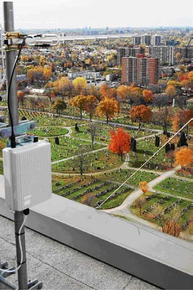
Abstract ……..

This report serves as the milestone nine as defined in the project: “Asymmetric Threat Mitigation in the
Great Lakes, St. Lawrence Seaway and Maritime Ports and Inshore Waters.” It documents a practical
field experimentation on the construction of a simple packet radio that operates over long distances and
uses existing Wi-Fi technology. The work innovates by using Wi-Fi constrained to 5 MHz bandwidth
over 700 MHz licensed spectral allocation, organized in a multi-hop mode as opposed to point-to-point or
point-multipoint fashion. This allows for a possible expansion towards a true mesh network for long-
distance packet radio. The system built connects CRC, via cameras, with two other sites: one 22 km to the
east, and the other 7 km to the west. The radio is energy efficient and transmits around 1.5 Mbps with
powers below 400 mW while consuming less than 7 W to operate each node. In remote locations it could
operate with a solar panel. CRC’s work is useful because it helps answer the question: what is the lowest
price and simplest system one can possibly assemble for a certain minimum broadband performance? By
modifying off-the-shelf Wi-Fi equipment this experiment was assembled for roughly $600. While this
low-cost surveillance solution is not a production model, but a research model, it well serves as a platform
for further research on many related topics such as: bit-rate performance of multi-hop systems versus
number of hops; system capacity issues in multi-hop and mesh radio configurations; RF interference
effects on the effective bit rate performance; multi-hop with frequency re-use; studies on the effect of
antenna mutual coupling per hop node and antenna polarization diversity applied in the wireless access
nodes.

DRDC CSS CR 2012-021
Résumé ….....

Ce rapport correspond à l'étape numéro neuf du projet: “Asymmetric Threat Mitigation in the Great
Lakes, St. Lawrence Seaway and Maritime Ports and Inshore Waters”. Il documente une expérience sur la
construction d'une radio à paquets qui fonctionne sur de longues distances en utilisant la technologie Wi-
Fi existante. Le travail innove en opérant avec une connexion Wi-Fi limitée à 5 MHz de bande passante
dans la bande spectrale de 700 MHz (sous licence), organisée en mode multi-noeuds, par opposition à un
système point à point ou point-multipoint. Cela permet une extension possible vers un réseau maillé pour
radio à paquets à longue distance. Le système construit relie CRC, via des caméras, avec deux autres
sites: un à 22 km à l'est de CRC et l'autre à 7 km à l'ouest de CRC. La radio est économe en énergie et
peut transmettre à un débit de 1,5 Mbps avec une puissance de transmission inférieure à 400 mW tout en
consommant moins de 7 W pour faire fonctionner chaque nœud; en régions éloignées, il pourrait donc
fonctionner avec un panneau solaire. Les travaux du CRC sont utiles car ils permettent de répondre à la
question: quel est le prix le plus bas et le système le plus simple qui peut être assemblé pour produire un
système capable d'accomplir un certain débit de transmission? En modifiant de l'équipement Wi-Fi
standard, ce système a été assemblé pour environ 600 $. Bien que cette solution de surveillance à faible
coût n'est pas un équipement de production, mais un prototype de recherche, il peut servir de plate-forme
pour de nouvelles recherches sur de nombreux sujets connexes tels que: la performance du système en
fonction du nombre de nœuds; les défis de capacité du système en fonction des configurations multi-
noeuds et de radios maillés ; les effets de brouillage RF sur les performances de débit; la réutilisation des
fréquences dans un système multi-noeuds; l'étude de l'effet de couplage mutuel des antennes et l'effet de
la diversité de polarisation des antennes pour les nœuds d'accès sans fil.

DRDC CSS CR 2012-021                                                                               ii
Executive Summary ……..

Practical Demonstration of a Low Cost − Long Range − Packet
Radio over 700 MHz Spectral Region
 The BTS-341 project general objectives were to evaluate security needs (gaps) and emerging
technologies to enhance persistent surveillance and small vessel detection, identification and tracking in
the Great Lakes, St. Lawrence Seaway, and maritime inshore waters and ports. The scope of the CRC
portion of the work was to propose an integrated wireless access solution for surveillance data traffic
serving the St. Lawrence Seaway border regions. The work output was to demonstrate, in practical field
experimentation, the basic hop network operating in 700 MHz band over long distances.

  CRC has been aware of the existence of long range WiFi, point-to-point systems, that were tested in
field experimentation over 20 to 30 km in several places around the world. The motivation for this work
was to innovate under the following conditions:

    •   This work innovates by using long distance WiFi constrained to 5 MHz bandwidth over 700 MHz
        licensed spectral allocation. Normally long-range WiFi uses point-to-point configurations with 20
        MHz signal bandwidth over unlicensed 2.4 GHz or 5.8 GHz carrier frequencies.

    •   The work uses long distance WiFi in a multi-hop mode as opposed to point-to-point or point-
        multipoint fashion. This allows the construction of a true mesh network for long distance packet
        radio.

This approach allows for a possible expansion towards a true mesh network for long-distance packet
radio.

The low-cost surveillance solution developed in this work is a prototype that can serve as a platform for
further research on many related topics such as: bit-rate performance of multi-hop systems versus number
of hops; system capacity issues in multi-hop and mesh radio configurations; RF interference effects on the
effective bit rate performance; multi-hop with frequency re-use; studies on the effect of antenna mutual
coupling per hop node and antenna polarization diversity applied in the wireless access nodes.

The spectrum of 700 MHz used for the experiments in this project has been allocated to Public Safety and
Security applications. Communications for Safety and Security are likely to be deployed in Canada under
the so called 4th generation of cellphone technology (also known as LTE − Long Term Evolution).
However, 700 MHz LTE systems are not commercial yet. The simple system deployed and demonstrated
in this work gives some insights as to what kind of services and performances one can expect to receive
from the much more complex and expensive LTE when it becomes available.

DRDC CSS CR 2012-021                                                                                iii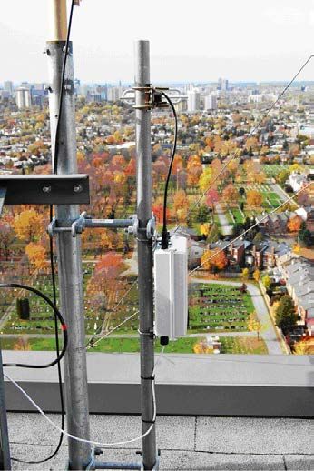
Sommaire ….....

Practical Demonstration of a Low Cost − Long Range − Packet
Radio over 700 MHz Spectral Region
  Les objectifs généraux du projet BTS 341 consistent à évaluer les besoins en sécurité (lacunes) et les
technologies émergentes pour améliorer la surveillance constante et la détection de petits navires, ainsi
que l’identification et la poursuite de cibles dans la Voie maritime des Grands Lacs et du Saint Laurent,
les ports maritimes et les eaux côtières. La partie des travaux réalisée par le Centre de recherches sur les
communications (CRC) vise à proposer une solution d’accès sans fil intégrée pour la surveillance du
trafic de données qui couvre les régions limitrophes de la Voie maritime du Saint Laurent. Ces travaux
visent à démontrer, dans le cadre d’une expérience pratique sur le terrain, le fonctionnement sur de
longues distances des réseaux à bonds de base dans la bande de 700 MHz.

 Le CRC connaît l’existence des systèmes point à point Wi Fi longue distance, qui ont été mis à l’essai au
cours d’expériences sur le terrain sur des distances de 20 à 30 km à plusieurs endroits dans le monde. Les
présents travaux visent à innover dans les conditions mentionnées ci-dessous.

•        Les présents travaux innovent en utilisant le Wi Fi longue distance limité à une largeur de bande
de 5 MHz sur les fréquences autorisées attribuées dans la bande de 700 MHz. En temps normal, le Wi Fi
longue distance utilise des configurations point à point avec une largeur de bande des signaux de 20 MHz
sur des fréquences porteuses non autorisées de 2,4 GHz ou de 5,8 GHz.

•       Pour les travaux, le Wi Fi longue distance est utilisé en mode à bonds multiples plutôt qu’en
mode point à point ou point à multipoint. Le mode utilisé permet la construction d’un véritable réseau
maillé pour les radiocommunications par paquets à longue distance.

La présente approche permet l’expansion vers un véritable réseau maillé pour les radiocommunications
par paquets à longue distance.

La solution de surveillance à faible coût mise au point dans le cadre des présents travaux est un prototype
qui peut servir de plateforme à d’autres recherches sur de nombreux sujets connexes, comme : le
rendement de débit binaire des systèmes à bonds multiples en fonction du nombre de bonds, les
problèmes de capacité du système en configuration radio maillée et à bonds multiples, les effets du
brouillage RF sur le rendement de débit binaire efficace, les bonds multiples avec réutilisation de
fréquences, les études des effets du couplage mutuel des antennes par nœud et la diversité de la
polarisation des antennes appliquée dans les nœuds d’accès sans fil.

La bande de 700 MHz utilisée pour réaliser les expériences du présent projet a été attribuée aux
applications de sûreté et de sécurité publique. De plus, les systèmes de communications aux fins de sûreté
et de sécurité seront sans doute déployés au Canada au moyen de la technologie cellulaire dite de
quatrième génération (aussi appelée LTE ou évolution à long terme). Les systèmes LTE dans la bande de
700 MHz ne sont toutefois pas encore offerts sur le marché. Par ailleurs, le système simple déployé et
démontré dans le cadre des présents travaux donne un aperçu du type de services et des performances
attendues pour un système LTE beaucoup plus complexe et coûteux, lorsque ce dernier sera disponible.

DRDC CSS CR 2012-021                                                                             iv
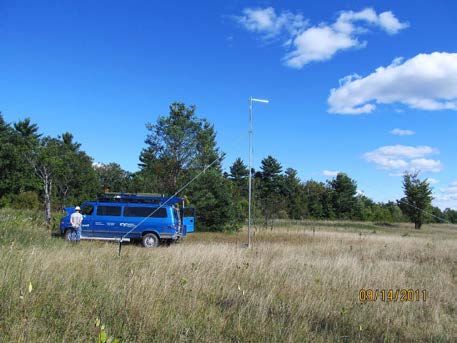
Table of contents

Abstract …….. .................................................................................................................................. i
Résumé …........................................................................................................................................ ii
Table of contents .............................................................................................................................. v
List of figures .................................................................................................................................. vi
List of tables................................................................................................................................... vii
Acknowledgements ....................................................................................................................... viii
1     Introduction ............................................................................................................................... 1
      1.1    Contribution of Milestone 9 ........................................................................................... 1
2     System Design − Methodology ................................................................................................. 2
3     Channelization Plan................................................................................................................... 5
      3.1  Narrowband and Broadband Interplay ........................................................................... 5
4     Assembling the Experiment ...................................................................................................... 7
      4.1  Planning the sites and Computing the Link Budget ....................................................... 7
      4.2  Network Access Node Firmware ................................................................................. 11
5     Performance .............................................................................................................................. 5
6     Transition and Exploitation ..................................................................................................... 16
7     Discussion of the Experiment and Perspectives Ahead .......................................................... 17
References ..................................................................................................................................... 19
Annex A Project Team ................................................................................................................ 21
List of symbols/abbreviations/acronyms/initialisms ...................................................................... 22

DRDC CSS CR 2012-021                                                                                                                                    v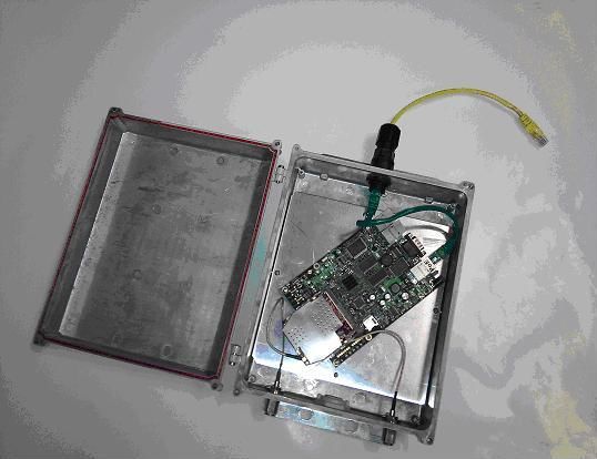
List of figures
Figure 1: Long distance backhaul. ................................................................................................... 2
Figure 2: Each node is a network access point. ............................................................................... 3
Figure 3: Commercial infrared and image sensors with WiFi connectivity. ................................... 3
Figure 4: Access node has few components and is easy to install. .................................................. 4
Figure 5: Channelization plan in the US for safety and security applications.. ............................... 5
Figure 6: Data aggregation. ......... .. . ....... .............. ...................................................................... 6
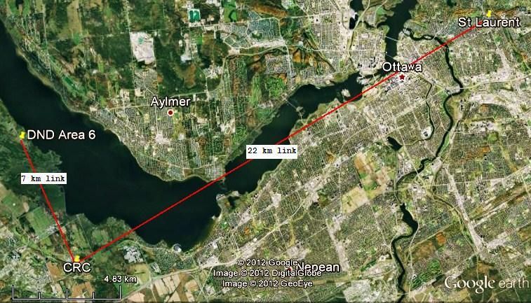
Figure 7: CRC to St. Laurent link is ~22 km long and CRC to DND Area 6 is ~7 km. .................. 8
Figure 8:View from the St. Laurent site with access node installed ~50m high.............................. 9
Figure 9: View from DND area−6 with the access node installed in a mast ~7 metres high. ........ 9
Figure 10: COVLAB shows the coverage from St. Laurent site to CRC. Signal level at CRC is
approximately −76 dBm for transmit power of +26 dBm (Copyright © by Industry Canada
1991−2007).................................................................................................................. 10
Figure 11: Network access node with 700 MHz port and 2.4 GHz WiFi hotspot. ........................ 11
Figure 12: Detail of the MikroTik router board (Copyright © Mikrotikls Ltd, 2000−2006)........ 12
Figure 13: The XR7−700 MHz WiFi radio (Copyright © 2011 by Ubiquiti Networks, Inc.). ...... 13
Figure 14: 700 MHz antenna (Copyright © 2005-2010 by ZDA Communications US LLC.). .... 13
Figure 15: Experiment with 3 access nodes including WiFi hotspot and video camera. ............... 15
DRDC CSS CR 2012-021 vi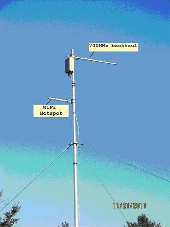
List of tables

Table 1: Data rate performance (average bit rate) ......................................................................... 16

DRDC CSS CR 2012-021                                                                                                             vii
Acknowledgements

This work was supported by Defence Research and Development Canada Centre for Security Science
Public Security Technical Program (PSTP 02-341BTS). The research manager of CRC/RBBW
(Broadband Wireless group) was John Sydor.

This report has been produced with the help of our many colleagues at CRC. Special thanks to the
Broadcast Technology Research branch that made available the use of the computer simulation tool
COVLAB which provided important results contained in this document. I thank the CRC/Manufacturing
group, specially Quince D’Angelo and Flamur Canaj for the construction of the antenna masts and other
mechanical parts that made the execution of this experiment possible. I thank the members of
CRC/RBBW group, specially Dr. David Roberts, Bernard Doray, Wayne Brett, Siva Palaninathan, Li Pan
and Larry Stone, all of them worked in this project from concept to execution towards its successful
conclusion. I thank the Department of National Defense – Connaught Range and Primary Training
Centre, Ottawa, for allowing us to place antennas in their facilities for the field experimentation. I thank
Gilles Gagnon and Robert Gagnon for the help and facilitation of the placement of antennas in test sites
coordinated by CRC/RTNT group. I thank CRC/RASN group and the valuable discussions with Dr. Petar
Djukic. I thank Pierre Meunier, portfolio manager of PSTP 02-341 project, for overall guidance and for
revising this work, and Dr. Alex Vukovic − CRC/VPTWS vice-president for supporting this research.

DRDC CSS CR 2012-021                                                                            viii
1       Introduction

  This report refers to the completion of Milestone 9 as defined in the project: “Asymmetric Threat
Mitigation in the Great Lakes, St. Lawrence Seaway and Maritime Ports and Inshore Waters”. The project
had CRC as the Federal Department Lead, with A.U.G. Signals Ltd, CFN Consultants, Blue Force Global
and AKW Global Enterprises in charge of executing the main project (PSTP Project No. 02-341 BTS).
The main project started on September 2010 and finished on June 2011 with Milestone 9 left to be
finished in a later date (December 2011).

 The BTS-341 project general objectives were to evaluate security needs (gaps) and emerging
technologies to enhance persistent surveillance and small vessel detection, identification and tracking in
the Great Lakes, St. Lawrence Seaway, and maritime inshore waters and ports. Within Milestone 9, the
scope of the CRC work was to propose an integrated wireless access solution for surveillance data traffic
serving the St. Lawrence Seaway border regions. The work output was to demonstrate, in a practical field
experimentation, the basic hop network operating in 700 MHz band over long distances.

 The reason why this report is detached from the main report of the BTS-341 project is because
Milestone 9 had an extended execution deadline particularly adjusted to accommodate the construction
and testing of hardware, software and the integration of the system for the field demonstration. This work
describes how this was achieved and show the results accomplished.

1.1      Contribution of Milestone 9
  CRC has been aware of the existence of long range WiFi, point-to-point systems, that were tested in
field experimentation over 20 to 30 km in several places around the world [1]. The motivation for this
work has never been to repeat a proven concept, but rather to innovate under the following conditions:

    •   This work innovates by using long distance WiFi constrained to 5 MHz bandwidth over 700 MHz
        licensed spectral allocation. Normally long-range WiFi uses point-to-point configurations with 20
        MHz signal bandwidth over unlicensed 2.4 GHz or 5.8 GHz carrier frequencies.

    •   The work uses long distance WiFi in a multi-hop mode as opposed to point-to-point or point-
        multipoint fashion. This allows the construction of a true mesh network for long distance packet
        radio.

 Besides the innovative aspects, Milestone 9 provided the Canadian R&D community involved in this
project with familiarization of 700 MHz bands and an understanding of the potential of cognitive radios
that may operate over UHF frequencies within TV white spaces [2]. Although Milestone 9 does not deal
directly with cognitive radios, it provides a platform for the development of hardware and software that
can be extended into TV vacant channels (where cognitive radio operation has been proposed).

 Finally, this work represents a low benchmark performance for long range WiFi systems. This is
because this system has been constructed with low-cost, off-the-self, components and it is very simple to
assemble and operate. The spectrum of 700 MHz used for the experiments in Milestone 9 has been
allocated to Public Safety and Security applications. Communications for Safety and Security are likely to
be deployed in Canada under the so called 4th generation of cellphone technology (also known as LTE −
Long Term Evolution). However, 700 MHz LTE systems are not commercial yet. The simple system
deployed and demonstrated in this work gives some insights as to what kind of services and performances

DRDC CSS CR 2012-021
one can expect to receive from the much more complex and expensive LTE when it becomes available.
CRC work is useful because it helps to answer the question: what is the lowest price and simplest system
one can possibly assemble for a certain minimum broadband performance? This benchmark data will help
personnel with test systems in advance of the Long-Term Evolution (LTE) procurements, thus educating
Public Safety of the capabilities they can expect from suppliers when procuring high-end communications
in the very near future.
2 System Design − Methodology
This work has been centred in the construction of an experimental radio network prototype which
followed guidelines that are important for surveillance. The scenario was motivated in the data traffic for
the surveillance of the St. Laurence Seaway border region. Some of the key conditions were: must be a
wireless access system able to expand into a full mesh network; must form a network with inexpensive
wireless access nodes; must be energy efficient and consume low power; must be easy to install and
maintain and must be a long-range packet radio system. These conditions are explained in more detail as
follows:
° Monitoring over long distances:
consider the example of surveillance
from Montreal to Kingston with almost
300 km of shoreline. Data centres
indicated as (A) and (B) in Figure 1
would be responsible for aggregating the
sensor data collected alongside the
Seaway. Thus, sensor data gathered along
the Seaway might travel distances as far
as 150 km in order to reach the nearest
collection facility centre. This calls for a
radio system designed for long-range
backhaul capability.
Figure 1: Long distance backhaul.
° Efficiency and low cost: a long-range system needs to have a low maintenance characteristic in order
to reduce its operational costs. Energy efficiency is also required. Our demonstration radio prototype
consumes little energy (i.e. produces less heat, no special cooling needed). One desired feature is the
possibility of using solar energy as the source of electrical power for the radios. These principles
resulted in a prototype composed of two small electronic boards of low cost, placed inside an
aluminum case with cables and antennas.
° Scalable to a full mesh network: the mesh network is fault tolerant in the sense that if the current
communication data path breaks then there is the possibility for the data to switch and travel through
a different route. Moreover, each node is an access point for the remote sensors of the network
(Figure 2). Using this guidance our demonstration prototype started with three nodes, and each node
acts as a relay as well as an access point to the network.
DRDC CSS CR 2012-021 2access points and relays
image
sensor
Figure 2: Each node is a network access point.
° Easy installation and operation: the prototype weighs less than 2 kg with the antenna. It takes a single
cable of the type RJ-45 (Ethernet cable) that connects the radio with a laptop (for system
configuration) and a car battery that supplies electricity to the system. The cable also provides
network access to computers. Finally, the WiFi connection links a sensor to the network. Note the
sensors are equipped with WiFi transceivers. A commercial example of such WiFi enabled sensor is
shown in Figure 3. The basic network access node is illustrated in Figure 4.
Axis
Foscam Canada
AverMedia
Figure 3: Commercial infrared and image sensors with WiFi connectivity.
DRDC CSS CR 2012-021 3ACCESS
NODE
700 MHz
WiFi long-range backhaul
access
SENSOR
equipped with
WiFi Power over Ethernet
RJ-45 cable
Ethernet
RJ-45 cable
laptop for system
configuration
Figure 4: Access node has few components and is easy to install.
A battery of 12V feeds the access node by the same cable which allows for a laptop connection and
system configuration. Inside the access node box there is one 2.4 GHz WiFi router that gives connectivity
to the wireless sensors. This feature forms a hot-spot area with about 100 metres in radius around the
access node. Finally, the 700 MHz antenna forms the backhaul that links this node with other nodes in the
system (i.e. hop network or mesh configuration).
DRDC CSS CR 2012-021 43 Channelization Plan
The frequency plan used for the demonstration is:
• 760.5 – 765.5 MHz, centre frequency at 763 MHz (part of old TV channel 62 & 63)
• 771.0-776.0 MHz, centre frequency at 773.5 MHz (part of old TV channel 64).
In the US, the spectrum allocation for public safety and security uses a different plan as shown in Figure
5. The USA Federal Communications Commission − FCC [3] designated the frequencies: 763-768 MHz
and 793-798 MHz for broadband communications. FCC also designated the frequencies of: 769-775 MHz
and 799-805 MHz for narrowband applications. Furthermore, the narrowband segments are partitioned
into 960 channels each with 6.25 kHz of allocated bandwidth. How this impacts the task of monitoring is
the subject of analysis of the next sub-item.
763 MHz 768 769 MHz 775
Broadband
high speed data 960 channels of low speed
data (6.25 kHz/channel)
793 MHz 798 799 MHz 805
Broadband
high speed data 960 channels of low speed
data (6.25 kHz/channel)
Figure 5: Channelization plan in the US for safety and security applications..
3.1 Narrowband and Broadband Interplay
The construction of a long-range wireless solution for sensor connectivity must fit within a
channelization structure, particularly if Canada opts for a frequency plan as in Figure 5. A good solution
explores both broadband and narrowband resources in order to render sensor data to a central location.
DRDC CSS CR 2012-021 5Each sensor in the network may operate
in ON/OFF fashion, that is, perform only
during an interval over a certain period.
After the ON/OFF period is computed
Access Node
S
then an upper limit for the aggregate
effective bandwidth of the access node can backhaul
sensor S
be calculated. This is done in a narrowband
preliminary form by a simple formula: N S sensor
× b × t / T, where t/T is the time ON/OFF
for the sensor, b is the sensor bit rate and S
N is the number of sensors per node.
sensor 64 kbps
A numerical example clarifies the
scenario: a commercial off-the-self camera
is capable of recording with a resolution
of 640 per 480 pixels per frame. It may
Concentrator
take 15 to 30 frames per second and use
broadband
an image compression technique such as
narrowband
MPEG4. This requires roughly 64 kbps of
data bandwidth (high-end cameras may narrowband
require up to 300 kbps). In 10 seconds the
camera will acquire 150 frames and will
produce 640 kbits of data [4]. Data
recording and transmission is set to 10
seconds ON and 50 seconds OFF. Figure 6 – Data aggregation
Therefore, in this example, the effective
bit rate would be (10/60)×(64k) = 10.67 kbps. This will require two channels of the narrowband portion
of the spectrum allocated to Safety and Security in order to forward data from that sensor.
The analysis may be expanded to include an overhead due to the wireless transmission protocols. A
typical overhead is around 30% to be added to the computation. Another factor to consider is the air-
interface interval between data packets. In a packet radio there may be an average of 10% of idle interval
between consecutive transmit packets (for example, in 100 ms period there may be 90 ms actually
occupied by an RF carrier in the air interface). This idle interval between packets is normally random and
has an average that is a function of the firmware. Moreover, sensor data may be carried out in one-way
fashion (i.e. traffic from sensor to central controller without feedback as in UDP packets) which increases
the system capacity. In fact sensor data is commonly a one-way communication.
Finally, several narrowband channels may be multiplexed by a concentrator and the final aggregate is
forwarded by a broadband channel.
DRDC CSS CR 2012-021 64 Assembling the Experiment
4.1 Planning the sites and Computing the Link Budget
The demonstration of the long range 700MHz − WiFi @ 5MHz bandwidth required a detailed study of
the electromagnetic propagation characteristics of the terrain around Ottawa, ON. With the propagation
study in hand we were able to plan the location of the sites for the access nodes of the network.
The method selected for the coverage prediction was via computer simulation. CRC-COVLAB® V 3.0
Coverage Prediction and Analysis Software [5] was the tool used for the computations. COVLAB is a
professional software package that has been employed by commercial radio and TV broadcast stations
across the world.
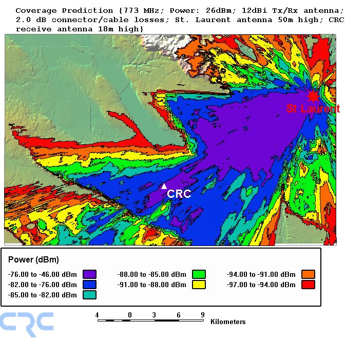
The sites that were finally chosen were 22 km to the east of CRC, and the other 7 km to the north as
shown in Figure 7 − Figure 9. Moreover, the computer simulation by COVLAB provided results for
receive powers under a service availability of 95% (see Figure 10).
The final system proved to be energy efficient. The radios transmit around 1.5 Mbps with powers below
400 mW while consuming less than 7 W to operate each node. In remote locations the node could operate
with a solar panel. Other parameters used in the computation of the link budget include:
• Tx plus Rx cable/connector losses: 2 dB
• Tx and Rx antenna: ZDA Communications, model ZDADJ750-14G, measured antenna gain at
anechoic chamber (CRC): 12 dBi; crosspol: −20dB; beamwidth ~42o (azimuth plain). Tx and Rx
antenna height: St. Laurent site (50 m); CRC site (18 m).
• Azimuth orientation St. Laurent to CRC: 239o.
• Operation: carrier frequency of 773.000 MHz, signal bandwidth of 5 MHz, digital signal.
• Transmit power: 26 dBm over 5 MHz.
• Receiver noise figure: 6 dB.
• Terrain: land cover data base by GeoBase (Canadian Council on Geomatics) − National Capital
Region and elevation by U.S. Geological Survey data base.
DRDC CSS CR 2012-021 7Figure 7: CRC to St. Laurent link is ~22 km long and CRC to DND Area 6 is ~7 km. DRDC CSS CR 2012-021
Figure 8 -View from the St. Laurent site with access node installed ~50m high.

     Figure 9 -View from DND area−6 with the access node installed in a mast ~7 metres high.

DRDC CSS CR 2012-021
Figure 10 –COVLAB shows the coverage from St. Laurent site to CRC. Signal level at CRC is approximately −76 dBm for transmit power of +26 dBm (Copyright © by Industry Canada 1991−2007). DRDC CSS CR 2012-021
4.2 Network Access Node Firmware
power over Ethernet, network access and configuration
router board
1st 700 MHz antenna
700 MHz transceiver
2.4 GHz antenna
2st 700 MHz antenna
Figure 11 –Network access node with 700 MHz port and 2.4 GHz WiFi hotspot.
The network access node is composed of:
• Weather resistant aluminium box equipped with gasket and sealed outdoor connectors. There are
three connectors (see Figure 11): one power
over Ethernet cable that is used also for 700 MHz port 1 700 MHz port 2
system configuration and as a network access
port.
Network
Node
• RF cards: the router board can be fitted with
up to 3 RF cards. Figure 11 shows an upper configuration
& power
slot containing one 700 MHz transceiver.
Below that there is a middle slot with one RF
card supporting the access for 2.4 GHz WiFi
devices. The lower slot supports a second WiFi 2.4 GHz
700 MHz transceiver. port 3
• Router board: is the motherboard for the RF slots. Its function is to route TCP/IP packets to and
from anyone of the four ports. Note the in/out ports 1, 2 and 3 are RF ports while port 4 is an
Ethernet port with standard cable RJ45.
– The Router Board
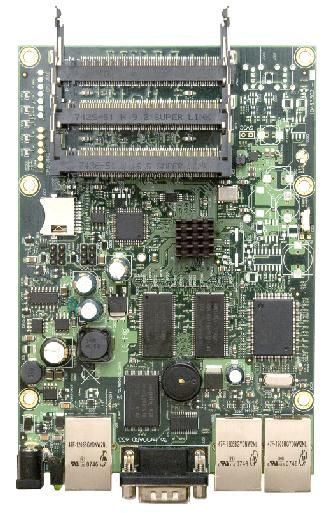
DRDC CSS CR 2012-021Figure 12 – Detail of the MikroTik router board (Copyright © Mikrotikls Ltd, 2000−2006).
Details of the router board are shown in Figure 12 with three RF slots. The board manufacturer is
Mikrotik, model RB433AH Router. It was chosen due to its characteristics which comprise:
• MIPS-based AR7100 processor with 300 MHz clock.
• Has 128 MB of internal RAM and 64 MB of flash memory.
• 3 Ethernet ports of which 1 port is PoE (power over Ethernet) and Auto MDI/X
• 1 serial port (configuration and debugging)
• 3 miniPCI slots (were RF cards are connected).
– The 700 MHz Radio Transceiver Card
DRDC CSS CR 2012-021Figure 13 – The XR7−700 MHz WiFi radio (Copyright © 2011 by Ubiquiti Networks, Inc.).
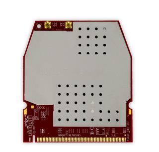
A picture of the 700 MHz WiFi radio is in Figure 13. The transceiver manufacturer is Ubiquiti, model
XR7. It has some key features useful this experiment:
• Works with 4 RF channels located between 763 − 778 MHz.
• Protocol derived from 802.11 b/g MAC and translated to 700 MHz band.
• The 700 MHz air interface transmits with a signal bandwidth that is 5 MHz wide as opposed to 20
MHz of traditional WiFi. Thus, it compresses the original WiFi spectrum.
• Uses miniPCI interface compatible with the router board from Microtik.
Our XR7 radio cards were tested and presented a maximum transmit packet power of +26 dBm for
signals with 5 MHz bandwidth at 763 MHz.
– The 700 MHz Antenna
The 700 MHz antenna, from ZDA Communications, model ZDADJ750-14YG, had its radiation pattern
measured in the CRC anechoic chamber where it showed a maximum gain of 12 dBi, ~42o beam width,
and cross-polarization rejection of ~20dB.
The manufacturer specified the antenna operation within the range 746−806 MHz.
Figure 14 – 700 MHz antenna (Copyright © 2005-2010 by ZDA Communications US LLC.).
List of Software Modules
All software used were Open Source. The list of software ported into the nodes includes:
• Open WRT Linux.
DRDC CSS CR 2012-021• Modified MadWiFi Drivers.
• IPERF for throughput tests.
5 Performance
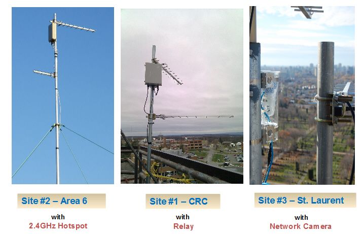
Figure 15 shows the network access nodes that were used for the practical demonstration during autumn
2011 in Ottawa.
A video camera was installed at St. Laurent site, marked as “site #3” in
Figure 15. The camera captured live video from the St. Laurent area and streamed the video through an
Ethernet port (yellow cable, port 4, in Figure 11). The video data was routed by the Mikrotik board to the
700 MHz XR7 card. The signal was then amplified to +26 dBm and transmitted with a carrier of 773
MHz towards CRC, shown as site #1 in
DRDC CSS CR 2012-021Figure 15.
Site #1 is a network node with two 700 MHz antennas. One antenna points to site #3 and the other to site
#2. The node relayed video data from site #3 (St. Laurent) to site #2 (DND Area 6). This relay was of the
type “store and forward” so that there was an excess latency in the process of decoding the video packets
from St. Laurent and encoding it again before forwarding it to Area−6. This store-and-forward method
was the simplest to implement and presented one of the lowest performances amongst other types of relay
methods. The result represented a low benchmark performance as far as latency in relay is concerned. The
node #1 also worked as an access point (via port 4 of the Mikrotik router) which gave access to the
network for a laptop located in a CRC laboratory.
Figure 15 – Experiment with 3 access nodes including WiFi hotspot and video camera.
DRDC CSS CR 2012-021Site #2 (Area−6) had two antennas: an upper antenna for the 700 MHz channel and another, at lower
height, for the WiFi 2.4 GHz hotspot access point. The 700 MHz antenna pointed to CRC site #1 while
the 2.4 GHz antenna pointed to a trail road in the fields around area−6 test site at a DND facility. At site
#2 one laptop gained access to the network via port 3 (see Figure 11) using 2.4 GHz wireless link. From
there, the Mikrotik board routed the signal to the 700 MHz port. Conversely, video data from St. Laurent
was relayed by node #1 (CRC) and node #2 where it was delivered to the laptop connected by the WiFi
hotspot at Area−6.
Bit-rate performance, obtained via IPERF, was as follows:
Table 1: Data rate performance (average bit rate)
to
Site #1 Site #2 Site #3
from
Site #1 1.6 Mbps 1.3 Mbps
Site #2 1.6 Mbps 639 kbps
Site #3 1.4 Mbps 631 kbps
6 Transition and Exploitation
DRDC CSS CR 2012-021As a demonstration project this experiment has no commercial value. It uses OpenSource software that is free and can be downloaded from the Internet (i.e. Open WRT Linux, IPERF, etc.). Its low cost (around $600 for all three nodes assembled) allows other departments to assemble similar networks and test theoretical or simulation results with practical field verification for their models. CRC/Industry Canada does not claim any intellectual property in this Open system. It functions as a low benchmark performance for VHF packet radios. 7 Discussion of the Experiment and Perspectives Ahead One noticeable result of this experiment was the maximum bit rate of 1.6 Mbps attained in the hop between Site #1 and Site #2 (7 km apart). While reasonably high, this performance number is somewhat lower that the theoretical bounds [6]. One explanation for this lower performance is the slow speed of the Mikrotik router that serves the transmit buffer of TCP/IP packets. The processor is slow in serving the transmit buffer while packets fill in quickly. While the buffer is full it slows down in the TCP/IP packet flow which decreases the bit rate performance. This problem appears not to be associated with the air interface (RF 700 MHz channel) and a solution would come by increasing the router board handling capabilities. The performance amongst Site #1, #2 and #3 appears to be symmetrical for downlink and uplink. The average bit rate from Site #1−> #3 and from Site #3−> #1 are 1.3 and 1.4 Mbps respectively and this proximity suggests a symmetric link (in a statistical sense). Unfortunately, no records were taken that allows us to compute standard deviation or other statistics. Statistical analysis for this link may be performed in subsequent research. Another result of interest was the decrease in bit rate by approximately one half from 1.4 Mbps (Site #3−> 1) to 631 kbps (Site #3−> 2) when the dataflow passed through the CRC relay node (double hop). A future experiment could test if the bit rate decreases by half whenever the flow passes by any other relay node. In other words, future work needs to verify if speed performance decreases by one third in triple- hop, by one fourth in quadruple-hop, etc. A theoretical reason may exist to explain this observation but was not researched in this project. Analysis of the latencies for packets from Site #3−> 1 and Site #1−> 2 and Site #3−> 2 would be a good addition in the road map of extra tests that can be exercised using this network in future. This experimental setup allowed for the study of capacity issues. For instance, one could test the decrease in system capacity against interference and noise. This experiment also allowed for another test of special importance which was the possibility of deploying the system with frequency re-use. That is, one could employ the frequency channel 773 MHz to transmit signals from Site #3−> 1 and then re-use that same channel in the relay from Site #1−> 2. How RF interference would affect the system performance if CRC relay node had used the same frequency channel to receive video from Site #3 and relay it to Site #2 is a point to be investigated. Studies of capacity as function of the number of devices that compete for access per node was also possible in our experimental network (note configuration presented had only two users which were the video camera placed at Site #3 and a laptop at Site #2). This could open another research topic: “what would be the bit rate performance as a function of the number of devices, per node, trying to get access to the network?”. Many other case studies appeared while we developed this radio platform, including the effects of polarization diversity versus system performance. Note that the present system used the same horizontal polarization in both antennas in all nodes. Also observe that both 700 MHz antennas at Site #1 were placed orthogonal to each other. What would be the effect of antenna mutual coupling and RF interference if the antennas were placed in different orientation with respect to one another? DRDC CSS CR 2012-021
Evidently, the list of research topics is large involving the matter of VHF long-range packet radios. The
experimental setup presented in this document also aimed to help those engaged in theoretical and
simulation studies that need field validation or practical model verification. Our network proved to have a
simple setup, had low cost, and components were readily available off-the-self.

DRDC CSS CR 2012-021
References

[1] Chebrolu K., Raman B. and Sen S., Long−Distance 802.11b Links: Performance Measurements and
Experience, MobiCom ’06, Los Angeles, USA, September 23-26, 2006.
[2] Nekovee M., Cognitive Radio Access to TV White Spaces: Spectrum Opportunities, Commercial
Applications and Remaining Technology Challenges, Symposium on New Frontiers in Dynamic
Spectrum, 6-9 April, 2010, Singapore, pp. 1-10.
[3] Federal Communication Commission − FCC (2011), 700 MHz Public Safety Band, URL:
http://transition.fcc.gov/pshs/public-safety-spectrum/700-MHz/safetyband.html, retrieved on Jan. 2012.
[4] GeoVision, IP cameras, URL: http://www.geovision.com.tw/english/cal_webcam_test1-5.asp ,
retrieved on Jan. 2012.
[5] Communications Research Centre, Coverage Prediction and Analysis Software, URL:
http://www.crc.gc.ca/en/html/crc/home/info_crc/publications/technology_showcase/covlab, retrieved on
Jan. 2012.
[6] Jun J., Peddabachagari P., Sichitiu M, Theoretical Maximum Throughput of IEEE 802.11 and its
Applications, Proceedings of the Second IEEE International Symposium on Network Computing and
Applications (NCA’03), May 2003, pp.249-256.

DRDC CSS CR 2012-021
This page intentionally left blank.

DRDC CSS CR 2012-021
Annex A             Project Team

The PSTP 02-341 BTS project has the following organigram

PORTFOLIO MANAGER
Name : Pierre Meunier
Title : Portfolio Manager, Surveillance, Intelligence & Interdiction
Phone : 613-944-4367
Email : pierre.meunier@drdc-rddc.gc.ca

LEAD FEDERAL DEPARTMENT
Department: Communications Research Centre Canada, Industry Canada
Name: Dr. Andre Brandao
Phone: 613-998-8585
Email: andre.brandao@crc.gc.ca
Website: http://www.crc.gc.ca

OTHER PROJECT PARTICIPANTS
Organization: A.U.G. Signals Ltd. (Lead industry partner)
Contact Individual: Tatyana Litvak
Phone: 416-923-4425, ext. 235
Email: litvak@augsignals.com
Website: http://www.augsignals.com

Organization: Blue Force Global
Contact Individual: Serge Vidalis
Phone: 778-426-2604
Email: svidalis@blueforceglobal.com
Website: http://www.blueforceglobal.com

Organization: CFN Consultants
Contact Individual: John Leggat
Phone: (613) 232-1576
Email: jleggat@cfncon.com
Website: http://www.cfnconsultants.com/

Organization: AKW Global Enterprises Inc.
Contact Individual: Albert Wong
Phone: (416) 301-9909
Email: albert@akwglobal.com
Website: http://www.lampo.com/AKW/index.html

MILESTONE #9 Experiment (this document) of PSTP 02-341 BTS
Department: Communications Research Centre Canada, Industry Canada
Branch: Terrestrial Wireless Systems − VPTWS
Group: Broadband Wireless − RBBW
Contact: John Sydor, Manager
Phone: 613-998-2388
Email: john.sydor@crc.gc.ca

DRDC CSS CR 2012-021
List of symbols/abbreviations/acronyms/initialisms

CRC      Communications Research Centre
DND      Department of National Defence
DRDC     Defence R&D Canada
FCC      Federal Communications Commission
LTE      Long Term Evolution
MAC      Media Access Control
MDI/X    Media Dependent Interface
MPIS     Microprocessor without Interlocked Pipeline Stage
PSTP     Public Security Technical Program
RF       Radio Frequency
TCP/IP   Transmission Control Protocol/Internet Protocol
UDP      User Datagram Protocol
VHF      Very High Frequency

DRDC CSS CR 2012-021
DOCUMENT CONTROL DATA
      (Security classification of title, body of abstract and indexing annotation must be entered when the overall document is classified)
1.    ORIGINATOR (The name and address of the organization preparing the document.                   2.    SECURITY CLASSIFICATION
      Organizations for whom the document was prepared, e.g. Centre sponsoring a                           (Overall security classification of the document
      contractor's report, or tasking agency, are entered in section 8.)                                   including special warning terms if applicable.)

      Defence R&D Canada – CSS                                                                             Unclassified
      222 Nepean St                                                                                        (NON-CONTROLLED GOODS)
      Ottawa, Ontario K1A 0K2                                                                              DMC A
                                                                                                           Review: ECL June 2012
3.    TITLE (The complete document title as indicated on the title page. Its classification should be indicated by the appropriate abbreviation (S, C or U)
      in parentheses after the title.)

      Practical Demonstration of a Low Cost − Long Range − Packet Radio over 700 MHz Spectral Region

4.    AUTHORS (last name, followed by initials – ranks, titles, etc. not to be used)

      Dr. André L. Brandão
5.    DATE OF PUBLICATION                                                          6a.   NO. OF PAGES                   6b.       NO. OF REFS
      (Month and year of publication of document.)                                       (Total containing information,           (Total cited in document.)
                                                                                         including Annexes, Appendices,
                                                                                         etc.)
      March 2012                                                                                     29                                       6
7.    DESCRIPTIVE NOTES (The category of the document, e.g. technical report, technical note or memorandum. If appropriate, enter the type of report, e.g.
      interim, progress, summary, annual or final. Give the inclusive dates when a specific reporting period is covered.)

      Contract Report
8.    SPONSORING ACTIVITY (The name of the department project office or laboratory sponsoring the research and development – include address.)

      Defence R&D Canada – CSS
      222 Nepean St
      Ottawa, Ontario K1A 0K2
9a.   PROJECT OR GRANT NO. (If appropriate, the applicable research and            9b.   CONTRACT NO. (If appropriate, the applicable number under
      development project or grant number under which the document                       which the document was written.)
      was written. Please specify whether project or grant.)

      PSTP 02-341BTS                     3782-2011-32cj
10a. ORIGINATOR'S DOCUMENT NUMBER (The official document                           10b. OTHER DOCUMENT NO(s). (Any other numbers which may be
     number by which the document is identified by the originating                      assigned this document either by the originator or by the sponsor.)
     activity. This number must be unique to this document.)

      DRDC CSS 2012-021
11.   DOCUMENT AVAILABILITY (Any limitations on further dissemination of the document, other than those imposed by security classification.)

      Unclassified
12.   DOCUMENT ANNOUNCEMENT (Any limitation to the bibliographic announcement of this document. This will normally correspond to the
      Document Availability (11). However, where further distribution (beyond the audience specified in (11) is possible, a wider announcement
      audience may be selected.))

       Unlimited

     DRDC CSS CR 2012-021
13. ABSTRACT (A brief and factual summary of the document. It may also appear elsewhere in the body of the document itself. It is highly
desirable that the abstract of classified documents be unclassified. Each paragraph of the abstract shall begin with an indication of the
security classification of the information in the paragraph (unless the document itself is unclassified) represented as (S), (C), (R), or (U). It
is not necessary to include here abstracts in both official languages unless the text is bilingual.)
Abstract ……..
This report serves as the milestone nine as defined in the project: “Asymmetric Threat Mitigation in
the Great Lakes, St. Lawrence Seaway and Maritime Ports and Inshore Waters.” It documents practical
field experimentation on the construction of a simple packet radio that operates over long distances
and uses existing Wi-Fi technology. The work innovates by using Wi-Fi constrained to 5 MHz
bandwidth over 700 MHz licensed spectral allocation, organized in a multi-hop mode as opposed to
point-to-point or point-multipoint fashion. This allows for a possible expansion towards a true mesh
network for long-distance packet radio. The system built connects CRC, via cameras, with two other
sites: one 22 km to the east, and the other 7 km to the west. The radio is energy efficient and transmits
around 1.5 Mbps with powers below 400 mW while consuming less than 7 W to operate each node. In
remote locations it could operate with a solar panel. CRC’s work is useful because it helps answer the
question: what is the lowest price and simplest system one can possibly assemble for a certain
minimum broadband performance? By modifying off-the-shelf Wi-Fi equipment this experiment was
assembled for roughly $600. While this low-cost surveillance solution is not a production model, but a
research model, it well serves as a platform for further research on many related topics such as: bit-rate
performance of multi-hop systems versus number of hops; system capacity issues in multi-hop and
mesh radio configurations; RF interference effects on the effective bit rate performance; multi-hop
with frequency re-use; studies on the effect of antenna mutual coupling per hop node and antenna
polarization diversity applied in the wireless access nodes.
Résumé ….....
Ce rapport correspond à l'étape numéro neuf du projet: “Asymmetric Threat Mitigation in the Great
Lakes, St. Lawrence Seaway and Maritime Ports and Inshore Waters”. Il documente une expérience
sur la construction d'une radio à paquets qui fonctionne sur de longues distances en utilisant la
technologie Wi-Fi existante. Le travail innove en opérant avec une connexion Wi-Fi limitée à 5 MHz
de bande passante dans la bande spectrale de 700 MHz (sous licence), organisée en mode multi-
noeuds, par opposition à un système point à point ou point-multipoint. Cela permet une extension
possible vers un réseau maillé pour radio à paquets à longue distance. Le système construit relie CRC,
via des caméras, avec deux autres sites: un à 22 km à l'est de CRC et l'autre à 7 km à l'ouest de CRC.
La radio est économe en énergie et peut transmettre à un débit de 1,5 Mbps avec une puissance de
transmission inférieure à 400 mW tout en consommant moins de 7 W pour faire fonctionner chaque
nœud; en régions éloignées, il pourrait donc fonctionner avec un panneau solaire. Les travaux du CRC
sont utiles car ils permettent de répondre à la question: quel est le prix le plus bas et le système le plus
simple qui peut être assemblé pour produire un système capable d'accomplir un certain débit de
transmission? En modifiant de l'équipement Wi-Fi standard, ce système a été assemblé pour environ
600 $. Bien que cette solution de surveillance à faible coût n'est pas un équipement de production,
mais un prototype de recherche, il peut servir de plate-forme pour de nouvelles recherches sur de
nombreux sujets connexes tels que: la performance du système en fonction du nombre de nœuds; les
défis de capacité du système en fonction des configurations multi-noeuds et de radios maillés ; les
effets de brouillage RF sur les performances de débit; la réutilisation des fréquences dans un système
multi-noeuds; l'étude de l'effet de couplage mutuel des antennes et l'effet de la diversité de polarisation
des antennes pour les nœuds d'accès sans fil.
14. KEYWORDS, DESCRIPTORS or IDENTIFIERS (Technically meaningful terms or short phrases that characterize a document and could be
helpful in cataloguing the document. They should be selected so that no security classification is required. Identifiers, such as equipment
model designation, trade name, military project code name, geographic location may also be included. If possible keywords should be
selected from a published thesaurus, e.g. Thesaurus of Engineering and Scientific Terms (TEST) and that thesaurus identified. If it is not
possible to select indexing terms which are Unclassified, the classification of each should be indicated as with the title.)
Packet radio; Wi-Fi technology; 700 MHz
DRDC CSS CR 2012-021Vous pouvez aussi lire