Twin Pour 30 - Lancer Worldwide
←
→
Transcription du contenu de la page
Si votre navigateur ne rend pas la page correctement, lisez s'il vous plaît le contenu de la page ci-dessous
Original Instructions
                                                                                                        Twin Pour 30
                                                                                                        LANCER INSTALLATION GUIDE
                                                                                                                                    Model TP30

FOR QUALIFIED INSTALLER ONLY. This basic Installation Sheet is an initial release. If a complete Operations
Manual (for the unit being installed) is required or needed, please refer to the Lancer website (lancerworldwide.com)
for immediate access, or for your convenience, scan this QR code with a mobile device for immediate access to oth-
er Technical Documents and alternative translations (if available) pertaining to this unit. Contact Lancer Customer
Service for assistance as required.
ABOUT THIS MANUAL                                                           BEFORE GETTING STARTED
This booklet is an integral and essential part of the product and           Each unit is tested under operating conditions and is thoroughly
should be handed over to the operator after the installation and            inspected before shipment. At the time of shipment, the carrier
preserved for any further consultation that may be necessary.               accepts responsibility for the unit. Upon receiving the unit,
Please read carefully the guidelines and warnings contained                 carefully inspect the carton for visible damage. If damage exists,
herein as they are intended to provide the user with essential              have the carrier note the damage on the freight bill and file a
information for the continued safe use and maintenance of the               claim with carrier. Responsibility for damage to the dispenser lies
product. In addition, it provides GUIDANCE ONLY to the user on              with the carrier.
the correct services and site location of the unit.
   The installation and relocation, if necessary, of this product must be carried out by qualified personnel with
   up-to-date safety and hygiene knowledge and practical experience, in accordance with current regulations.

IMPORTANT SAFETY INSTRUCTIONS
   ! Intended Use
  The dispenser is for indoor use only. This unit is not a toy. Children should be supervised not to play with appliance. It should not be
  used by children or infirm persons without supervision. This appliance can be used by children aged from 8 years and above and
  persons with reduced physical, sensory or mental capabilities or lack of experience and knowledge if they have been given supervi-
  sion or instruction concerning use of the appliance in a safe way and understand the hazards involved. Cleaning and user mainte-
  nance shall not be performed by children without supervision. The min/max ambient operating temperature for the dispenser is 40°F
  to 90°F (4°C to 32°C). Do not operate unit below minimum ambient operation conditions. Should freezing occur, cease operation of
  the unit and contact authorized service technician. Service, cleaning and sanitizing should be accomplished only by trained person-
  nel. Applicable safety precautions must be observed. Instruction warnings on the product being used must be followed.

   ! Utilisation prévue
  La distributrice doit être utilisée à l’intérieur uniquement. Cet appareil n’est pas un jouet. Ne laissez pas les enfants jouer avec l’appareil.
  Cet appareil ne doit pas être utilisé par des enfants ou des personnes handicapées sans supervision. Cet appareil peut être utilisé par
  des enfants âgés de 8 ans et plus et des personnes ayant des capacités physiques, sensorielles ou mentales réduites ou un manque
  d’expérience et de connaissances s’ils ont reçu une supervision ou des instructions concernant l’utilisation de l’appareil en toute sécurité
  et comprennent les risques. impliqué. Le nettoyage et l’entretien journalier ne doivent pas être effectués par des enfants sans supervision.
  La température ambiante de fonctionnement de la distributrice se situe entre 40 °F et 90 °F (4 °C et 32 °C). Ne faites pas fonctionner
  l’appareil sous la température ambiante minimale. Si l’appareil a gelé, cessez de l’utiliser et contactez un technicien d’entretien autorisé.
  Le personnel assigné au nettoyage, à la désinfection et à l’entretien de l’appareil doit avoir reçu une formation à cet effet. Les mesures de
  sécurité en vigueur doivent être suivies. Observez toutes les étiquettes de sécurité apposées sur l’appareil.

                                                                                                                          Lancer PN:28-3089
                                                                                                                  Revision: 00-0, 11/18/2020
F Electrical Warning
Check the dispenser name plate label, located behind the splash plate, for the correct electrical requirements of unit. Do not plug
into a wall electrical outlet unless the current shown on the serial number plate agrees with local current available. Follow all local
electrical codes when making connections. Each dispenser must have a separate electrical circuit. Do not use extension cords with
this unit. Do not ‘gang’ together with other electrical devices on the same outlet. Do not locate multiple portable socket-outlets or
portable power supplies at the rear of the appliance. The key-switch does not disable the line voltage to the transformer primary.
Always disconnect electrical power to the unit to prevent personal injury before attempting any internal maintenance. The
resettable breaker switch should not be used as a substitute for unplugging the dispenser from the power source to service the
unit. Only qualified personnel should service internal components of electrical control housing. Make sure that all water lines are
tight and units are dry before making any electrical connections!

    F Avertissement - Électricité
Reportez-vous à l’étiquette d’identification de la distributrice située derrière la plaque antiéclaboussures pour connaître les caractéristiques
électriques de l’appareil. Ne branchez pas l’appareil dans une prise électrique murale à moins que le courant disponible corresponde à l’in-
tensité nominale indiquée sur l’étiquette portant le numéro de série. Les raccordements électriques doivent être conformes au code élec-
trique local. Chaque distributrice doit être branchée dans un circuit électrique dédié. Ne raccordez pas cet appareil à l’aide d’une rallonge
électrique. Ne branchez pas cet appareil dans une prise électrique multiple partagée par d’autres appareils. Ne placez pas plusieurs prises
d’alimentation multiples portables ou alimentations électriques portables à l’arrière de l’appareil. L’interrupteur verrouillable ne désactive
pas la tension de ligne au primaire du transformateur. Débranchez toujours l’alimentation électrique de l’appareil avant une intervention
d’entretien afin de prévenir des blessures. L’ouverture du disjoncteur à réarmement ne remplace pas le débranchement de la distributrice
au moment de procéder à une intervention d’entretien. Seul le personnel qualifié est autorisé à faire l’entretien et la réparation des compo-
sants électriques logés dans le boîtier du module de commande. Veillez à ce que les conduites d’eau soient étanches et que l’appareil soit
sec avant de procéder à des raccordements électriques.

    5 Carbon Dioxide (CO2)
•     WARNING: Carbon Dioxide (CO2) is a colorless, noncombustible gas with a light pungent odor. High percentages of CO2 may
      displace oxygen in the blood.
•     WARNING: Prolonged exposure to CO2 can be harmful. Personnel exposed to high concentrations of CO2 gas will experience
      tremors which are followed by a loss of consciousness and suffocation.
•     WARNING: If a CO2 gas leak is suspected, immediately ventilate the contaminated area before attempting to repair the leak.
•     WARNING: Strict attention must be observed in the prevention of CO2 gas leaks in the entire CO2 and soft drink system.

    5 Dioxyde de carbone (CO2)
•     AVERTISSEMENT : Le dioxyde de carbone (CO2) est un gaz incolore et non combustible qui a une odeur âcre. Un pourcentage élevé de
      CO2 réduit la quantité d’oxygène dans le sang.
•     AVERTISSEMENT : L’exposition prolongée au CO2 est dangereuse pour la santé. Le personnel exposé à un taux élevé de CO2 souffre de
      tremblements qui sont suivis par une perte de conscience et la suffocation.
•     AVERTISSEMENT : Si vous suspectez une fuite de CO2, aérez immédiatement la zone contaminée avant de procéder à la réparation de la fuite.
•     AVERTISSEMENT : Il est impératif de prévenir toute fuite de CO2 dans le système de distribution de CO2 et de breuvage.

    ! Automatic Agitation
Units are equipped with an automatic agitation system and will activate unexpectedly. Do not place hands or foreign objects in the
ice bin. Unplug the dispenser during servicing, cleaning, and sanitizing. To avoid personal injury, do not attempt to lift the dispenser
without assistance. For heavier dispensers, use a mechanical lift.

    ! Agitation automatique
Chaque unité dispose d’un système automatique d’agitation qui peut se mettre en marche subitement. Éviter de placer les mains ou
des objets étrangers dans le bac à glaçons. Débrancher le distributeur avant l’entretien, le nettoyage et l’aseptisation. Pour éviter toute
blessure, ne pas tenter de soulever le distributeur sans aide. Utiliser un élévateur mécanique pour les distributeurs plus lourds.

    ! Warning
All power circuits must be disconnected before accessing the connection terminals.

    ! Avertissement
Avant d’accéder aux bornes de raccordement, tous les circuits d’alimentation doivent être déconnectés

2
! Water Notice
 Provide an adequate potable water supply. Water pipe connections and fixtures directly connected to a potable water supply must
 be sized, installed, and maintained according to federal, state, and local laws. The water supply line must be at least a 3/8 inches
 (9.525 mm) pipe with a minimum of 25 psi (0.172 MPa) line pressure, but not exceeding a maximum of 50 psi (0.345 MPa).
 Water pressure exceeding 50 psi (0.345 MPa) must be reduced to 50 psi (0.345 MPa). Use a filter in the water line to avoid equip-
 ment damage and beverage off-taste. Check the water filter periodically, as required by local conditions. The water supply must
 be protected by means of an air gap, a backflow prevention device or another approved method to comply with NSF standards. A
 leaking inlet water check valve will allow carbonated water to flow back through the pump when it is shut off and contaminate the
 water supply. Ensure the backflow prevention device complies with ASSE and local standards. It is the responsibility of the installer
 to ensure compliance.

  ! Remarque relative à l’eau
 Assurez-vous que l’alimentation en eau potable est suffisante. Les branchements et les raccords de tuyauterie d’eau directement reliés à
 l’alimentation en eau potable doivent avoir la taille appropriée et être installés et entretenus conformément aux codes provincial et local.
 La conduite d’alimentation en eau doit avoir un diamètre minimum de 3/8 po (9,525 mm) et une pression minimale de 25 psi (0,172 Mpa)
 sans toutefois excéder 50 psi (0,345 Mpa). Si la pression d’eau excède 50 psi (0,345 Mpa), réglez le régulateur de pression à 50 psi
 (0,345 Mpa). Inspectez le filtre à eau régulièrement, selon les conditions du réseau local. Le circuit d’alimentation en eau doit être protégé
 au moyen d’un clapet antiretour, ou d’un dispositif antirefoulement ou d’une autre méthode conforme aux normes de la NSF. Dans le cas
 d’une fuite du clapet antiretour de la conduite d’alimentation, l’eau gazéifiée refoule à travers la pompe (lorsqu’elle n’est pas en service) et
 contamine ainsi l’alimentation en eau. Assurez-vous que le dispositif antirefoulement est conforme aux normes de l’ASSE et aux codes en
 vigueur localement. Cette tâche est de la responsabilité de l’installateur.

SPECIFICATIONS & FEATURES
DIMENSIONS                                  ELECTRICAL                                          CARBON DIOXIDE (CO2) SUPPLY
   Width: 30.0 inches (762 mm)                   115 VAC / 60 Hz / 5.0 Amps                          Min Pressure: 70 psi (0.483 MPa)
   Depth: 34.25 inches (869.95 mm)
                                                                                                     Max Pressure: 80 psi (0.552 MPa)
   Height: 40.6 inches (1031.24 mm)         CARBONATED WATER SUPPLY
                                                 Min Flowing Pressure: 25 psi (0.172 MPa)       FITTINGS
WEIGHT                                           Max Static Pressure: 50 psi (0.345 MPa)
                                                                                                     Carbonator Inlet: 3/8 inch barb
   Shipping: 290 lbs (132 kg)                                                                        Plain Water Inlet: 3/8 inch barb
   Operating (w/ Ice): 570 lbs (259 kg)     PLAIN WATER SUPPLY                                       Brand Syrup Inlets: 3/8 inch barb
   Ice Capacity: 280 lbs (127 kg)                Min Flowing Pressure: 75 psi (0.517 MPa)            Ambient Flavor Inlets: 3/8 inch barb
                                                                                                     CO2 Inlet: 3/8 inch barb

                                           This unit emits a sound pressure level below 70 dB
  READ THIS MANUAL
 This manual was developed by the Lancer Worldwide as a reference for the owner/operator and installer of this
 dispenser. Please read this guide before installation and operation of this dispenser. If service is required please call your
 Lancer Service Agent or Lancer Customer Service. Always have your model and serial number available when you call.

  VEUILLEZ LIRE CE MANUEL
 Ce manuel élaboré par Lancer Worldwide est un outil de référence à l’intention des propriétaires, utilisateurs et installateurs de
 cette distributrice. Veuillez lire ce manuel avant d’installer et d’utiliser cet appareil. Pour l’entretien, communiquez avec le service
 à la clientèle de Lancer ou avec un technicien autorisé. Ayez sous la main le numéro de série et le modèle de distributrice lors de
 votre appel.

        Your Service Agent:

        Service Agent Telephone Number:

        Serial Number:

        Model Number:
INSTALLATION
Unpack the Dispenser                                                          NOTE
1.   Set shipping carton upright on the floor then cut package               NSF listed units must be sealed to the counter.
     banding straps and remove.
2.   Open top of carton and remove interior packaging.                        NOTE
3.   Lift carton up and off of the unit.                                     Toute unité homologuée NSF doit être scellée sur le
                                                                             comptoir.
4.   Remove plywood shipping base from unit by moving unit so
     that one side is off the counter top or table allowing access
     to screws on the bottom of the plywood shipping base.              5.   Select a location for the remote pump deck, syrup pumps,
                                                                             CO2 tank, syrup containers, and water filter (recommended).
      NOTE                                                              6.   Cut out required opening for the water, syrup, and CO2 lines
     If unit is to be transported, it is advisable to leave the              in the designated dispenser location.
     unit secured to the plywood shipping base.
                                                                              Leveling the Dispenser:
      REMARQUE                                                               In order to facilitate proper dispenser drainage, ensure
     Si l’appareil doit être transporté, il est conseillé de le lais-        that the dispenser is level, front to back and side to
     ser fixé sur la base d’expédition en contreplaqué.                      side. Place a level on the top of the rear edge of the
                                                                             dispenser. The bubble must settle between the level
5.   Remove accessory kit and loose parts from ice compartment.              lines. Repeat this procedure for the remaining three
                                                                             sides. Level unit if necessary. For optimum perfor-
6.   Clean ice chute and ice bin using cleaning instruction on               mance place the unit at a 0° tilt. The maximum tilt is 5°.
     page 20.

      NOTE                                                                    Mise à niveau de la distributrice
     Inspect unit for concealed damage. If evident, notify                   Afin de faciliter une vidange complète, assurez-vous que
     delivering carrier and file a claim against the same.                   l’appareil est de niveau sur les axes avant arrière et gauche
                                                                             droit. Placez un niveau sur le bord arrière de la distribu-
                                                                             trice. La bulle doit se situer entre les deux lignes. Répétez
      REMARQUE                                                               la procédure sur les trois autres côtés. Ajustez le niveau de
     Inspectez l’appareil pour déceler des dommages cachés.                  l’appareil si nécessaire. Pour un résultat maximal, réglez
     Si l’appareil est endommagé, avisez le transporteur et                  l’inclinaison à 0°. L’inclinaison maximale est de 5°.
     soumettez-lui une réclamation.

Selecting/Preparing Counter Location                                          NOTE
                                                                             To ensure that beverage service is accessible to all
1.   Select a level, well ventilated location that is in close               customers, Lancer recommends that counter height
     proximity to a properly grounded electrical outlet, within five         and equipment selection be planned carefully. The
     (5) feet (1.5 m) of a drain, a water supply that meets the              2010 ADA Standards for Accessible Design states that
     requirements shown in the Specifications section found on               the maximum reach height from the floor should be no
     page 3, and away from direct sunlight or overhead lighting.             more than 48” if touch point is less than 10” from the
2.   Sufficient clearance must be provided, if an ice maker is not           front of the counter, or a maximum of 46” if the touch
     installed, to allow filling ice compartment from a five gallon          point is more than 10” and less than 27” from the front
     bucket (a minimum of 16 inches is recommended).                         of the counter. For more information about the
                                                                             customer’s legal requirements for the accessibility of
3.   The selected location should be able to support the weight of
                                                                             installed equipment, refer to 2010 ADA Standards for
     the dispenser, ice and possibly an icemaker being installed
                                                                             Accessible Design - http://www.ada.gov.
     after counter cut out is made. Total weight (with icemaker) for
     this unit could exceed 800 pounds (363.6kg).
                                                                              REMARQUE
      NOTE                                                                   Pour s’assurer que le service de boissons est acces-
     Lancer does NOT recommend the use of shaved or                          sible à tous les clients, Lancer recommande que la
     flake ice in the dispenser.                                             hauteur du comptoir et le choix de l’équipement soient
                                                                             soigneusement planifiés. Les normes ADA 2010 pour
                                                                             la conception accessible stipulent que la hauteur de
      NOTE                                                                   portée maximale depuis le sol ne doit pas dépasser 48
     Lancer recommande de ne PAS utiliser de glace pilée ou                  pouces si le point de contact est à moins de 10 pouces
     de glace en écailles avec le distributeur.                              de l’avant du comptoir, ou un maximum de 46 pouces
                                                                             si le point de contact est plus à 10 ”et à moins de 27”
                                                                             de l’avant du comptoir. Pour plus d’informations sur les
4.   Unit may be installed directly on counter-top. Once installed           exigences légales du client concernant l’accessibilité
     directly on the counter, unit must be sealed to the count-              des équipements installés, reportez-vous aux normes
     er-top with an FDA approved sealant.                                    ADA 2010 pour la conception accessible -
                                                                             http://www.ada.gov.
 4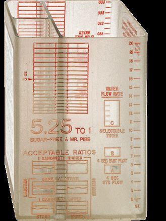
! ATTENTION
Installing an Icemaker (if necessary)                                           Failure to use an ice bin thermostat will not only void
    ! ATTENTION                                                                 your IBD’s warranty but will result in the inability to
                                                                                control the level of ice in the ice bin which can cause
       When installing an icemaker on the dispenser, use a
                                                                                damage to your dispenser.
       bin thermostat to control the ice level (see below). This
       will prevent damage to the dispensing mechanism. The
       bracket for mounting a thermostat is located in the ice                   ! ATTENTION
       bin. During the automatic agitation cycle and while
                                                                                En plus d’annuler la garantie de l’IBD, l’absence de
       dispensing ice, ensure there is adequate space
                                                                                thermostat dans le bac à glaçons rend impossible le
       between the top of the ice level and the bottom of the                   contrôle du niveau de glaçons dans le bac, ce qui peut
       icemaker so the ice can move without obstruction.                        endommager le distributeur.
       Contact your icemaker manufacturer for information
       on a suitable bin thermostat.
                                                                           5.   Ensure the icemaker is installed properly to allow for opening
                                                                                of the Merchandiser.
        ! ATTENTION
                                                                           6.   Ensure manual fill is accessible.
       Si une machine à glaçons est installée sur le distributeur,
       utiliser un thermostat pour contrôler le niveau de glaçons          7.   Clean and maintain icemaker per manufacturer’s
       dans le bac (voir ci-dessous). Cela évitera d’endommager                 instructions.
       le mécanisme de distribution. Le support de fixation du
       thermostat se trouve dans le bac à glaçons. Durant le
       cycle d’agitation automatique et lors de la distribution            Dispenser Installation
       des glaçons, veiller à ce que l’espace soit suffisant entre
       le dessus de l’amas de glaçons et le bas de la machine à
                                                                               NOTE
       glaçons, de sorte que le déplacement des glaçons se fasse                The installation, and relocation if necessary, must
       sans obstruction. Contacter le fabricant de la machine à                 be carried out by qualified personnel with up-to-date
       glaçons pour connaître les thermostats appropriés.                       knowledge and practical experience, in accordance
                                                                                with current regulations.

1.     Install the icemaker per manufacturer specifications. Points
       of consideration include drainage, ventilation, and drop
                                                                                 NOTE
       zones.                                                                   L’installation, et la réinstallation s’il y a lieu, doivent
                                                                                être effectuées par du personnel qualifié disposant de
2.     An adapter plate is required when installing an icemaker.
                                                                                connaissances actuelles et cumulant une expérience
       Contact your Sales Representative or Lancer Customer                     pratique, conformément à la réglementation en vigueur.
       Service for more information.
3.     A bin thermostat is required in order to control the level of ice
                                                                           1.   To open the merchandiser, pull out and up.
       in the dispenser (Refer to ATTENTION above). Contact your
       icemaker manufacturer to obtain the correct bin thermostat.
4.     Bin thermostat should be a minimum of 2” below the top
       edge of the dispenser. The preferred location of the bin
       thermostat is on the left side wall.
     Attach Bin Stat Bracket As Shown   Recommended Bin Stat Attachment
                                              Bulb           Tube

                       4”
                                                                                                                                              A

                                                                                                                                     B

                                                                                                                           A. Merchandiser
                                                                                                                           B. Splash Plate
                                                                           2.   To remove the splash plate, first remove cup rest and sneeze
                                                                                guard. Then remove splash plate.
                                                                           3.   Route appropriate tubing from the water source to the water
                                                                                inlet at the remote pump deck.

                                                                                                                                              5
4.   If necessary, install water booster (Lancer PN MC-163172)
                                                                       9.   Insert and install carbonator probe.
     between water supply and the remote pump deck.
5.   Using tubing cutters, cut the water line and install U-fitting
     then route appropriate tubing from the U-fitting to the plain
     water inlet at the unit.

                               C     A. Line to Water Source
                D
                                     B. U-Fitting
                                     C. Line to Remote Pump Deck
                                     D. Line to Plain Water Inlet

                                                     A

                         B
6.   Route appropriate tubing from the syrup pump location to the
     syrup inlets and connect tubing to all syrup inlets.
                                                                       10. Route appropriate tubing from the CO2 source location to the
                                                                           CO2 inlet on the unit and connect tubing to inlet.
                                                                       11. Route the power supply cord to a grounded electrical outlet
                                                                           of the proper voltage and amperage rating.

 C
                                                                             F WARNING
                                                                            DO NOT PLUG UNIT INTO GROUNDED ELECTRICAL
                                                                            OUTLET AT THIS TIME. Make sure that all water lines
                                                                            are tight and unit is dry before making any electrical
                                                                            connections
 A                                                 A. Oetiker Pliers
                                                   B. Tubing
                                                   C. Syrup/Water            ! MISE EN GARDE
     B                                                Inlet                 À CE STADE, NE PAS BRANCHER L’UNITÉ DANS UNE
                                                                            PRISE SECTEUR DE TERRE. Veiller à ce que l’ensemble
                                                                            des canalisations d’eau soient fixées solidement et que
7.   Route appropriate tubing from the remote pump deck outlet
                                                                            l’unité soit bien sèche avant d’effectuer des branchements
     to the carbonated water inlet at unit.
                                                                            électriques.
                                             A. Remote Pump Deck
                                    C        B. Pump Inlet             12. Route drain hose from designated open type drain to fitting
 A                                           C. Pump Outlet                on Drip Tray and connect hose to fitting. (if applicable)
                                             D. Line to Carb Inlet
                                                                                                                        A. Drain Fitting
                                                                                                                   C
                                                                                                                        B. Drain Line
                                                                                                                        C. Drip Tray

                                                         D

                B                                                                           A       B
8.   Install a shut-off valve in the water line feeding the remote
     pump deck as well as the water line feeding the plain water
     inlet.
         NOTE
     See Plumbing Diagrams on page 26 for reference.

         REMARQUE
     Voir les schémas de plomberie à l’avant de l’unité ou à
     la page 26 pour référence.

 6
! CAUTION                                                     14. Install condensation fan on the underside of the unit by (1)
                                                                       pushing fan bracket into slots in the right wall, then (2) sliding
    Drain line must be insulated with a closed cell                    down to engage.
    insulation. Insulation must cover the entire length of
    the drain hose, including fittings. The drain should be
    installed in such a manner that water does not collect
    in sags or other low points, as condensation will form.
                                                                                                                  2
     ! AVERTISSEMENT
    La conduite de récupération doit être isolée à l’aide d’un
    isolant à cellules closes. L’isolant doit recouvrir toute la
    longueur du tuyau de vidange, y compris les raccords. Le
    drain doit être installé de sorte que l’eau ne s’accumule
    pas dans les creux ni les points bas afin d’éviter toute
                                                                                                            1
    condensation.

     ! ATTENTION                                                   15. Connect the unit’s red and black power harness to
    Pouring hot water into drain may cause the Drain                   fan connector.
    Tube to collapse. Allow only luke warm or cold water           16. Reattach Drip Tray and Cup Rest to unit.
    to enter Drain Tube. Pouring coffee tea and similar
    substances into drain may cause the Drain Tube to                   NOTE
    become clogged with coffee or tea grounds, or other
    solid particles.                                                   When installing the drip tray, make sure both of the
                                                                       cold plate drain boots are lined up to the opening in
                                                                       the drip tray. Make sure the end of the boots rests at
     ! ATTENTION                                                       least a half of an inch over the edge of the opening to
    Le tube de vidange peut s’affaisser si de l’eau chaude s’y         ensure proper drainage of the cold plate.
    écoule par le drain. Permettre uniquement l’écoulement
    d’eau tiède ou froide dans le tube de vidange. La décharge
    de café, de thé ou de substances similaires dans le drain           REMARQUE
    peut bloquer le tube de vidange.                                   Lors de l’installation du bac collecteur, assurez-vous
                                                                       que les deux tuyaux de vidange de la plaque froide
Condensation Fan Installation                                          sont alignés avec les ouvertures du bac collecteur. As-
                                                                       surez-vous que l’extrémité du tuyau repose à au moins
13. Attach fan bracket to fan assembly using screws provided.
                                                                       un demi-pouce sur le bord de l’ouverture pour assurer
                                                                       un drainage adéquat de la plaque froide.

                                                                                                                                     7
Installing CO2 Supply
                                                                      5.   Connect tubing routed from the tee at the syrup pumps to the
1.   Connect high pressure CO2 regulator assembly to CO2                   second low pressure regulator.
     cylinder or bulk system.

         ! ATTENTION
                                                                                                                         C
     Before installing regulator, ensure that a seal (washer
     or o-ring) is present in regulator attachment nut.

         ! ATTENTION
     Avant d’installer le détendeur, veiller à ce que l’écrou de
     montage du détendeur soit muni d’un joint d’étanchéité
     (rondelle ou joint torique).                                                                            A. Line to Dispenser
                                                                                                  D          B. Line to Syrup Pumps
                                                                               A
                                                                                              B              C. Line to CO2 Regulator
                                                                                                             D. CO2 Regulator Manifold
            A
                                 C
                                                                               ! ATTENTION
                                                                           A dedicated CO2 regulator is required to supply the CO2
                                                                           inlet at the unit as well as to all syrup pumps.

                                                           D                   ! ATTENTION
                                                                           Un régulateur de CO2 dédié est nécessaire pour alimenter
                                                                           l’entrée de CO2 à l’unité ainsi qu’à toutes les pompes à
           B
                                                                           sirop.

                                                  A. CO2 Regulator    6.   Using a wrench, loosen lock nut on the regulator adjustment
     -    Thread regulator nut on to tank, then   B. Outlet                screw of the high pressure CO2 regulator connected to the
          tighten nut with wrench                 C. Wrench                source, then using a screwdriver back out lock nut screw all
                                                  D. CO2 Supply            the way.
2.   Connect a 1/4” nut, 3/8” stem and seal to CO2 regulator                   ! WARNING
     outlet.
                                                                           DO NOT TURN ON CO2 SUPPLY AT THIS TIME
A. CO2 Regulator
B. Wrench                                                      A
C. 1/4” nut, Stem
                                                                               ! MISE EN GARDE
D. CO2 Supply                                                              NE PAS OUVRIR L’ALIMENTATION EN CO2 À CE STADE.

                                                                                                        A. CO2 Regulator
               B
                                                    D                                                   B. Screwdriver
                                                                                                        C. Regulator Adjustment Screw
                                                                           A
                                                      C                                                          B

3.   Route appropriate tubing from the low pressure CO2
     regulator manifold location to the 1/4” nut, 3/8” stem on the
     high pressure CO2 regulator attached to source and connect
                                                                                                                C
     tubing.
4.   Connect tubing routed from the CO2 inlet at the unit to one of
     the low pressure CO2 regulator manifold outlets.                 7.   Repeat Step 6 for both low pressure CO2 regulators on the
                                                                           regulator manifold routed to the unit and the syrup pumps.

 8
Dispenser Setup 6. Turn on the power to the dispenser by pressing the on/off
1. Turn on water source. toggle button on the right side of the unit electrical box and
2. Open the pressure relief valve located on the front of the turning the 3-way keyswitch to the vertical position.
unit, by flipping up on the valve cap lever. Hold open until
water flows from the relief valve then close (flip down) the
relief valve.
A
A. Dispenser Power
On/Off
7. Test the ice dispense feature by ensuring that the ice auger
runs when ice lever is pressed.
8. If necessary, turn on the screen by pressing the power sup-
ply toggle buttons on the left side of the unit electrical box.
9. Once the screen has booted up, the service menu for drink
3. Verify all Bag-In-Box contains syrup and check all
setup must be accessed.
connections for leaks.
10. Access the Service Menu by turning the keyswitch clock-
4. Place enough ice in the ice bin to fill approximately 1/2 of the
wise to the third position.
bin before plugging in the unit.
5. Connect unit power cord to grounded electrical outlet.
F WARNING
The dispenser must be properly electrically grounded
to avoid serious injury or fatal electrical shock. The
power cord has a three-prong grounded plug. If a Sleep Position On Position Service Position
three-hole grounded electrical outlet is not available,
use an approved method to ground the unit. Follow 11. A keypad will appear, enter the designated pin number to
all local electrical codes when making connections. access the service menu.
Each dispenser must have a separate electrical circuit. 12. For technician access to service menu, repeat step 10 and
Do not use extension cords. Do not connect multiple enter the technician’s pin number (4433).
electrical devices on the same outlet.
13. For manager’s access to the service menu, repeat step 10
and enter the manager’s pin number (6655).
! MISE EN GARDE 14. For access to only the Sold Out Menu, repeat step 10 and
Le distributeur doit être mis à la terre de manière adéquate enter the Sold Out pin (963.).
pour éviter toute blessure grave et décharge électrique
fatale. Le cordon d’alimentation dispose d’une fiche à
trois broches mise à la terre. En l’absence d’une prise
électrique à trois conducteurs mise à la terre, employer
une méthode approuvée pour assurer la mise à la
terre de l’unité. Respecter les exigences du code de
l’électricité local au moment d’effectuer des branchements
électriques. Chaque distributeur doit disposer d’un circuit
électrique distinct. Ne pas utiliser de cordon prolongateur.
Ne pas brancher d’autres appareils électriques dans la
même prise de courant.
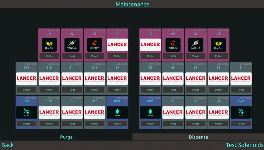
9NOTE REMARQUE
The technician’s access to the service menu allows Une fois la purge activée, elle continuera à distribuer
access to the following menus: System, Lighting, Sold le produit jusqu’à ce qu’elle soit désactivée. Pour
Out, Time & Delays, Valve Configurations, Maintenance, désactiver la purge, appuyez simplement à nouveau
Data Management, Component Versions, Test Solenoids. sur le bouton Purge. Jusqu’à quatre modules peuvent
être purgés à la fois. Une fois que quatre modules sont
REMARQUE sélectionnés, tous les autres modules sont grisés et ne
peuvent pas être sélectionnés.
L’accès du technicien au menu de service permet
d’accéder aux menus suivants: Système, Éclairage,
Épuisé, Temps et délais, Configurations des vannes, 18. Once a steady flow of water is achieved, tap the Purge but-
Maintenance, Gestion des données, Versions des com- ton again to deactivate the modules.
posants, Solénoïdes de test 19. Make sure the pump deck is turned OFF before turning on
CO2.
NOTE 20. Turn on CO2 at the source then, using a screwdriver, adjust
The manager’s access to the service menu allows the high pressure regulator at the source to 110 psi (0.758
access the Sold Out screen, and the Time & Delays MPa) then tighten locknut with wrench.
screen.
B A. Regulator Adjustment Screw
B. Adjust to 110 psi (0.758 MPa)
REMARQUE C. Wrench
L’accès du gestionnaire au menu de service permet A
accéder à l’écran Sold Out et à l’écran Time & Delays.
15. From the service menu tap the Maintenance button.
C
21. Adjust both of the low pressure regulators on the regulator
manifold to 75 psi (0.517 MPa) then tighten locknut with
wrench.
22. Activate each soda module until gas-out.
23. Plug in the remote carbonator pump deck, if not already
done so, and turn the switch to the ON position.
24. Activate each soda module until the carbonator pump comes
16. Tap the Purge tab at the bottom of the screen. on. Release the button, allow carbonator to fill and stop.
17. Tap the Purge buttons for both the plain water and the car- Repeat this process until a steady flow of carbonated water
bonated water modules. is achieved.
NOTE
The pump deck has a 3 minute timeout feature. If the
timeout occurs, turn the deck OFF then ON by flipping
the switch on the control box.
NOTE
Un délai d’inactivité de 3 minutes est prévu pour le bloc de
pompes. Si ce délai est dépassé, mettre le bloc de pompes
à ARRÊT, puis à MARCHE à l’aide de l’interrupteur de la
boîte de commande.
NOTE
NOTE To check for CO2 leaks, close the valve on the CO2
Once the purge is activated, it will continue to dispense cylinder and observe if the pressure to the system
product until it is deactivated. To deactivate the purge, drops with the cylinder valve closed for five minutes.
simply tap the Purge button again. Up to four modules Open the cylinder valve after check.
can be purged at one time. Once four modules are
selected, all other modules are grayed out and
cannot be selected.
10NOTE NOTE
Pour vérifier la présence de fuite de CO2, fermer la valve Each brand has a default water type and ratio already
de la bouteille de CO2 pour déterminer si la pression du set when they are selected. The water type and ra-
système chute dans un délai de cinq minutes. tio can be adjusted if necessary. Adjust the ratio by
Ouvrir la valve de la bouteille après la vérification. tapping “Use Custom Ratio“, and entering the new
value on the keypad.
25. Activate each valve to purge air from the syrup lines.
REMARQUE
Adding New Brand/Flavor Modules Chaque marque a un type d’eau et un rapport par
1. In order to use a brand or flavor module, the module must défaut déjà définis lorsqu’ils sont sélectionnés. Le type
first be configured. et le rapport d’eau peuvent être ajustés si nécessaire.
2. From the Service menu, tap the Valve Configuration Ajustez le rapport en appuyant sur “Utiliser le rapport
button. personnalisé” et en entrant la nouvelle valeur sur le
clavier.
6. Once a brand/flavor has been selected for a corresponding
module, tap the back button on the lower left corner to return
to the Valve Configuration Screen.
7. Repeat Steps 3 and 5 for any of the other brand or flavor
modules.
8. Tap the Back button to return to the Service menu.
3. From the Valve Configuration menu, tap any brand or flavor
module to open its Configuration Page.
9. From the Service Menu, tap the Maintenance button.
10. Tap the Purge tab at the bottom of the screen.
11. Purge any new brand or flavor module until there is a steady
flow of syrup. (See previous page)
4. Tap the “Brand“ or “Flavor“ tab at the top of the screen to set
the selected valve as a brand or flavor.
5. Select a brand group from the Available Brands column. The
list of available brands will change to reflect what’s in the
group you selected. Tapping on a brand icon will select it for
the valve being configured.
12. Tap the Back button to return to the Service Menu.
11CALIBRATION & MAINTENANCE
Calibrating Plain/Carbonated Water Modules
1. From the Service menu, tap the Valve Calibration button. NOTE
2. Tap the Calibrate on the Water Valve to be calibrated. The larger the volume dispensed, the more accurate
the results.
REMARQUE
Plus le volume distribué est grand, plus les résultats
sont précis.
6. With a graduated cylinder or ratio cup placed in a position
below the nozzle, tap the Purge button. The unit will dis-
pense the volume designated in the previous step.
3. From the Valve Calibration screen enter a water flow rate
value of 73.93 ml/sec using the slider. (This is roughly 2.5 fl
oz/sec, which is normal for 3.0 fl oz/sec finished drink )
Fill to 200 ml
4. Set the Timer to the ON position and select Volume as the
desired unit of measurement. Ratio Cup
Graduated Cylinder *Not Included
7. Examine the dispensed volume in the graduated cylinder. If
the dispensed volume does not match the value entered on
the screen in step 5, use a screwdriver to adjust the
plain water flow control.
C
A
5. Using the slider, enter 200 ml to be dispensed. The provided
graduated cylinder or ratio cup will be used to calibrate the
plain and carbonated water module. Increase Decrease
A. Flow Control
B. Valve Retainer
D B C. Solenoid
D. Valve Body
8. See Plumbing Diagram on front of machine or page 26 for
reference.
9. Repeat steps 6 and 7 until the designated volume is
achieved.
10. Repeat calibration for the other water modules.
12Calibrating Brand Syrup Modules - Using a Graduated Cylinder
NOTE NOTE
Ensure there is ice on the cold plate and the lines are The water flow rate was set to 73.93 ml/sec, which
cold before attempting to set the flow rates on the makes the final syrup flow rate 14.79 ml/s. The finished
valves. The drink temperature should be no higher drink flow rate dispensed will be 88.72 ml/s.
than 40°F (4.4°C) when flow rates are set.
REMARQUE REMARQUE
Le débit d’eau a été réglé à 73,93 ml/s, ce qui fait que le
Assurez-vous qu’il y a de la glace sur la plaque froide
débit de sirop final est de 14,79 ml/s. Le débit de bois-
et que les conduites sont froides avant de tenter de
son fini distribué sera de 88,72 ml/s.
régler les débits sur les vannes. La température de la
boisson ne doit pas dépasser 40 ° F (4,4 ° C) lorsque
les débits sont réglés. 5. With the graduated cylinder placed in a position below the
nozzle, tap the Purge button. The unit will
dispense the designated syrup amount.
1. From the Service menu, tap the Valve Calibration button.
2. Tap the Calibrate on the Syrup Valve to be calibrated.
Fill to 50 ml
3. Set the Timer to the ON position and select Volume as the
desired unit of measurement.
4. Using the slider, enter in an amount of 50 ml as the
preset dispensing amount. Graduated Cylinder
6. Examine the dispensed volume in the graduated cylinder.
If the dispensed volume does not match the value of 50 ml,
use a screwdriver to adjust the brand syrup flow control.
(See Plumbing Diagram on page 26 for reference).
C
A
Increase Decrease
A. Flow Control
D B. Valve Retainer
B
C. Solenoid
D. Valve Body
7. Repeat steps 5 and 6 until the designated volume of 50 ml is
achieved.
8. Repeat steps 2 - 6 for the remaining brand syrup modules.
13Calibrating Brand Syrup Modules - Using a Syrup Separator
NOTE 7. Using the slider, enter 5 seconds as the dispense time.
A syrup separator is included with every machine for
use with a Ratio Cup to set the brand module flow
rates. A Ratio Cup is not included with the machine.
REMARQUE
Un séparateur de sirop est inclus avec chaque machine
pour une utilisation avec un Ratio Cup pour régler les
débits du module de marque. Un Ratio Cup n’est pas
inclus avec la machine.
8. Hold the ratio cup under the separator and turn it for the best
1. After calibrating water valves, remove the nozzle cover by visibility, then push the “Start Dispense” button.
squeezing sides and pulling down.
2. Remove nozzle by twisting counterclockwise and pulling
NOTE
downward. Ensure the “W” section is in the water section of the
ratio cup.
REMARQUE
Assurez-vous que la section “W” se trouve dans la
section eau de la coupelle de rapport.
Water side
3. Insert syrup separator into outer nozzle.
Ratio Cup
*Not Included
9. Examine the dispensed volume in the ratio cup. If the
dispensed volumes are not level as instructed by the ratio
cup, use a screwdriver to adjust the syrup flow control. (See
Plumbing Diagram on page 26 for reference).
4. Reattach outer nozzle by pushing up and twisting clockwise
until snug.
5. Enter the brand calibration screen from the previous section
(steps 1-2).
C
6. Set the Timer to the ON position and select Time as the A
Operation Mode.
Increase Decrease
A. Flow Control
B. Valve Retainer
D B C. Solenoid
D. Valve Body
10. Repeat steps 4 - 8 for the remaining syrup modules.
14FEATURES OF THE TWIN POUR 30 DISPENSER
Time & Delay Features Sold Out Features
1. From the Service Menu, tap the Time & Delays button to
1. From the Service Menu, tap the Sold Out button.
access the Time & Delays Menu.
2. Manually adjust specific brands to read Ready, Out, or Auto
2. Enable or Disable any of the three (3) time & delay functions
by tapping underneath their designated function names:
Brand Timeout, Screen Saver, and Sleep.
NOTE
Brand Timeout - the amount of time for a selected
brand on the Pour Screen to be deselected after
inactivity
Screen Saver - the amount of time for the screen saver
to be initiated after inactivity
Sleep - the amount of time for the unit to enter Sleep
Mode after inactivity.
Dispense Timeout - the amount of time a valve will pour
before automatic shutoff. NOTE
Ready - signifies there is available product and the
valve will dispense when activated
REMARQUE
Out - signifies there is no available product or there is
Brand Timeout - la durée pendant laquelle une marque
a problem with the specified brand and will dispense
sélectionnée sur l’écran de versement doit être
when activated.
désélectionnée après inactivité
Auto - signifies that the configured Sold Out Sensor
Économiseur d’écran - la durée pendant laquelle controls whether the brand can be dispensed. This
l’économiseur d’écran doit être lancé après l’inactivité feature requires an optional sold out sensor kit, does
not come standard, and is available for up to ten
Veille - la durée pendant laquelle l’unité passe en mode (16) brands at one time. The following is a set of
veille après une inactivité. instructions on how to set up this feature. If no sold out
sensor is assigned then the Auto feature acts the same
Dispense Timeout - la durée pendant laquelle une as the Ready feature.
vanne coulera avant l’arrêt automatique.
REMARQUE
3. Adjust the Frequency and Units of Time by tapping the “+“
and “-“ buttons. Prêt - signifie qu’il y a un produit disponible et que la
vanne distribuera lorsqu’elle est activée
Out - signifie qu’il n’y a pas de produit disponible ou
qu’il y a un problème avec la marque spécifiée et sera
distribué lorsqu’il est activé.
Auto - signifie que le capteur épuisé configuré contrôle
si la marque peut être distribuée. Ce la fonction néces-
site un kit de capteur en option épuisé, n’est pas livré
en standard et est disponible pour un maximum de
dix (16) marques à la fois. Ce qui suit est un ensemble
d’instructions sur la façon de configurer cette fonction.
Si aucun capteur épuisé n’est attribué, la fonction Auto
agit de la même manière que la fonction Prêt.
15Lancer Link Setup NOTE
1. Plug an Ethernet cable from wall or router to any open port It may take up to 10 minutes for a network connection
on the Network Switch, located at the upper left corner on to be established.
the front of the unit. .
REMARQUE
L’établissement d’une connexion réseau peut prendre
jusqu’à 10 minutes.
4. Once a connection is made, and fields are populated, scroll
down and press “Accept“ to confirm and save changes.
5. Return to the Service Menu and press the Data Logging
button.
Ethernet
2. From the service menu, select Network Status to change
connection type.
6. From the Data Logging screen, locate the “Dispenser ID”,
then call Lancer Worldwide Customer Service 1-800-729-
1500, to register your account.
3. From the Network Status menu, change connection type to
“Wired” to enable server connection.
7. Save settings and exit service menu.
8. Use “Dispenser ID” to activate unit on the Lancer Link
website: https://prod-lancercorp-portal-app-cu.
azurewebsites.net/
NOTE
Refer to Lancer Link User Guide
(PN: 28-3067) for instructions on web
based setup.
REMARQUE
Reportez-vous au Guide de l’utilisateur Lancer Link
(PN: 28-3067) pour obtenir des instructions sur la con-
figuration Web.
www.lancerworldwide.com/tools/instruction-sheets/
16Update Software 6. Verify that the correct update is displayed on the screen then
tap Start Update.
1. Load the .update file on to any USB formatted to “FAT32” as
shown in the image below. NOTE
The screen will automatically conduct a power cycle
once the update is complete. Wait at least ten (10)
seconds before accessing the Service Menu once the
power cycle is complete.
REMARQUE
L’écran effectuera automatiquement un cycle d’ali-
mentation une fois la mise à jour terminée. Attendez
au moins dix (10) secondes avant d’accéder au menu
Service une fois le cycle d’alimentation terminé.
2. Lift screen to access PCB on back of screen.
3. Plug the USB into open port on the side of the PCB
controller box. Update Brands/Flavors
1. Create a USB drive with the updated .brand file in a folder
Software named “brands” as shown in the image below.
2. Lift screen to access PCB on back of screen.
3. Plug the USB into open port on the side of the PCB
4. Access the Service menu on the left side screen and tap the controller box.
Data Management button.
Brands
5. In the “Update from USB” section, tap the Software button.
4. Access the Service menu on the left side screen and tap the
Data Management button.
175. In the “Update from USB” section, tap the Brands button.
NOTE
There will be a check mark next to the Brands button if
the USB drive has the brand files in the correct place.
REMARQUE
Il y aura une coche à côté du bouton Marques si la clé
USB contient les fichiers de marque au bon endroit.
NOTE
To upload new flavors to the Twin Pour 30, create the REMARQUE
flavor.brand file and put into a folder named “flavors”, Pour télécharger de nouvelles saveurs sur le Twin Pour
then repeat steps 2-5. 30, créez le fichier flavour.brand et placez-le dans un
dossier nommé «saveurs», puis répétez les étapes 2 à 5
CLEANING AND SANITIZING
GENERAL INFORMATION
The operator of the equipment must provide continuous maintenance as required by this manual and/or state and local
health department guidelines to ensure proper operation and sanitation requirements are maintained.
The cleaning procedures provided herein pertain to the Lancer equipment identified by this manual. If other equipment
is being cleaned, follow the guidelines established by the manufacturer for that equipment.
Cleaning should be accomplished only by trained personnel. Sanitary gloves are to be used during cleaning operations.
Applicable safety precautions must be observed. Instruction warnings on the product being used must be followed.
Renseignements Généraux
À sa sortie de l’usine, l’équipement Lancer (qu’il soit nouveau ou remis à neuf) a été nettoyé et aseptisé conformément
aux lignes directrices de la NSF. L’exploitant de l’équipement doit en assurer l’entretien continu comme indiqué dans
ce manuel ou selon les lignes directrices du ministère de la Santé afin d’assurer qu’il demeure conforme aux exigences
sanitaires et de fonctionnement.
Les procédures de nettoyage vérifiées dans les pages présentes visaient l’équipement Lancer identifié dans ce manuel.
Pour nettoyer tout autre équipement, il faut suivre les lignes directrices prévues par le fabricant de cet équipement.
Le nettoyage doit être effectué uniquement par du personnel qualifié. La personne effectuant le nettoyage doit porter
en tout temps des gants stériles. Toute précaution applicable en matière de sécurité doit être prise. Les avertissements
intégrés aux instructions indiquées sur le produit doivent être respectés.
! ATTENTION
• Use sanitary gloves when cleaning the unit and observe all applicable safety precautions.
• DO NOT use a water jet to clean or sanitize the unit.
• DO NOT disconnect water lines when cleaning and sanitizing syrup lines, to avoid contamination.
• DO NOT use strong bleaches or detergents; These can discolor and corrode various materials.
• DO NOT use metal scrapers, sharp objects, steel wool, scouring pads, abrasives, or solvents on the dispenser.
• DO NOT use hot water above 140° F (60° C). This can damage the dispenser.
• DO NOT spill sanitizing solution on any circuit boards. Insure all sanitizing solution is removed from the system.
• DO NOT use mechanical devices or other means to accelerate the defrosting process, other than those recom-
mended by the manufacturer.
18! ATTENTION
• Portez des gants sanitaires pendant le nettoyage de l’appareil et observez toutes les précautions de sécurité applicables.
• N’UTILISEZ PAS un nettoyeur à jet d’eau pour nettoyer ou désinfecter l’appareil.
• Afin d’éviter la contamination, NE DÉBRANCHEZ PAS les conduites d’eau pendant le nettoyage et la désinfection des
conduites de sirop.
• N’UTILISEZ PAS d’agents de blanchiment ou des détergents industriels, ils peuvent décolorer et corroder divers matériaux.
• NE NETTOYEZ PAS l’appareil avec un objet tranchant, un racleur métallique, de la laine d’acier, un tampon à récurer,
un produit abrasif ou du solvant.
• N’UTILISEZ PAS d’eau chaude à plus de 60 °C (140 °F). Cela pourrait endommager la distributrice.
• NE RENVERSEZ PAS de solution désinfectante sur les circuits intégrés. Assurez-vous d’enlever toute trace de solution
désinfectante des organes de l’appareil.
• N’UTILISEZ PAS de dispositifs mécaniques ou d’autres moyens pour accélérer le processus de dégivrage, autres que
ceux recommandés par le fabricant.
Cleaning Solution Sanitizing Solution
Mix a mild, non-abrasive detergent (e.g. Sodium Laureth Prepare the sanitizing solution in accordance with the
Sulfate, dish soap) with clean, potable water at a temperature manufacturer’s written recommendations and safety guidelines.
of 90°F to 110°F (32°C to 43°C). The mixture ratio is one ounce The type and concentration of sanitizing agent recommended in
of cleaner to two gallons of water. Prepare a minimum of five the instructions by the manufacturer shall comply with 40 CFR
gallons of cleaning solution. Do not use abrasive cleaners or §180.940. The solution must provide 200 parts per million (PPM)
solvents because they can cause permanent damage to the unit. chlorine (e.g. Sodium Hypochlorite or bleach) and a minimum of
Ensure rinsing is thorough, using clean, potable water at a five gallons of sanitizing solution should be prepared.
temperature of 90°F to 110°F. Extended lengths of product lines
may require additional cleaning solution.
Nozzle Sanitizing Solution Integrity of Plastic Finish
Remove any plastic film. While caring for your unit, please note
Prepare a chlorine solution (less than pH 7.0) containing 50 PPM
that there may be some cleaners that may compromise the
chlorine with clean, potable water at a temperature of 90 – 110°F.
integrity of the powder coated finish. The recommended method
Any sanitizing solution may be used as long as it is prepared
for cleaning the powder coated surface is to use warm water and
according to manufacturer’s recommendations and safety
a mild soap such as Windex, Dawn, 409, etc. Certain chemical
guidelines, and provides 50 PPM chlorine.
cleaners such as Acetone, Mineral Spirits, or Lacquer thinners
could cause aesthetic damage. Thoroughly rinse with water after
cleaning the surface.
Other Supplies Needed:
1. Clean cloth towels 4. Sanitary gloves
2. Bucket 5. Small brush (PN 22-0017)
3. Extra nozzle
Scheduled Maintenance/Cleaning
As Needed • Keep exterior surfaces of unit clean using a clean, damp cloth.
• With a clean cloth and cleaning solution, wipe off all of the unit’s exterior surfaces. DO NOT SPRAY
CLEANING PRODUCT DIRECTLY ON SCREEN. SPRAY SOFT CLOTH THEN WIPE SCREEN.
• Clean exterior of dispensing valves and ice chute.
Daily • Remove cup rest then clean the drip tray and cup rest. Replace cup rest when finished.
• Wipe clean all splash areas using a damp cloth soaked in cleaning solution.
• Clean beverage nozzles as specified by the section “Cleaning and Sanitizing Nozzles” below.
• Clean the ice bin, auger, and ice chute assembly as specified by the section “Cleaning and Sanitizing
Monthly Ice Bin, Auger, and Ice Chute” on page 20.
• Clean the syrup lines as specified by the section “Cleaning and Sanitizing Syrup Lines - Bag in Box” on
page 21.
Every Six Months • Pull out unit (if applicable) and clean behind and underneath. Check for any loose components or
noises.
19Cleaning & Sanitizing Nozzles REMARQUE
1. Remove the nozzle cover by squeezing sides and pulling
Il est recommandé d’effectuer cette procédure une
down.
fois par mois, ou plus souvent si vous le souhaitez.
2. Remove nozzle by twisting counterclockwise and pulling Utilisez la solution de nettoyage décrit à la page 19.
downward. Une solution alternative d’une part d’eau pour une part
de vinaigre peut être utilisée pour éliminer les taches
! ATTENTION d’eau et les dépôts de calcium.
DO NOT attempt to activate any valves while the outer
nozzle is removed.
NOTE
Refer to the Automatic Agitation Warning on the
! ATTENTION second page of this manual.
N’essayez PAS d’activer des vannes lorsque la buse
extérieure est retirée. NOTE
Consulter la mise en garde relative à l’agitation
automatique à la page 2.
1. Disconnect power to the dispenser
2. Remove the Merchandiser and Top Cover.
3. Remove Ice Chute Lever, then remove Splash Plate
Assembly by lifting it up and out from the dispenser face.
NOTE
Always remove the ice chute lever before removing the
splash plate.
NOTE
3. Using the nozzle brush provided in the installation kit and
the cleaning solution described on page 19, clean the outer Toujours retirer le levier faisant chuter les glaçons avant
nozzle of any residual syrup. de retirer la plaque antiéclaboussures.
4. Rinse the outer nozzle with clean, potable water then soak in
the nozzle sanitizing solution. 4. Remove or melt out any remaining ice from the ice bin.
5. While the outer nozzle is in the sanitizing solution, using the 5. Use a screwdriver to remove the Auger Motor shaft cover.
nozzle brush, dip the brush in the nozzle sanitizing solution 6. Remove the “C” clip from the Auger Motor Shaft.
and thoroughly brush the bottom of the inner nozzle body.
6. Rinse the brush in warm 90° – 110°F (32.2°– 43.3°C), clean
potable water and brush the bottom of the inner nozzle body
A
once more WITHOUT the sanitizing solution.
7. After the outer nozzle has soaked for fifteen (15) minutes,
rinse in warm 90° – 110°F (32.2°– 43.3°C), clean potable
water for a minimum of twenty (20) seconds ensuring all
surfaces of the nozzle have been thoroughly rinsed.
B
8. Allow outer nozzle to air dry (to expedite drying, forced
convection is recommended). A. Auger Motor Shaft
C
9. Reinstall the outer nozzle to the unit. B. “C” Clip
C. Ice Chute
10. Repeat Steps 1 - 9 for the second nozzle.
11. Wipe down push levers with solution. 7. Disconnect the Auger Motor wire harness from junction box.
Cleaning & Sanitizing Ice Bin, Auger, and 8. Remove the four (4) screws from the bracket holding the
Auger Motor, and LED light bracket.
Ice Chute
9. Slide the Motor and Mounting Plate Assembly off of the
NOTE Auger Shaft.
It is recommended to perform this procedure monthly,
or more often if desired. Use the cleaning solution
described on page 19. An alternate solution of one
parts water to one part vinegar may be used to remove
water spots and calcium deposits.
20Vous pouvez aussi lire