L'organisation du flux numérique en dentisterie - Dr Gary Finelle
←
→
Transcription du contenu de la page
Si votre navigateur ne rend pas la page correctement, lisez s'il vous plaît le contenu de la page ci-dessous
P R I N C I P E S                G É N É R A U X

L’organisation du flux
numérique en dentisterie

C. SCHNEIDER, G. FINELLE, G. O GALLUCCI                                                                           Management of the digital
                                                                                                                  stream in dentistry

C. SCHNEIDER. Pratique privée. Post-graduate Oral Implantology, Harvard School of Dental Medicine. Attachée hospitalière en parodontologie, hôpital Bretonneau-Paris-V. Fellow ITI
(International Team for Implantology). G. FINELLE. Exercice privée. Post-graduate Oral Implantology, Harvard School of Dental Medicine. Attaché hospitalier, hôpital Charles-Foix
(Ivry-sur-Seine), consultation d'esthétique. Fellow ITI (International Team for Implantology). G.O GALLUCCI. Chair, Department of Restorative Dentistry and Biomaterials Sciences at
Harvard School of Dental Medicine. Fellow ITI (International Team for Implantology).

La « révolution numérique » est une formule qui fleurit désormais aussi                                         The “digital revolution” is a blooming expression, often
bien dans les revues odontologiques que dans les congrès. Pour autant,                                          read in odontological reviews and heard in congresses.
                                                                                                                However, before reaching the world of dentistry, this
force est d’admettre qu’avant d’intéresser le monde de la dentisterie, cette                                    digital revolution has been changing our daily life for
révolution numérique a bouleversé – et depuis plusieurs décennies déjà –                                        several decades now.
notre quotidien.
Si l’illustration la plus visible de l’explosion du numérique reste les                                         If the most obvious illustration of the digital technology
technologies de l’information et de la communication (TIC) – smartphones,                                       boom remains the information and communications
tablettes, Internet… –, le numérique a d’abord révolutionné les mondes de                                       technology (ICT) (cellphones, tablets, the Internet, etc.),
                                                                                                                it first started changing the industrial, the aeronautical
l’industrie, de l’ingénierie aéronautique et du médical.                                                        engineering and the medical sectors.
Dans les années 1960, l’industrie mécanique est la première à s’être équipée                                    In the 60s, mechanical engineering was the first sector
de logiciels permettant non plus de réaliser un dessin ou une simple                                            to use softwares allowing more than simply make a
représentation graphique 2D d’une pièce (dessin assisté par ordinateur, ou                                      drawing or a mere 2D graphical representation of a part
DAO), mais de créer virtuellement cette pièce en 3D et de la tester avant de                                    (computer-aided design or CAD), since they also allowed
                                                                                                                to virtually create this part in 3D and to test it before
la produire. Ainsi, outre la modélisation numérique, ces logiciels permettent                                   manufacturing it. Besides digital modeling, these softwares
la simulation des comportements de la pièce et donc sa validation avant                                         allow to simulate the behavior of the part and thus to
fabrication. La conception virtuelle de cet objet aboutit à une maquette                                        validate it before manufacturing. The virtual design of
numérique appelée « modélisation 3D », qui est alors un véritable prototype                                     the object generates a digital model called “3D
virtuel entièrement créé et testé par le logiciel de conception assistée par                                    modeling”, which is an actual virtual prototype that was
ordinateur (CAO).                                                                                               completely created and tested by the computer-aided
                                                                                                                design (CAD) software.
Une fois validée, la maquette numérique obtenue est exportée dans un                                            Once validated, the digital model is then exported into
fichier intermédiaire ou directement lu par un logiciel de fabrication assistée                                 an intermediate file or directly read by a CAM (computer-
par ordinateur (FAO). Ce logiciel établit le programme qui dictera les                                          aided manufacturing) software. This software creates the
mouvements que devront exécuter les machines-outils à commande                                                  program which will dictate the movements that the
numérique pour la fabrication physique de la pièce.                                                             digitally operated machine tools will have to reproduce
                                                                                                                in order to physically manufacture the part.

        SOUMIS POUR PUBLICATION LE 16/04/2015 – ACCEPTÉ POUR PUBLICATION LE 22/05/2015
147 ROS – SEPTEMBRE 2015                                   Rev Odont Stomat 2015;44:147-161                     SEPTEMBER 2015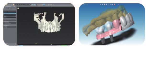
P R I N C I P E S       G É N É R A U X
L’ORGANISATION DU FLUX NUMÉRIQUE EN DENTISTERIE

La conception-fabrication assistée par ordinateur (CFAO) est donc le                CAD-CAM (computer-aided design/computer-aided
procédé qui permet, à l’aide d’un système automatisé, de concevoir et de            manufacturing) is thus the process which allows, using
                                                                                    an automated system, to plan and design the geometry
programmer la géométrie d’une pièce à usiner (CAO), et de réaliser les              of a workpiece (CAD), as well as to perform the various
différentes opérations d’usinage afin d’obtenir in fine une pièce conforme          machining operations in order to eventually obtain a
au dessin de départ (FAO).                                                          workpiece that is adequate with the initial drawing
                                                                                    (CAM).
L’intérêt de ces technologies dépasse évidemment le simple cadre de la              The interest of these technologies goes obviously
mécanique. Notre capacité, aujourd’hui, en science médicale, à importer             beyond the mechanics sector. Today, our ability in
                                                                                    medical sciences to import an existing clinical situation
une situation clinique existante pour la visualiser (à des fins diagnostiques       in order to visualize it (for diagnosis purposes for
par exemple), et bien entendu modéliser puis concevoir un traitement                example), and then to model and perform a prosthetic
prothétique donne de nouvelles perspectives à notre exercice.                       treatment offers new perspectives to our practice.
Et, fort heureusement, la dentisterie n’est pas en reste. Pour autant, cette        Very luckily, dentistry has not been left behind. However,
« dématérialisation » d’un certain nombre d’étapes ou de supports dans              this “dematerialization” of some stages or supports in
                                                                                    our practice arouses many questions about the use of
notre pratique suscite une multitude d’interrogations sur l’articulation de         these technologies in “dental art” such as we know it.
ces technologies avec l’« art dentaire » tel que nous le connaissons.

LA TECHNOLOGIE CFAO                                                                 THE CAD-CAM TECHNOLOGY
En 1973, François Duret propose d’appliquer le concept de la CFAO à la              In 1973, François Duret suggested applying the CAD-
dentisterie (Duret, 1974). Sa thèse sur l’empreinte optique a pavé le chemin        CAM concept to dentistry (Duret F, 1974). His thesis on
                                                                                    the optical impression has paved the way of the evolution
de l’évolution de la CFAO jusqu’à aujourd’hui. Et depuis une dizaine                of CAD-CAM until today. For a decade, the use of CBCT,
d’années, l’utilisation du CBCT, les empreintes et modèles digitaux, les            digital models and impressions, the reconstructions
reconstructions réalisées en CFAO, etc., se sont immiscés petit à petit dans        performed with CAD-CAM, etc. have progressively
le flux de travail de notre exercice. Tout l’intérêt (espéré) de ces technologies   integrated the working flow of our practice. The
réside dans le gain de précision, de prédictibilité et de temps.                    (expected) interest of these technologies lies in greater
                                                                                    accuracy, higher predictibility and time-saving.
À la différence de la CFAO appliquée dans d’autres disciplines, celle utilisée      Unlike the CAD-CAM used in other fields, the one used
en dentisterie ne crée pas un design 3D de toutes pièces. En effet, il s’agit       in dentistry does not create a complete 3D design.
d’abord de récupérer les données physiques du patient. Cette première               Indeed, the patient’s physical data must first be collected.
étape est donc une étape d’acquisition des données cliniques à l’aide d’un          This first stage consists in gathering the clinical data
arsenal de scannage, qui permettra de transformer ces données physiques             with several scanning tools, which will allow to transform
en données virtuelles, enregistrées au format STL (fichier ouvert) ou calquées      these physical data into virtual data, recorded in the STL
                                                                                    format (open file) or modeled on this format, although
sur ce format, mais dont l’accessibilité est restreinte (fichier fermé).            with a restricted accessibility (closed file).
Une fois les données cliniques importées dans l’ordinateur, les étapes              Once the clinical data have been imported into the
ultérieures suivent le schéma classique de la CFAO. Les données virtuelles          computer, the following stages are similar to the standard
sont intégrées dans le logiciel de CAO et permettent la modélisation de la          pattern of CAD-CAM. The virtual data are integrated into
pièce. La maquette modélisée est ensuite exportée vers un centre de                 the CAD software and allow the modeling of the part.
                                                                                    The digital mock-up is then exported to a manufacturing
production (FAO), dont la ou les machines sont directement contrôlées par           site (CAM) fitted with one or several machines that are
ordinateurs.                                                                        directly controlled by computers.

Le transfert des informations entre les différentes unités de la CFAO dépend        The information transfer between the various units of
du format avec lequel sont enregistrées ou transférées les données.                 CAD-CAM depends on the format with which the data
Aujourd’hui encore, deux systèmes cohabitent :                                      are recorded or transferred. Today, two systems still
                                                                                    coexist:
– les systèmes dits ouverts : le fichier émis après numérisation est un             –The so-called open systems: the file obtained after
fichier neutre et universel, codé au format STL. Ce format numérique peut           digitization is a neutral and universal file, coded in the
donc être lu par tous les systèmes numériques présents dans la chaîne               STL format. This digital format can thus be read by all
CFAO. La communication entre tous les outils de CAO et FAO est permise.             the existing digital systems in the CAD-CAM process
Le praticien est, par exemple, libre de choisir son centre de production,           chain. The communication between all the tools of CAD
                                                                                    and CAM is possible. For example, the practitioner is free
indépendamment de son logiciel de CAO et de la marque de la caméra                  to choose his production site, regardless of his CAD
optique utilisée ;                                                                  software, and the brand of the optical camera.

148 ROS – SEPTEMBRE/SEPTEMBER 2015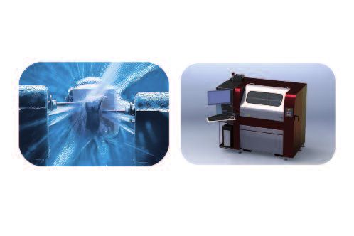
P R I N C I P E S        G É N É R A U X
L’ORGANISATION DU FLUX NUMÉRIQUE EN DENTISTERIE

– les systèmes dits fermés : le format numérique du fichier est propre au          –The so-called closed systems: the digital format of the
système de CAO utilisé et ne permet donc pas la communication avec                 file is specific to the CAD system and thus does not
                                                                                   allow any communication with other CAD softwares.
d’autres logiciels de CAO.                                                         Consequently, the operator can only use one CAD-CAM
Ainsi, l’opérateur est contraint à utiliser un seul et unique système de CFAO :    system: the connection between the scanner, CAD and
le lien entre scanner, CAO, et FAO n’est possible qu’avec les modules d’un         CAM can only be made with the modules of the same
même système. Les fichiers sont donc spécifiques à chaque système et ne            system. Files are thus specific to each system and
peuvent être lus par les autres.                                                   cannot be read by others.
Derrière une stratégie marketing indéniable, il y a aussi la volonté de            Beyond an undeniable marketing strategy, there is also
                                                                                   a will to control the quality of the entire digital process;
contrôler la qualité de toute la chaîne numérique, ce qui est plus facile à ga-    it is easier for the supplier to achieve this goal when the
rantir par le fournisseur lorsque le système est fermé, c’est-à-dire lorsqu’il     system is closed, i.e when he/she is the only one to
est le seul à gérer les fichiers numériques. Cependant, de plus en plus les        manage the digital files. However, more and more
sociétés tendent à ouvrir leurs fichiers au format STL.                            companies tend to open their files to the STL format.
D’un point de vue technologique, la chaîne numérique comprend donc trois           Technologically, the digital chain includes 3 stages that
                                                                                   follow one another, in that order (fig. 1):
étapes qui se succèdent, dans cet ordre (fig. 1) :                                 - Collection of the virtual data
– acquisition des données virtuelles ;                                             - CAD modeling
– modélisation sur logiciel CAO ;                                                  - Manufacturing or CAM
– fabrication ou FAO.

                                                                                   Fig. 1. Étapes de la chaîne CFAO.
                                                                                   Fig. 1. Stages in the CAD-CAM chain.

                       C          F         A         O                            Fig. 2. Étapes de la CFAO et articles correspondant.
                                                                                   Fig. 2. Stages of CAD-CAM and their corresponding article.
                                                                    ▲

         ACQUISITION             MODÉLISATION              FABRICATION
         COLLECTION              CAD MODELING             MANUFACTURING

  1

              ARTICLE 2                       ARTICLE 3                       ARTICLE 4                            ARTICLE 5

          Diagnostic Virtuel               Chirurgie guidée               Empreinte Optique                    Prothèse CFAO
          Virtual Diagnosis                Guided Surgery                 Optical impression                 CAD-CAM prosthesis
  2

D’un point de vue clinique et dans le cadre d’un traitement implantaire, par       Clinically, and within the framework of an implant
                                                                                   treatment for example, the sequence of steps is
exemple, l’enchaînement des étapes se fait de la manière suivante                  performed as follows (this refers to the articles
(correspondant aux articles de ce numéro spécial) (fig. 2) :                       published in this special issue) (fig. 2):

149 ROS – SEPTEMBRE/SEPTEMBER 2015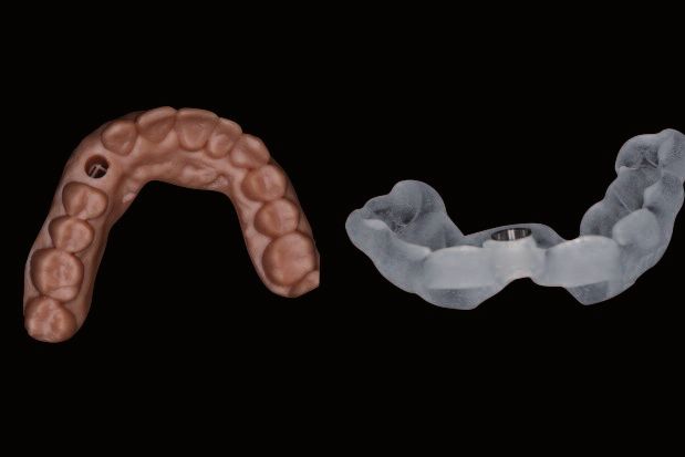
P R I N C I P E S              G É N É R A U X
L’ORGANISATION DU FLUX NUMÉRIQUE EN DENTISTERIE

– Diagnostic virtuel (article 2) : technique de prévisualisation du sourire        - Virtual Diagnosis (article 2) : Smile preview technique
dans la réhabilitation du secteur antérieur.                                       in the rehabilitation of the anterior sector.
                                                                                   - Guided Surgery (article 3) : The contribution of bone
– Chirurgie guidée (article 3) : l’apport de la chirurgie guidée par ordinateur    grafting in the treatment of severely resorbed crests.
dans le traitement des crêtes sévèrement résorbées.                                - Optical impression (article 4).
– Empreinte optique (article 4).                                                   - CAD-CAM prosthesis (Article 5) : Contribution of
– Prothèse CFAO (article 5) : l’apport du numérique dans la réhabilitation         digital technology in the rehabilitation of completely
de l’édenté complet.                                                               edentulous patients.
Le but de ce premier article est de présenter l’articulation du flux numérique     The purpose of this first article is to present the
d’un point de vue technologique, afin :                                            management of the digital stream from a technological
– de comprendre l’utilité et de faire un état des lieux des dispositifs            point of view in order to:
biomédicaux à notre disposition ;                                                  - Understand its usefulness and review the biomedical
– de présenter les différents acteurs industriels ;                                devices currently at our disposal.
                                                                                   - Present the various industrial actors.
– de comprendre la transmission des données « digitales » dans les                 - Understand the “digital” data transfer in the various
différentes étapes de la procédure ;                                               stages of the procedure.
– d’entrevoir les perspectives d’avenir.                                           - Take a glimpse at the future prospects.

1. ACQUISITION DES DONNÉES VIRTUELLES                                              1. VIRTUAL DATA ACQUISITION
                                                                                   The acquisition of virtual data is the first stage in the
L’acquisition des données virtuelles est la première étape dans la chaîne          digital chain. It is a major step since it allows to collect
numérique. C’est une étape majeure, puisqu’elle permet la récupération             the patient’s physical data to convert them in computer
des données physiques du patient pour les convertir en algorithme                  algorithm. It is the prerequired stage to initiate the CAD-
informatique. C’est l’étape prérequise pour initier le procédé de CFAO. C’est      CAM process. As a consequence, the rest of the digital
                                                                                   chain depends on it. During this stage, a maximum
donc d’elle que dépend le reste de la chaîne numérique. Il s’agit ici de           number of data concerning the clinical situation must
recueillir un maximum d’informations sur la situation clinique, que ce soit        be collected in order to help the planning, the
pour assister la planification, le positionnement de l’implant ou la réalisation   positioning of the implant and the manufacturing of the
de la restauration prothétique.                                                    prosthetic restoration.
Les moyens d’acquisition utilisés dépendent de la phase de traitement              The means of acquisition vary according to the phase of
                                                                                   treatment (diagnostic, surgical, or restorative) (fig. 3).
concernée (diagnostique, chirurgicale, ou restauratrice) (fig. 3).

               CONE BEAM CT                      SCANNER INTRA-ORAL    SCANNER EXTRA-ORAL                     SCANNER FACIAL
               CONE BEAM CT                      INTRAORAL SCANNER     EXTRAORAL SCANNER                      FACIAL SCANNER
   3

Fig. 3. Dispositifs d’acquisition des données.
Fig. 3. Devices for data acquisition.

En conséquence, le modèle physique à numériser peut donc être l’anatomie           Consequently, the physical model to be digitized may
osseuse, les arcades dentaires du patient, une arcade dentaire représentée         be the osseous anatomy, the patient’s dental arches, a
                                                                                   dental arch represented on a model, and even the
sur modèle, voire même le visage du patient.                                       patient’s face.
Ces dispositifs d’acquisition de données sont des scanners. En fonction du         The data acquisition devices are scanners. According to
modèle à scanner, ils peuvent être volumiques (CBCT) ou surfaciques, d’une         the model to be scanned, they can either be volume
part ; intra-oraux, de laboratoire ou faciaux, d’autre part. Les logiciels qui     (CBCT) or surface on one hand, intraoral, laboratory or
                                                                                   facial on the other hand. Nowadays, the software that
interpréteront ces fichiers en images 3D permettent aujourd’hui de faire           will interpret these files in 3D images allows to merge
converger des données issues des différents types de scanners.                     the data coming from these different types of scanners.

150 ROS – SEPTEMBRE/SEPTEMBER 2015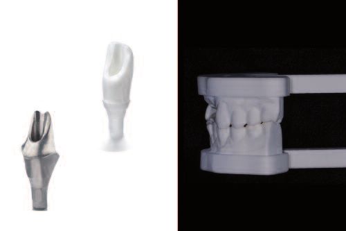
P R I N C I P E S       G É N É R A U X
L’ORGANISATION DU FLUX NUMÉRIQUE EN DENTISTERIE

CONE BEAM COMPUTED TOMOGRAPHY (CBCT)                                               CONE BEAM COMPUTED TOMOGRAPHY (CBCT)
Le CBCT intervient à la fois comme outil de diagnostic ou comme outil de           CBCT can be used both as a diagnostic tool and a tool
                                                                                   for therapeutic planning (computer-aided surgery for
planification thérapeutique (chirurgie assistée par ordinateur, par exemple).      example). This cone beam imaging technique allows to
Il procède de l’imagerie par faisceau conique et permet l’obtention de tout        visualize an entire volume in one single rotation. The
un volume en une seule rotation. L’image obtenue peut être reconstruite en         image can be reconstructed in a panoramic view, surface
panoramique, modèle surfacique ou 3D. La finesse de l’image est condition-         model or 3D. The image accuracy depends on the size of
née par la taille des voxels lors de l’acquisition. Le réglage des densités, ce-   voxels during the acquisition. However, the setting of
pendant, ne se fait que par modulation du contraste, ce qui rend                   densities can only be made with a modulation of
                                                                                   contrast, which makes the exploration of soft tissues
l’exploration des tissus mous difficile. Mais si la résolution en densité est      difficult. In spite of the rather poor density resolution,
médiocre, la résolution spatiale est comparable, voire meilleure, que celle        the spatial resolution is comparable, and even better,
obtenue avec la tomodensitométrie.                                                 than the one obtained with computed tomography.
Les avantages incontestables du CBCT par rapport au scanner conven-                The irrefutable advantages of CBCT compared to
tionnel sont :                                                                     conventional scanner are:
                                                                                   - Much lower radiation doses.
– des doses d’irradiation bien inférieures ;                                       - A lesser importance of metallic artefacts.
– la moindre importance des artefacts métalliques.                                 The digital information is collected in DICOM format
Les informations numériques obtenues sont au format Dicom (Digital Ima-            (Digital Imaging and Communication in Medicine). This
ging and Communication in Medicine). Ce format a été créé par les fabri-           format was created by the medical industry manufacturers
cants de l’industrie médicale afin de centraliser les données informatiques        to centralize the computing data stemming from 3D
                                                                                   imaging as well as the patient’s personal information
issues de l’imagerie 3D ainsi que les informations personnelles du patient         going with them (such as the patient’s name, his/her
qui les accompagnent (nom du patient, date de naissance, etc.).                    birthdate, etc.).

SCANNER INTRA-ORAL                                                                 INTRAORAL SCANNER
                                                                                   The first digital intraoral scanner designed for dentistry
Le premier scanner intraoral numérique conçu pour dentisterie a été                was introduced at the beginning of the 1980s by Dr Werner
introduit dans le début des années 1980 par le Dr Werner Mörmann, un               Mörmann, a Swiss dentist, and Marco Brandestini, an
dentiste suisse, et Marco Brandestini, un ingénieur électricien italien            Italian electrical engineer (Brandeslini M. et al., 1989).
(Brandeslini et coll., 1989).                                                      Intraoral scanners work like a camera, with the exception
Les scanners intra-oraux fonctionnent de façon similaire à une caméra, à           that they have a sophisticated technology featuring an
l’exception près qu’ils disposent d’une technologie sophistiquée avec un           optical sensor which measures the reflection of light in
                                                                                   all the directions of space, recording the tridimensional
capteur optique qui mesure la réflexion de la lumière dans toutes les              positioning of the object.
directions de l’espace, enregistrant le positionnement de l’objet de façon         This three-dimensional representation on the software
tridimensionnelle.                                                                 can be achieved thanks to a process of alignment
Cette représentation tridimensionnelle sur le logiciel est permise grâce à un      dictated by a computer algorithm. This step consists in
processus d’alignement dicté par un algorithme informatique. Cette étape           recording a multitude of points on the three-dimensional
                                                                                   surfaces of the model. This is what we call digitization.
consiste à relever une multitude de points sur les surfaces tridimension-          These clouds of virtual points are then connected to
nelles du modèle. On parle de digitalisation. Ces nuages de points virtuels        each other. This process results in a mesh which
sont ensuite reliés entre eux. Ce procédé permet l’obtention d’un maillage         constitutes the 3D model, the virtual replica of the
qui constitue le modèle 3D, réplique virtuelle du modèle physique. Le modèle       physical model. The model can be seen immediately on
est immédiatement visualisable sur le moniteur du praticien sur lequel est         the practitioner’s monitor to which the optical sensor is
                                                                                   connected, and can be exported, in the STL format, into
connecté le capteur optique, et peut être exporté, sous le format STL, dans        the CAD software to model a prosthetic element, an
le logiciel de CAO pour modéliser un élément prothétique, une gouttière            orthodontic splint, a surgical guide, a segmented model,
orthodontique, un guide chirurgical, un modèle segmenté, etc.                      etc.
Une quinzaine de scanners intra-oraux permettent aujourd’hui la prise              Today, about fifteen intraoral scanners allow to take
d’empreinte intra-orale au cabinet dentaire (Joda et coll., 2014) (fig. 4 et       intraoral impressions in the dental office (Joda T. et al.,
tableau 1). La capture se fait à l’aide d’un dispositif de type caméra             2014) (fig. 4) (table 1). The capture is performed with a
                                                                                   portable camera that is included in a monitor or is
portative qui appartient à un moniteur ou bien se connecte directement à           directly connected to a computer with a USB port or
un ordinateur par un port USB ou FireWire. Selon les fabricants, les données       FireWire. Depending on the manufacturers, the collected
recueillies peuvent être traitées directement sur un logiciel intégré et           data can be directly processed with an integrated
utilisées au cabinet ou bien externalisées vers un centre qui dispose d’un         software and used in the dental office or outsourced
logiciel de modélisation adapté.                                                   towards a center fitted with an adapted modeling
                                                                                   software.

151 ROS – SEPTEMBRE/SEPTEMBER 2015
P R I N C I P E S G É N É R A U X
L’ORGANISATION DU FLUX NUMÉRIQUE EN DENTISTERIE
Fig. 4. Principaux dispositifs d’empreinte optique disponibles
sur le marché.
Fig. 4. Main optical impression systems available on the market.
ITERO, CADENT TRIOS, SHAPE LAVA, 3M
OMNICAM, CEREC PLANSCAN, PLANMECA GC AADAV, GC
4
Tableau 1. CARACTÉRISTIQUES DES PRINCIPAUX DISPOSITIFS D’EMPREINTE OPTIQUE ACTUELLEMENT DISPONIBLES SUR LE MARCHÉ
Table 1. SPECIFICITIES OF THE MAIN OPTICAL IMPRESSION DEVICES CURRENTLY AVAILABLE ON THE MARKET
EMPREINTE
OPTIQUE CEREC 3SHAPE CADENT 3M ESPE PLANMECA CARESTREAM GC
OPTICAL
IMPRESSION
Dernier produit, SCANNER
année de OMNICAM, TRIOS 3, ITERO TRUE PLANSCAN, INTRA-ORAL CS AADVA IOS,
lancement 2012 2015 ELEMENT, DEFINITION, 2014 3500, 2015
Latest item, 2015 2014
launch year 2014
Année de
lancement
(1er modèle) 1985 2011 2009 2007 2014 2014 2015
launch year
(First model)
Nbre de modèles
commercialisés 5 3 2 3 1 1 1
Number of
marketed models
Source LED BLANCHE LASER LASER ROUGE LED BLEUE LASER BLEU LED LED BLEUE
de lumière WHITE LED LASER RED LASER BLUE LED BLUE LASER LED BLUE LED
Light source
Profondeur de 0 à 13,5 mm de 0 à 13,5 mm de 0 à 13,5 mm de 0 à 15 mm de 5 à 15 mm N/A de 0 à 15 mm
de champ 0 to 13.5 mm 0 to 13.5 mm 0 to 13.5 mm 0 to 15 mm 5 to 15 mm NA 0 to 15 mm
Field Depth
Type de capture VIDÉO VIDÉO PHOTO VIDÉO VIDEO PHOTO VIDÉO
Type of capture
OUI : associable OUI : associable
avec usinage de avec usinage de
Usinage In-office OUI marque tiers marque tiers NON OUI : Planmill OUI NON
In-office milling YES YES: compatible YES: compatible NO YES: Planmill YES NO
with another with another
milling brand milling brand
Import/Export OUI : (license OUI : (license
de fichiers STL requise) requise) OUI OUI OUI OUI OUI
ouvert YES: (required YES: (required YES YES YES YES YES
Import/Export of license) license)
STL file (open)
152 ROS – SEPTEMBRE/SEPTEMBER 2015P R I N C I P E S G É N É R A U X
L’ORGANISATION DU FLUX NUMÉRIQUE EN DENTISTERIE
EMPREINTE
OPTIQUE CEREC 3SHAPE CADENT 3M ESPE PLANMECA CARESTREAM GC
OPTICAL
IMPRESSION
CFAO intégrée OUI OUI NON NON OUI OUI NON
Integrated YES YES NO NO YES YES NO
CAD-CAM
Poudrage NON NON NON OUI NON NON NON
Powdering NO NO NO YES NO NO NO
Entre 45 000 Entre 35 000
Cout unitaire et 55 000 € et 45 000 €
(dernier modèle) (supp. pour Entre 45 000 Entre 25 000 Entre 15 000 (supp. pour Entre 25 000 N/A
Unit cost usineuse) et 55 000 € et 35 000 € et 25 000 € usineuse) et 35 000 € NA
(Last model) 45-55 000€ 35-45 000€ 25-35 000€ 15-25 000€ 35-45 000€ 25-35 000€
(extra fee for (extra fee for
milling machine) milling machine)
Frais scannage GRATUIT GRATUIT PAYANT GRATUIT GRATUIT GRATUIT N/A
Scanning cost FREE FREE CHARGE FREE FREE FREE NA
Acq. Couleur OUI OUI NON OUI NON OUI NON
Color Acq. YES YES NO YES NO YES NO
Prise de teinte NON OUI NON NON NON NON NON
Shade Taking NO YES NO NO NO NO NO
Unité (moniteur Unité centrale Unité centrale Unité centrale
central, kart, port Unité
sur
centrale
caisson à Port USB sur caisson à sur caisson à Port FireWire ou
Unité centrale
sur caisson à
USB…) roulettes Installation roulettes roulettes Thunderbolt Port USB roulettes
Central Central monitor fauteuil Central monitor Central monitor FireWire Port or USB port Central monitor
Processing Unit on mobile Central monitor on mobile on mobile Thunderbolt on mobile
(central monitor, pedestal USB port pedestal pedestal pedestal
Kart, USB port…) Armchair setting
Dans le marché dentaire, il existe aujourd’hui principalement trois types de On the dental market, there are nowadays three main
types of optical capture technologies (Lee S.I et al., 2012):
technologies de capture optique disponibles (Lee et coll., 2012) : - Triangulation
– la triangulation ; - Parallel confocal scanning
– le balayage parallèle confocal ; - Active wavefront sampling
– l’Active Wavefront Sampling (AWS).
The optical impression allows to achieve three different
goals:
L’empreinte optique permet d’atteindre trois objectifs distincts : 1. Collecting fully digital data used for the 3D diagnosis,
1. Acquérir des données entièrement numériques, destinées au diagnostic the surgical planning (in association with Cone Beam),
3D, à la planification chirurgicale (en association avec le Cone Beam) et à la and for the communication with the patient and the
communication avec le patient et l’équipe pluridisciplinaire. Ici, le processus multidisciplinary team. Here, the process of digital
de fabrication numérique est restreint à la phase visualisation et manufacturing is limited to the phase of visualization
and 3D modeling (CAD). No manufacturing is associated
modélisation 3D (CAO). Aucune fabrication n’y est associée. with it.
2. Fabriquer un élément prothétique directement à partir de la modélisation 2. Making a prosthetic element directly from the 3D
3D sans pour autant fabriquer de modèle physique. On parle ici de CFAO modeling with no need to make a physical model. Here,
directe. La conception et la fabrication de la pièce prothétique peuvent we speak of direct CAD-CAM. The design and
être réalisées dans un centre de production externalisé ou bien manufacturing of the prosthetic part can be handled in
an outsourced production site or immediately made in
immédiatement usinée au sein du cabinet par une fraiseuse « in-office » the dental office with an in-office milling unit provided
proposée par certains fabricants (Cerec, Planmeca, Lyra). by several manufacturers (Cerec, Planmeca, Lyra).
3. Acquérir un modèle virtuel pour en produire un modèle physique par le 3. Obtaining a virtual model in order to produce a
biais d’une imprimante 3D. Dans cette situation, le flux numérique n’est physical model with a 3D printer. In this case, the digital
utilisé qu’au stade de l’empreinte, et n’est donc que partiel. On parle ici de stream is only used at the stage of the impression, and
thus remains partial. We speak of semi-direct CAD-CAM.
CFAO semi-directe. Elle permet donc la conception numérique de pièces It allows the digital design of prosthetic parts such as
prothétiques, comme les armatures, mais autorise le travail du céramiste, frameworks for example, but also allows the work of the
encore irremplaçable lorsque, par exemple, l’esthétique est d’importance. lab technicianwho cannot be replaced when, for
example, aesthetics is most important.
153 ROS – SEPTEMBRE/SEPTEMBER 2015P R I N C I P E S G É N É R A U X
L’ORGANISATION DU FLUX NUMÉRIQUE EN DENTISTERIE
SCANNER EXTRA-ORAL OU SCANNER DE LABORATOIRE EXTRAORAL SCANNER OR LABORATORY SCANNER
La méthode traditionnelle pour emprunter le chemin de la CFAO consiste à The traditional method to use CAD-CAM consists in
scanning the models when they arrive at the laboratory,
scanner les modèles quand ils arrivent au laboratoire ou à numériser les or to digitize wax ups (abutments, frameworks). The data
wax-up (piliers, armatures). L’acquisition des données ne se fait plus direc- acquisition is not made directly on the patient any more, but
tement sur le patient, mais de façon indirecte via une pièce de transfert qui indirectly via a transfer tool, which may be an impression,
peut être une empreinte, un modèle en plâtre, un wax-up… On parle donc de a plaster cast, a wax up... This is what we call the indirect
technique de CFAO indirecte. Ici, la chaîne numérique est utilisée seulement CAD-CAM technique. Here, the digital chain is only used
in the laboratory and does not affect the practitioner’s
au laboratoire et n’affecte pas les habitudes de travail du praticien. C’est la working habits. This is currently the most widespread
technique de CFAO la plus employée à ce jour. Si la précision de ces scan- CAD-CAM technique. If the accuracy of these scanners
ners est reconnue, la numérisation porte avec elle l’accumulation des im- cannot be questioned, the digitization encompasses the
précisions liées aux déformations d’une prise d’empreinte et d’une coulée accumulation of inaccuracies due to deformations when
du plâtre conventionnelle, imprécisions qui ne sont pas présentes lorsque le the impression is taken and to a conventional plaster
cast - such inaccuracies do not exist when scanning is
scannage se fait directement en bouche (Logozzo et coll., 2008). directly made in mouth (Logozzo S. et al., 2008).
FACIAL SCANNER
SCANNER FACIAL This type of scanner works with a technology of
Ce type de scanner fonctionne par une technologie de lumière structurée. structured light. Like the laboratory scanner and the
À l’instar du scanner de laboratoire et du scanner intraoral, il enregistre la intraoral scanner, it records the surface of the targeted
object, in this case the patient’s face. Its use is most
surface de l’objet visé, en l’occurrence le visage du patient. Son utilisation interesting when the facial surface can be combined
trouve tout son intérêt lorsque la surface faciale peut être combinée avec with the surface obtained with the CBCT and the
celle obtenue avec le CBCT et le scanner intra-oral. Les informations intraoral scanner. The information about bone structures,
relatives aux structures osseuses, arcades dentaires et tissus mous sont dental arches and soft tissues can merge and create a
alors associées et créent un « avatar » virtuel de notre patient. En ce sens, virtual “avatar” of our patient. In this regard, this is
nowadays the closest element to the design of a virtual
il est l’élément qui nous rapproche aujourd’hui de la conception d’un patient patient. Besides of being a great tool of communication,
virtuel. En plus d’être un formidable élément de communication, il permet it also allows to simulate the planning of the treatment
de simuler la planification du traitement (Papaspyridakos et coll., 2015). (Papaspyridakos P et al., 2015).
2. LOGICIEL DE CAO : MODÉLISATION 2. CAD SOFTWARE: MODELING
Modeling can be performed in surgical purposes, for
La modélisation peut se faire à des fins chirurgicales, comme avant une example before a guided surgery, or in a prosthetic
chirurgie guidée, ou dans un but prothétique, dans le cadre de la conception purpose, for instance to handle the design of an implant
d’un pilier implantaire, par exemple (fig. 5). abutment (fig. 5).
Fig. 5. Principaux dispositifs de modélisation disponibles sur le
marché.
Fig. 5. Main modeling systems available on the market.
Fig. 6. Principaux logiciels de planification chirurgicale disponibles
sur le marché.
Fig. 6. Main surgical planning softwares available on the market.
LOGICIEL DE PLANIFICATION CHIRURGICALE LOGICIEL DE MODÉLISATION PROTHÉTIQUE
SURGICAL PLANNING SOFTWARE PROSTHETIC MODELING SOFTWARE
5
coDiagnostiX 9, Dental Wings Simplant, Materialise Nobel Guide, Nobel Galileos, Sirona
6
154 ROS – SEPTEMBRE/SEPTEMBER 2015P R I N C I P E S G É N É R A U X
L’ORGANISATION DU FLUX NUMÉRIQUE EN DENTISTERIE
Dans le premier cas, ce sont avant tout des logiciels de diagnostic In the first case, we mostly find diagnostic pre-implant
préimplantaire capable de lire les fichiers spécifiques l’imagerie 3D médicale softwares able to read the specific files of the medical
3D imaging (DICOM) (fig. 6). With the exception that
(Dicom) (fig. 6), à l’exception près qu’ils contiennent, pour la plupart, des most of them include advanced tools of virtual surgical
outils avancés de planification chirurgicale virtuelle (bibliothèque d’implant, planning (implant library, segmentation of the anatomical
segmentation des structures anatomiques, importation de projets structures, import of prosthetic projects) and the
prothétiques…) et la possibilité, in fine, d’y adjoindre un design de guide possibility, in fine, to add a surgical guide design that
chirurgical qui sera fabriquée par une imprimante 3D. Ceux communément will be made by a 3D printer. The softwares commonly
disponibles sur le marché aujourd’hui sont présentés dans le tableau ci- found on the market today are presented in the board
below. (table 2)
dessous (tableau 2).
Tableau 2. CARACTÉRISTIQUES DES PRINCIPAUX LOGICIELS DE PLANIFICATION CHIRURGICALE ACTUELLEMENT DISPONIBLES SUR LE MARCHÉ
Table 2. SPECIFICITIES OF THE MAIN SOFTWARES OF SURGICAL PLANNING CURRENTLY AVAILABLE ON THE MARKET
CAO - LOGICIEL DE
PLANIFICATION DENTAL WINGS PLANMECA NOBEL BIOCARE 3SHAPE
CAD PLANNING
SOFTWARE
Nom du logiciel CODIAGNOSTIX ROMEXIS NOBELCLINICIAN/NOBELGUIDE IMPLANT STUDIO
Software name
Reconstruction 3D OUI OUI OUI OUI
3D reconstruction YES YES YES YES
Bibliothèque implants OUI OUI OUI OUI
à disposition YES YES YES YES
Available implant library
(Nbre de fabricants
implantaires) NB > 30 NB > 30 Implant Nobel NB > 10
Number of implant
manufacturers
Import/Export de
fichiers STL ouvert OUI OUI NON OUI
Import/export of open STL YES YES NO YES
files
OUI : (modèle platre scanné par
Superposition modèle STL OUI OUI NobelProcera 2G) OUI
Superposition STL model YES YES YES: (plaster model scanned by YES
NobelProcera 2G)
Wax-up virtuel OUI OUI N/A OUI
Virtual wax-up YES YES NA YES
Passerelle directe avec une
plateforme prothétique OUI (DWOS) OUI (PlanCAD) OUI (NobelProcera 2G) OUI (Dental System)
Direct gateway with YES (DWOS) YES (PlanCAD) YES (NobelProcera 2G) YES (Dental System)
prosthetic platform
Conception/Fabrication de NON (en cours de
guide (chirurgie guidée) OUI développement) OUI OUI
Design/Guide manufacturing YES NO (under development) YES YES
(guided surgery)
Téléchargement des cas sur
logiciel en ligne NON NON NON OUI
Cases download on on-line NO NO NO YES
software
Prix d’acquisition du logiciel N/A N/A
(fourchette) 5 000 € 5 000 € NA NA
Price of software (range)
Système d’exploitation PC MAC ET PC PC PC
Operating system
155 ROS – SEPTEMBRE/SEPTEMBER 2015P R I N C I P E S G É N É R A U X
L’ORGANISATION DU FLUX NUMÉRIQUE EN DENTISTERIE
Ces logiciels ont donc la capacité de faire converger les données Dicom These softwares are thus able to merge DICOM data
(CBCT) avec les fichiers STL (scanner de surface des arcades du patient). (CBCT) with STL files (surface scanner of the patient’s
arches).
L’intérêt majeur de cette superposition est de visualiser les contours The major interest of this superposition is to visualize
gingivaux et prothétiques, tout en s’affranchissant de la réalisation d’un the gingival and prosthetic outlines, while eliminating
guide radiographique conventionnel réalisé au laboratoire (souvent trop the necessity to make a conventional radiographic
approximatif). Le deuxième intérêt est de créer un modèle 3D puis de guide manufactured in the laboratory (often too
produire un guide chirurgical adapté à la surface des dents ou des approximate). The second interest is to create a 3D
muqueuses en accord avec le positionnement tridimensionnel des implants. model before making a surgical guide adapted to the
surface of teeth or mucous membranes according with
Il s’agit là d’une chirurgie assistée par ordinateur (fig. 7). the three-dimensional positioning of implants. This is
called computer-aided surgery (fig. 7).
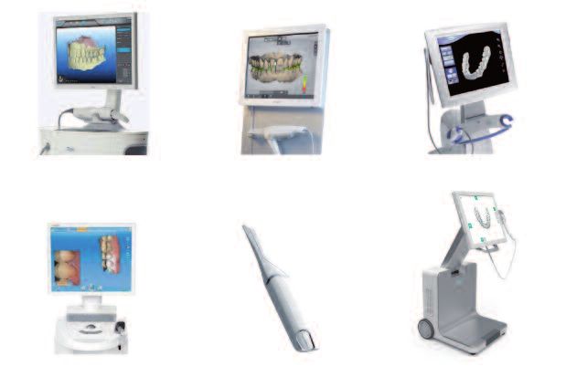
Fig. 7. Pièces fabriquées par technique additive ou impression
3D. Modèle de travail imprimé (à gauche) et guide chirurgical (à
droite).
Fig. 7. Parts manufactured with the additive technique or 3D
printing. Printed work model (on the left) and surgical guide (on
the right).
7
En plus d’apporter une assistance à l’acte chirurgical, ces logiciels Besides assisting the surgical act, these softwares often
have a similar platform dedicated for example to the
disposent souvent d’une plateforme similaire dédiée à la conception virtual design of models, or the design of the future
virtuelle de modèles, ou celle de la future armature prothétique par exemple prosthetic framework (Ex: Romexis, Dental Wings, Cerec,
(ex. : Romexis, Dental Wings, Cerec, 3Shape…) (fig. 8 et tableau 3). 3Shape ...) (fig. 8) (table 3).
Dental Wings 3Shape Dental CAD Cerec, Sirona
8
Fig. 8. Principaux logiciels de conception prothétique disponibles sur le marché.
Fig. 8. Main softwares of prosthetic design available on the market.
156 ROS – SEPTEMBRE/SEPTEMBER 2015P R I N C I P E S G É N É R A U X
L’ORGANISATION DU FLUX NUMÉRIQUE EN DENTISTERIE
Tableau 3. CARACTÉRISTIQUES DES PRINCIPAUX LOGICIELS DE PLANIFICATION PROTHÉTIQUE ACTUELLEMENT DISPONIBLES SUR LE MARCHÉ
Table 3. SPECIFICITIES OF THE MAIN SOFTWARES OF PROSTHETIC PLANNING CURRENTLY AVAILABLE ON THE MARKET
CAO - PLATEFORME
PROTHÉTIQUE NOBEL BIOCARE PLANMECA DENTAL WINGS 3SHAPE
CAD - PROSTHETIC
PLATFORM
Nom du logiciel NOBELPROCERA PLANCAD EASY DWOS DENTALSYSTEM
Software name
Plateforme ouverte NON (fichier STL fermé,
(Import/Export de fichiers intègre les systèmes d’implants
premium dans le catalogue
STL ouvert) produits) OUI OUI OUI
Open platform NO (closed STL file Integrates YES YES YES
(import/export of open STL the premium implant systems in
files) the product catalog)
NON
Smart fusion avec le OUI OUI
Intégré avec caméra optique scanner NobelProcera 2G PLANSCAN PLANMECA/3M Sortie caméra fin 2015 3Shape Trios
Integrated optical camera NO (Smart Fusion with YES Camera scheduled end 2015 YES
NobelProcera 2G scanner PLANSCAN PLANMECA/3M 3 Shape Trios
Intégré avec logiciel de
planification chirurgicale NOBELCLINICIAN ROMEXIS ET SIMPLANT CODIAGNOSTIX 3SHAPE IMPLANT STUDIO
Integrated software
of surgical planning
Prothèse implanto-portée OUI (NOBELPROCERA) OUI OUI OUI
Implant-borne prosthesis YES (NOBELPROCERA) YES YES YES
Prothèse conventionnelle OUI OUI OUI OUI
Conventional prosthesis YES YES YES YES
Prothèse adjointe NON NON OUI OUI
Removable prosthesis NO NO YES YES
Articulateur virtuel NON NON OUI OUI
Virtual Articulator NO NO YES YES
Système d’exploitation MAC ET PC PC SOUS WINDOWS 8 PC PC
Operating system PC WINDOWS 8
Sur le modèle numérique virtuel, l’opérateur va élaborer la future prothèse On the virtual digital model, the operator is going to
make the future prosthesis from a preform taken in an
à partir d’une préforme extraite d’une bibliothèque virtuelle. L’ensemble electronic library. All the characteristics of the piece to
des caractéristiques de la pièce à concevoir (épaisseur, limites, etc.) est be designed (thickness, margins, etc.) is are decided by
décidé par l’opérateur. La liste des applications est de plus en plus the operator. The list of the applications is more and
exhaustive, certains fabricants permettent la fabrication d’éléments more exhaustive, some manufacturers allow the
prothétiques sur dent naturelle (inlay-core, armature, couronne pleine) et manufacturing of prosthetic elements on natural teeth
sur implant (pilier, armature transvissée…), prothèse adjointe (base métal (inlay core, framework, full crown) and on implant
(abutment, screwed-retained framework ...), overdentures
stellite) ou des dispositifs orthodontiques. L’intérêt de la conception (metal base Stellite) or orthodontic devices. Computer-
assistée par ordinateur reste le gain de temps et de précision, pouvant être aided design remains interesting because it’s
inférieur à 50 µm. De cette précision découlent les ajustements parfaits time-saving and provides outstanding accuracy, since it
des pièces et la possibilité de concevoir des pièces dans des matériaux may be lower than 50 µm. This accuracy results in
uniquement usinables, comme la zircone. Une fois la prothèse ou le guide perfect adjustments of parts and the possibility to
design parts in machinable materials only, such as
chirurgical élaborés virtuellement, il reste à le produire physiquement, dans zircone for example.
le matériau choisi pour sa fabrication (fig. 9). Once the prosthesis or the surgical guide have been
virtually designed, it must be physically manufactured in
the adequate material (fig. 9).
157 ROS – SEPTEMBRE/SEPTEMBER 2015P R I N C I P E S G É N É R A U X
L’ORGANISATION DU FLUX NUMÉRIQUE EN DENTISTERIE
USINEUSE IMPRIMAMTE 3D
MILLING MACHINE 3D PRINTER
9 10
Fig. 9. Pièces fabriquées par technique soustractive ou usinage. Pilier implantaire Fig. 10. Procédés de fabrication par soustraction (usineuse) et par addition
par CFAO et modèle de travail usiné. (imprimante 3D).
Fig. 9. Parts manufactured with the subtractive technique or milling. CAD-CAM Fig. 10. manufacturing processes by subtraction (milling machine) and by addition
implant abutment and machined work model. (3D printer).
3. TECHNOLOGIES DE FAO : FABRICATION 3. CAM TECHNOLOGIES: MANUFACTURING
The role of CAM is to write the program, which allows
Le rôle de la FAO est d’écrire le programme qui permettra le fonctionnement the functioning of the computer numerical control (CNC)
des machines-outils à commande numérique (MOCN) pour fabriquer la pièce machine tools in order to manufacture the part designed
conçue par la CAO. Le logiciel génère le programme ISO qui permet son by CAM. The software generates the ISO program, which
exécution par la machine-outil. allows its fabrication by the machine tool.
Il existe deux systèmes de fabrication numérique aujourd’hui (fig. 10) : There are currently two systems of numerical
manufacturing (fig. 10):
– les procédés soustractifs ; • The subtractive process
– les procédés additifs par strates. • The additive process with sintering
Le procédé soustractif est le procédé traditionnel de FAO. Il s’agit d’usiner – The subtractive process is the traditional CAM process.
dans un bloc de matière la pièce à fabriquer, à l’aide de machines-outils It consists in manufacturing the piece in a block of
commandées par le logiciel CAO. La pièce est donc mise en forme par material with machine tools controlled by the CAD
software. The piece is shaped by subtraction of material.
soustraction de matière. La capacité des machines-outils à fraiser des The capacity of machine tools to mill complex parts
pièces complexes augmente avec le nombre d’axes de déplacement des increases with the number of axes of travel of the mills.
fraises. Ces machines peuvent usiner toutes sortes de matériaux, comme These machines can work on all sorts of materials such
du titane, du chrome-cobalt, de la zircone frittée ou préfrittée, ou des as titanium, cobalt-chromium, pre-sintered or sintered
matériaux résines calcinables. zirconia, or burn-out resin materials.
The interest of the machining lies in:
L’intérêt de l’usinage réside dans : - the high accuracy of milling (irrefutable asset in the
– l’excellente précision du fraisage (avantage indéniable dans les recons- prosthetic reconstructions requiring great passivity)
tructions prothétiques qui nécessitent une grande passivité) ; - The flexibility of materials that can be used
– la flexibilité des matériaux utilisables ; - The homogeneity in the densities of materials
– l’homogénéité des densités des matériaux ; - The resistance of machined parts in time
– la résistance des pièces usinées dans le temps. However, machining generates a considerable material
loss; it is thus material consuming. Besides, the
En revanche, l’usinage s’accompagne de perte de matière importante, il est reproduction of details depends on the diameter of the
donc peu économe en matériaux. Par ailleurs, la reproduction des détails est mill and its wear must regularly be checked. The
tributaire du diamètre de la fraise dont l’usure doit être régulièrement vé- complexity of the parts to manufacture also implies a
rifiée. La complexité des pièces à produire implique également un nombre sufficient number of axes of travel of the mills. Finally,
suffisant d’axes de déplacement des fraises. Enfin, les pièces sont néces- the parts must be fabricated successively, at the rate
of one part made by one machine tool, which limits the
sairement produites successivement, soit à raison d’une pièce produite par productivity.
machine-outil, ce qui limite la productivité.
158 ROS – SEPTEMBRE/SEPTEMBER 2015P R I N C I P E S G É N É R A U X
L’ORGANISATION DU FLUX NUMÉRIQUE EN DENTISTERIE
Les procédés additifs, communément appelés impression 3D, sont des -The additive processes, commonly called 3D printing,
processus de fabrication directe. La pièce est entièrement fabriquée par are direct manufacturing methods. The part is entirely
manufactured by laying down successive layers of
apposition de couches successives de matière. Il n’y a donc pas de bloc de material. There is no milling block and no cast: the
fraisage ni de moule : l’économie de matière est réelle. Mais l’avantage economy of material is real. But the main advantage lies
principal réside surtout dans la capacité de ces techniques additives à in the capacity of these additive techniques to make
réaliser des pièces prothétiques dont l’anatomie est complexe ou impos- prosthetic parts with complex anatomies, or parts that
sible à obtenir par usinage ou par coulée classique (Thiel et coll., 2008). cannot be made with the machining process or the
Il existe aujourd’hui trois types de techniques additives : traditional casting process (Thiel F et al., 2008).
There are three types of additive techniques today:
– la stéréolithographie ; · Stereolithography
– l’impression 3D multijet (tableau 4) ; · Multi-Jet 3D printing (table 4)
– le frittage par laser ou microfusion. · Laser or microfusion sintering
Tableau 4. CARACTÉRISTIQUES DES PRINCIPALES IMPRIMANTES 3D ACTUELLEMENT DISPONIBLES SUR LE MARCHÉ
Table 4. SPECIFICITIES OF THE MAIN 3D PRINTERS CURRENTLY AVAILABLE ON THE MARKET
IMPRIMANTE 3D PRODWAYS 3D SYSTEM STRATASYS ENVISIONTECH
3D PRINTER
Nom modèle (le plus adapté) PERFECTORY MICRO
Model name (most adequate) L500D PROJET3500 OBJET30
ORTHO3D PRINTER
Technologie utilisée MOVING LIGHT - SCANDLP MULTIJET MULTIJET FIXE DLP
Technology
Résolution 32 MICRONS 66 MICRONS 45 MICRONS 98 MICRONS
Resolution
Épaisseur des couches 25 À 150 MICRONS 33 MICRONS 28 MICRONS 50 À 100 MICRONS
Layer thickness 25 TO 150 MICRONS 50 TO 100 MICRONS
Précision 75 % DANS 50 MICRONS 25 % DANS 50 MICRONS 25 % DANS 50 MICRONS 40 % DANS 50 MICRONS
Accuracy 75% IN 50 MICRONS 25% IN 50 MICRONS 25% IN 50 MICRONS 40% IN 50 MICRONS
Vitesse d’exécution TBD : 400 x 300 mm en 30” 300 x 185 mm en 45” 300 x 200 mm en 60” 100 x 75 mm en 40”
(base de 10 modèles) TBD: 400 x 300 mm in 30s 300 x 185 mm in 45s 300 x 200 mm in 60sec 100 x 75 mm in 40s
Execution speed (10 models)
Matériaux biocompatibles OUI NON OUI OUI
Biocompatible materials YES NO YES YES
Modèle OUI OUI OUI OUI
FABRICATION – MANUFACTURING
Model YES YES YES YES
Modèle + gencive OUI NON NON NON
flexible YES NO NO NO
Model + Flexible gums
Guides chirurgicaux OUI NON OUI OUI
Surgical guide YES NO YES YES
Gouttière ortho OUI NON N/A N/A
Ortho splint YES NO NA NA
Provisoire OUI NON NON NON
Provisional YES NO NO NO
Pays FRANCE ÉTATS-UNIS ÉTATS-UNIS ALLEMAGNE
Country GERMANY
Fourchette de prix 210 K€ 130 K€ 80 K€ N/A
Price range NA
Distributeur pour la France BIOTECH, DREVE (Allemagne) Laboratoire de proximité Laboratoire de proximité Laboratoire de proximité
Dealer in France BIOTECH, DREVE (Germany) Local laboratory Local laboratory Local laboratory
159 ROS – SEPTEMBRE/SEPTEMBER 2015Vous pouvez aussi lire