VSE EF ECOFLOW DÉBITMÈTRES ALUMINIUM POUR MONTAGE EN LIGNE ALUMINIUM IN-LINE FLOW METER - Sepem permanent

La page est créée Veronique Alexandre
 
CONTINUER À LIRE
VSE EF ECOFLOW DÉBITMÈTRES ALUMINIUM POUR MONTAGE EN LIGNE ALUMINIUM IN-LINE FLOW METER - Sepem permanent
Solutions for Fluid Technology

  VSE EF ECOFLOW
  DÉBITMÈTRES ALUMINIUM POUR MONTAGE EN LIGNE
  ALUMINIUM IN-LINE FLOW METER
VSE EF ECOFLOW DÉBITMÈTRES ALUMINIUM POUR MONTAGE EN LIGNE ALUMINIUM IN-LINE FLOW METER - Sepem permanent
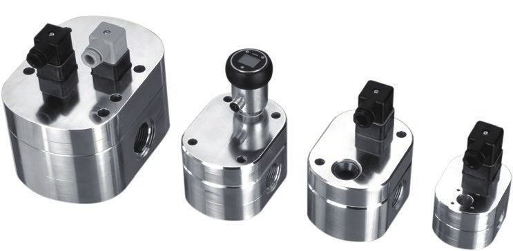
2   DÉBITMÈTRES VOLUMÉTRIQUES                                           ALUMINIUM FLOW METER
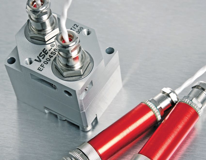
    ALUMINIUM SÉRIE VSE EF ECOFLOW                                      VSE EF ECOFLOW SERIES

    Fonctionnant suivant le même principe que les débit-                Based on the same meshing gear principle as the VSE
    mètres VSE des séries VSI et VHM, les débitmètres VSE               series VSI and VHM, the VSE EF ecoflow sensor measu-
    EF ecoflow mesurent les débits de fluides visqueux, et              res viscous media, however as in-line-device.
    sont directement insérés en ligne, sans embase.
                                                                        An integrated, magnetoresistive pick-up with PNP or
    Un détecteur magnéto-résistif intégré, à commutation                NPN-switching output produces one impulse per tooth
    PNP ou NPN, délivre une impulsion par dent détectée,                with a value of :
    d‘une valeur

      Volume / Impulsion                       Taille                     Volume / Impulse                            Size
              0.04 cm   3
                                             EF 0.04                               0.04 cm   3
                                                                                                                      EF 0.04
                0.1 cm3                      EF 0.1                                 0.1 cm3                           EF 0.1
                0.4 cm  3
                                             EF 0.4                                 0.4 cm   3
                                                                                                                      EF 0.4
                  2 cm  3
                                             EF 2                                      2 cm  3
                                                                                                                      EF 2
                  4 cm  3
                                             EF 4                                      4 cm3                          EF 4

    Option:                                                             Optional:
    Afficheur LCD de débit avec sortie analogique et deux               LCD flow display with analogue output and two limit
    seuils limites, intégré sur le débitmètre.                          values, mounted on the flow meter.

    La fréquence des impulsions est proportionnelle à la                The impulse frequency is proportional to the revolu-
    vitesse de rotation des roues dentées, qui sont mises en            tions of the gear wheels, which are driven by the volu-
    mouvement par le flot du fluide.                                    me stream.

    Le traitement du signal peut être réalisé par une élec-             The impulse processing is made by means of VSE-
    tronique VSE, ou tout autre type d‘afficheur compa-                 made or any other electronical readout. The VSE EF
    tible. En résumé, l‘VSE EF ecoflow est une alternative              ecoflow is a economical alternative to the VSI series for
    économique à la série VSI pour toute application ne                 applications that require lower accuracy, temperature
    nécessitant pas une haute précision, des pressions et               and pressure.
    des températures élevées, etc.

    Le contenu de ce catalogue rend caduques toutes les versions        The current publication of this catalogue supersedes all information
    précédentes. VSE se réserve le droit d‘apporter toutes modi-        from previous publications. VSE reserves the right to make changes
    fications sans préavis. VSE ne saurait être tenue pour respon-      and substitutions. VSE is not liable for any printing errors. Repro-
    sable d‘éventuelles erreurs d‘impression. Toute reproduction,       duction, including excerpts, is permitted only after written appro-
    même partielle, est interdite sans accord préalable écrit de VSE.   val by VSE. Last revised: 01/2018
    Édition: 01/2018
VSE EF ECOFLOW DÉBITMÈTRES ALUMINIUM POUR MONTAGE EN LIGNE ALUMINIUM IN-LINE FLOW METER - Sepem permanent
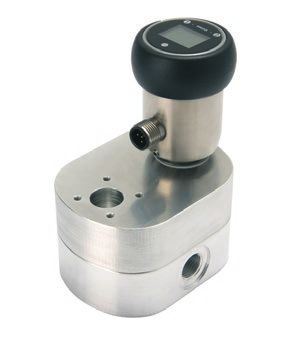
CARACTÉRISTIQUES TECHNIQUES                                  TECHNICAL DATA                                          3

                                   EF 0.04          EF 0.1           EF 0.4             EF 2            EF 4
Plage de débit l/min
                                0.05 ... 4        0.1 ... 10        0.2 ... 30       0.5 ... 70      3.0 ... 150
Flow range l/min
Volume élémentaire cm3/lmp
                                    0.04             0.1               0.4              2.0              4.0
Flow volume cm3/pulse
Fréquence (Hz)
                              20.8 ... 1,666.7 16.7 ... 1,666.7 8.3 ... 1,250.0     4.2 ... 583.3   12.5 ... 625.0
Frequency (Hz)
Facteur K (Imp/l)
                              appr. 25,000      appr. 10,000      appr. 2,500        appr. 500       appr. 250
K-Factor (pulse/l)
Précision à 21 mm2/s
                                    2%               2%                2%               2%               3%
Accuracy at 21 mm2/s
Plage de viscosité mm2/s
                                2 ... 2,000      2 ... 2,000       2 ... 5,000       2 ... 7,000    2 ... 10,000
Viscosity range mm2/s
Pression maxi admissible
                              200 bar (2900 psi)
Max. operating pressure
Température fluide
                              0°C ... +80°C (32°F ... 176°F)
Medium temperature
Position de montage           Indifférente
Mounting position             unrestricted
Filtration
                                   20 µm            20 µm            50 µm             50 µm          100 µm
Filtering
Orifices atéraux
                                   G 1/4”          G 3/8”            G 1/2”           G 3/4”            G 1”
Side pipe connection
Poids
                                 0.62 kg           0.70 kg           1.5 kg            1.7 kg         5.24 kg
Weight

MATÉRIAUX                                                    MATERIALS

Corps                  Aluminium
Body                   Aluminium
Roues dentées          Inox 1.4122, EN  GJS - 400 - 15
Gear wheels            Stainless steel 1.4122, (DIN EN 1563)
Paliers                Roulements à billes inox, Lisses DU, Rlts à billes ou lisses en bronze
Bearing                Stainless steel ball bearing, DU sleeve bearing, ball bearing or bronze sleeve bearing
Joints                 FPM (Standard), NBR, PTFE ou EPDM (Option)
Seals                  FPM (standard), NBR, PTFE or EPDM (optional)
VSE EF ECOFLOW DÉBITMÈTRES ALUMINIUM POUR MONTAGE EN LIGNE ALUMINIUM IN-LINE FLOW METER - Sepem permanent
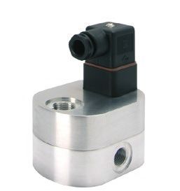
4   DIMENSIONS DES DÉBITMÈTRES                           DIMENSIONS OF FLOW METERS

    EF 0.04                                              EF 0.1

     PG 9                                                     PG 9

                                         95

                                                                                                   97
                                    48

                                                                                              50
                   13

                               12

                                                                                         12
                                                                             14
                               M6                                                        M6

              66                                                      66

             Ø21                                                     Ø23,9

                    G1/4                                                     G3/8

                                                                                         60
                               60

              79                                                      79

    EF 0.4                                               EF 2

              PG 9                                                         PG 9

                   Ø9                                                        Ø9
                                                   106

                                                                                                             117
                                              59

                                                                                                        70
                               17

                                                                                              25

                        Ø29
                        G1/2
                                                                                  Ø35
                                                                                  G3/4
    26

                                                   82

                                                         26
                                              26

                                                                                                             82
                                                                                                        26

                         68

                        109
                                                                                   68

                                                                                  109
5

EF 4                                                         AFFICHEUR LCD DE DÉBIT
                                                             LCD FLOW DISPLAY

                                                                         Ø45
                       PG 9

                                                                M12x1
                                                     155,5

                                                                                       EF 4 = 62
                                                                         Ø35

                                                                                  59
                                               109
                                       36,5

                              X
                  46
            G1                Ø10,5
20

                                      47,5

                                              130
47,5

       46

            179
6   COURBES DES PERTES DE CHARGE                               FLOW RESPONSE CURVES

    EF 0.04                                                    EF 0.1

                                                               Perte de charge ∆ p
    Perte de charge ∆ p

                                                               Flow resistance ∆ p
    Flow resistance ∆ p

                           Durchfluss Q    Flow rate Q                               Durchfluss Q   Flow rate Q

    EF 0.4                                                     EF 2

                                                               Perte de charge ∆ p
    Perte de charge ∆ p

                                                               Flow resistance ∆ p
    Flow resistance ∆ p

                           Débit Q        Flow rate Q                                  Débit Q        Flow rate Q

    EF 4
    Perte de charge ∆ p
    Flow resistance ∆ p

                                                               Viscosité: mm2/s
                          Débit Q         Flow rate Q          Viscosity: mm2/s

    Pour garantir un fonctionnement sûr et sans pertur-         For trouble-free and safe operation of the flow meters,
    bation, il est impératif de sélectionner parfaitement       a correct selection of type and size is decisive. Due to
    le type et la taille du débitmètre. Les caractéristiques    the great number of different applications and flow
    mentionnées dans les catalogues VSE n‘ont qu‘un ca-         meter versions, the technical data in the VSE catalo-
    ractère d‘information, et ne peuvent pas être généra-       gues are of general character. Certain characteristics
    lisées pour toutes les applications. En effet, certaines    of the devices depend on type, size and measuring
    caractéristiques peuvent varier en fonction du type, de     range as well as on the medium to be measured. For
    la taille, de la plage de mesure ainsi que du fluide.       an exact flow meter selection please contact VSE.
    Aussi, n‘hésitez pas à nous contacter pour vous aider
    dans votre choix.
STANDARD: DÉBITMÈTRE                                             STANDARD: VSE EF ECOFLOW FLOW                                    7
VSE EF ECOFLOW, AVEC SORTIE                                      METER, WITH PULSE OUTPUT
IMPULSIONNELLE                                                                        Alimentation
                                                                                      Power supply
                                                                                         0 Volt1
                                                                                                                  +U
                                                                      Sortie                3
                                                                                                    1      Alimentation
                                                                  impulsionnelle                2
                                                                                                          Power supply
                                                                   Pulse output      442
                                                                                        2
                                                                                                        +10R L... 30 Volt/DC
                                                                                                3
                                                                                                                  0V

                                                                                   Assignation des bornes
                                                                                      Pin configuration

DESCRIPTION                                                      DESCRIPTION
La rotation des roues dentées du débitmètre est détectée         The rotation of the flow meter gear wheels is sensed
par un capteur magnéto-résistif sans contact, qui émet un        by a non-contact magnetoresistive pickup, amplified
signal impulsionnel et amplifié. Chaque dent détectée            and emitted as pulses. The passing of each individual
génère une impulsion correspondant très précisément au           gear tooth produces a pulse corresponding to a pre-
volume de fluide deplacé. La sortie impulsionnelle peut          cise positively displaced measured volume. The pulse
être soit de type PNP, soit de type NPN. La fréquence            output can be produced as PNP or NPN signals. The
est alors proportionnelle au débit instantané.                   frequency is proportional to the momentary flow.

SCHÉMA DE CONNEXION                                              CONNECTION DIAGRAM

                             1                                                                  1
                                               +U                                                                +U
                                                                                                            RL
                             2                                                                  2

                     442                                                               442
                                          RL
                              3                                                                 3
                                               0V                                                                0V

Sortie impulsionnelle – Version PNP Pulse output - PNP version   Sortie impulsionnelle - Version NPN Pulse output - NPN version

 Alimentation                       10 ... 30 Volts/DC
 Power supply                       10 ... 30 Volts/DC
 Courant consommé                   18 mA (sans charge)
 Power consumption                  18 mA (no load)
 Sortie impulsionnelle              Commutation PNP ou NPN, 20 mA maxi.
                                    Protection contre les courts-circuits (résistance interne de protection 442 Ω)
                                    Signal carré, 0 ... 1667 Hz, selon la taille du débimètre
 Pulse output                       PNP or NPN switching, 20 mA max.
                                    Short-circuit-proof (internal protective resistor 442 Ω)
                                    Square wave signal, 0 ... 1667 Hz, depending upon flow meter size
 Plage de température               0°C ... +80°C (32°F ... 176°F)
 Temperature range                  0°C ... +80°C (32°F ... 176°F)
 Connexion électrique               suviant DIN EN 175301-803-A
                                    Presse-étoupe pour câble Pg9, Diamètre de câble 6 – 8 mm,
                                    Section maxi des conducteurs 1.5 mm2
 Electrical connection              Square connector according to DIN EN 175301-803-A
                                    Cable gland Pg9, Cable diameter 6 – 8 mm, Wire gauge max. 1.5 mm2
 Protection                         IP 65 (avec connecteur monté)
 Protection class                   IP 65 (with mounted connection plug)
8   OPTION: AFFICHEUR LCD DE DÉBIT                               OPTION: LCD FLOW DISPLAY FOR
    POUR VSE EF ECOFLOW                                          VSE EF ECOFLOW

    AVEC SORTIE ANALOGIQUE ET                                    WITH ANALOGUE OUTPUT AND
    DEUX SEUILS LIMITES                                          TWO LIMIT VALUES

                                                                     Pin 2 - 0/4 ... 20 mA         Pin 1 - +18
                                                                                                           +18 ... 30  Volts/DC
                                                                                                                   30 Volt/DC

                                                                                                       Pin 5 - Seuil   limiteS2S2
                                                                                                               Grenzwert
                                                                                                                 limitvalue
                                                                                                               Limit   value S2
                                                                                                                              S2
                                                                     Pin 3 - 0 Volt                 Pin 4 - Seuil  limiteS1S1
                                                                                                            Grenzwert
                                                                                                             limit value S1
                                                                                                            Limit value S1
                                                                                Assignation   des bornes
                                                                                      Steckerbelegung
                                                                                   Pinpinconfiguration
                                                                                          configuration

    DESCRIPTION                                                  DESCRIPTION
    L‘afficheur de débit programmable analyse les im-            The programmable flow display evaluates the pulses
    pulsions délivrées par le capteur magnéto-résistif, et       from the magnetoresistive pickup and shows the
    affiche le débit dans l‘unité choisie sur un écran LCD       chosen units on a backlit LCD-display. Alarm and con-
    rétro-éclairé. Une LED rouge et un texte additionnel in-     dition reports are signalled in the display by a red LED
    diquent tout défaut ou rapport de fonctionnement. La         with additional text. The measured values are trans-
    valeur mesurée peut être récupérée via une sortie ana-       mitted by means of an analogue output, 0 or 4 up
    logique 0/4 ... 20 mA, ou 0/2 ... 10 Volt au moyen           to 20 mA, and 0 or 2 up to 10 Volt by means of a
    d‘une résistance (500 Ω). Deux sorties transistors per-      resistor (500 Ohm). The limit values are signalled
    mettent d‘exploiter les seuils limites.                      through two transistor switching outputs.

    SCHÉMA DE CONNEXION                                          CONNECTION DIAGRAM

                                                   1
                                     DC                                                 +U
                     Display
                                          DC       3
                                                                                        0V
                                                                           RL
                                                                         500
                                                                                        (0/2...10 V)
                                      D            2
                                                                                        0/4...20 mA
                                          A
        Sensor                                                 RL
                        µC                 +                   PNP
                                                   4
                                                                                        S1
                                                   5
                                                                                        S2
                                                                 RL
                                                                 NPN
9

Ecran                                  Afficheur LCD à 4 digits rétro-éclairé;
                                       Affichage de la valeur mesurée et de l‘unité du débit Signalement de
                                       défaut de fonctionnement par LED rouge
Graphic display                        LCD display, 4-digit with backlit;
                                       shows value, dimension and dialogue-message;
                                       red, flashing LED indicator
Sortie analogique                      0/4 ... 20 mA; convertisseur A/N 12 bits
                                       (0/2 ...10 Volt, avec résistance externe 500 Ω)
Analogue output                        0 or 4 ... 20 mA; 12 bit A/D converter
                                       (0 or 2 ... 10 Volt, with external 500 Ω resistor)
Seuils limites                         S1 et S2; sortie transistor 30V/100 mA maxi
                                       Sortie push-pull, PNP ou NPN en fonction de la connexion externe.
                                       Protection contre les courts-circuits et les inversions de polarité.
                                       Hystérésis réglable, valeur et direction.
Switch points                          S1 and S2; Transistor output 30 V/100 mA max.
                                       Push-pull output, PNP or NPN selectable with external connection
                                       Short-circuit proof and reverse-polarity proof
                                       Hysteresis adjustable in value and direction
Alimentation                           18 ... 30 Volt DC/
10   CODIFICATION                                                   TYPE CODE

                                                     EF . . . . . . - . /.

     Taille       0.05 … 		 4 l/min.        = 0.04                             = Indice (n° constructeur) 1
     Size         0.1 … 10 l/min.           = 0.1                              = Series (factory preset) 1
                  0.2 … 30 l/min.           = 0.4
                                                                             PNP         = Sortie impulsionnelle PNP
                  0.5 … 70 l/min.           =2
                                                                             NPN         = Sortie impulsionnelle NPN
                  3.0 … 150 l/min.          =4
                                                                             LCD         = Afficheur de débit LCD
     Matériaux    Aluminium (Standard)      =A                               PNP         = Pulse output PNP
     Material     Aluminium (standard)      =A                               NPN         = Pulse output NPN
                                                                             LCD         = LCD-Flow Display
     Raccorde-    Sur embase                =P
     ment         En ligne                  =R
     Connection Subplate                    =P
     type       Piping                      =R

     Version      Standard                  =0
                  Avec fenêtre de           =2
                  visualisation
     Version      Standard                  =0
                  With sight glass          =2

     Type de      Roulements à billes       =1
     paliers                                                          Rappel sur la matière des joints toriques
                  Paliers lisses bronze     =3
                                                                      FPM (> FKM) = Fluor Carbone
                  Paliers lisses DU         =6
                                                                      NBR           = Acrylique Nitrile Butadiène
     Gear         Ball bearing              =1
     bearings                                                         PTFE          = Poly Tétra Fluor Ethylène
                  Bronze sleeve bearing     =3
                                                                      EPDM          = Ethylène Propylène Diène
                  DU sleeve bearing         =6
                                                                      Short term explanation to type of seals
     Tolérances Tolérances réduites         =1
     de denture Tolérances normales                                   FPM (> FKM) = Fluorine carbon rubber O-ring
                                            =2
                                                                      NBR           = Acrylnitrile butadiene rubber O-ring
                  Tolérances augmentées     =3
                                                                      PTFE          = Polytetrafluorethylene rubber O-ring
                  Tolérances pour paliers   =4
                  lisses                                              EPDM          = Ethylen propylene diene rubber O-ring
     Gear         Reduced tolerance         =1
     tolerance    Normal tolerance          =2                           Autres n° = éxecution spéciales
                  Increased tolerance       =3                           Éxecution spéciales sur demande
                  Tolerance sleeve bearing = 4                           Déterminées par le constructeur
                                                                         suivant l´application
     Type de      FPM (≥ FKM) Standard = V
     joints                                                              Other type no. = special design
                  NBR                  =P
                                                                         Special design upon request
     Seal type    PTFE                      =T
                                                                         Factory preset to the application
                  EPDM                      =E
APERÇU DE LA GAMME                                                           11
PRODUCT OVERVIEW

                                    SÉRIE RS               0 – 3,000 l/min
                                    RS SERIES

SÉRIE VSI      0.002 – 525 l/min    SÉRIE VHM              0.01 – 20 l/min
VSI SERIES                          VHM SERIES

SÉRIE VTR    110 l/h – 4,500 m³/h   EXÉCUTIONS SPÉCIALES
VTR SERIES                          SPECIAL OPTIONS
VSE Volumentechnik GmbH
                                            Hönnestraße 49
                                            58809 Neuenrade / Germany
                Suco VSE France
                ZAC de l'Oseraie            VSE Volumentechnik GmbH
                6 rue Jacques Offenbach     Postfach/P.O.Box 1229
                72000 Le Mans / France      58804 Neuenrade / Germany
                                                                                               01/18 www.plakart.de

                Tél. +33 (0)2 43 14 14 21   Phone +49 (0) 23 94 / 616-30
                Fax +33 (0)2 43 14 14 25    Fax    +49 (0) 23 94 / 616-33
                info@sucovse.fr             info@vse-flow.com
distribué par
                www.sucovse.fr              www.vse-flow.com                 www.e-holding.de
Vous pouvez aussi lire