HGT 1035 Handheld Control Panel - Operating Manual - SIGMATEK
←
→
Transcription du contenu de la page
Si votre navigateur ne rend pas la page correctement, lisez s'il vous plaît le contenu de la page ci-dessous

HGT 1035
             Handheld Control Panel

                               Operating Manual

Date of creation: 10.12.2013     Version date: 26.02.2021   Article number: 01-245-1035-E
Publisher: SIGMATEK GmbH & Co KG
                                   A-5112 Lamprechtshausen
                                      Tel.: +43/6274/4321
                                    Fax: +43/6274/4321-18
                                   Email: office@sigmatek.at
                               WWW.SIGMATEK-AUTOMATION.COM

                                               Copyright © 2013
                                            SIGMATEK GmbH & Co KG

                                      Translation from German

All rights reserved. No part of this work may be reproduced, edited using an electronic system, duplicated or dis-
tributed in any form (print, photocopy, microfilm or in any other process) without the express permission.

We reserve the right to make changes in the content without notice. The SIGMATEK GmbH & Co KG is not responsi-
ble for technical or printing errors in the handbook and assumes no responsibility for damages that occur through
use of this handbook.
10.4“ HANDHELD CONTROL PANEL                HGT 1035

10.4" Handheld Control Panel                                               HGT 1035

The HGT 1035 Control Panel is an intelligent handheld control panel used for programming
and visualization of automated processes. Process diagnosis, operating and monitoring
functions are thereby simplified.

A touch screen serves as the input medium for process data and parameters. The output is
shown on a 10.4" XGA TFT color display.

With the LSE mask editor, graphics can be created on the PC, then stored and displayed
on the terminal.

The available interfaces can be used to exchange process data or configure the handheld
control panel. On the Flash card, the operating system, application and application data are
stored.

26.02.2021                                                                          Page 1
HGT 1035         10.4“ HANDHELD CONTROL PANEL

Contents
1    Essential Components ........................................................... 4

2    Basic Safety Guidelines ......................................................... 5
     2.1         Symbols Used ............................................................................... 5

     2.2         General Safety Guidelines ........................................................... 7

     2.3         Designated Use ............................................................................. 8

     2.4         Residual Risks ............................................................................ 11

     2.5         Safety of the Machine or Equipment ........................................ 12

3    Technical Data .......................................................................14
     3.1         Performance Data ....................................................................... 14

     3.2         Electrical Requirements ............................................................. 15

     3.3         Terminal ....................................................................................... 16

     3.4         Environmental Conditions ......................................................... 17

     3.5         Display ......................................................................................... 17

     3.6         Terminal Requirements .............................................................. 17

     3.7         Miscellaneous ............................................................................. 18

4    Mechanical Dimensions ........................................................19
     4.1         Wall Mounting ............................................................................. 20

5    Interfaces ................................................................................21
     5.1         Rear Connectors ......................................................................... 21

     5.2         Key Switch ................................................................................... 23

     5.3         Confirmation Switch ................................................................... 23
Page 2                                                                                               26.02.2021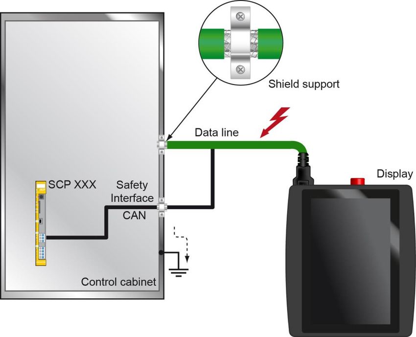
10.4“ HANDHELD CONTROL PANEL HGT 1035
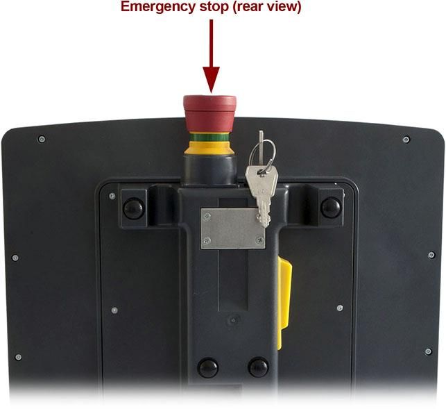
5.4 Emergency Stop.......................................................................... 24
6 Storage Media ........................................................................ 25
7 Wiring Guidelines .................................................................. 25
7.1 ESD Protection ............................................................................ 25
7.2 USB Interface Connections ....................................................... 25
8 Accessory Wall-Mount .......................................................... 26
8.1 Mechanical Dimensions ............................................................. 27
9 Cleaning the Touch Screen .................................................. 28
10 Recommended Cable Shielding ........................................... 29
10.1 Connection from the Control Cabinet to the HGT ................... 29
26.02.2021 Page 3
HGT 1035          10.4“ HANDHELD CONTROL PANEL

1    Essential Components

•   10.4" SVGA TFT color display with backlighting

•   10.4" Touch screen

•   Confirmation switch (mounted on the rear side), 2-channel configuration

•   Key switch (mounted top-center), 2-channel wiring

•   Emergency Stop switch (mounted top center), 2-channel wiring

•   USB socket with cover

•   M16 connector with special cable (swivels 90°)

•   Applicable safety controls:
     - SCP XXX

Page 4                                                                        26.02.2021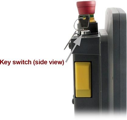
10.4“ HANDHELD CONTROL PANEL                  HGT 1035

2     Basic Safety Guidelines
2.1    Symbols Used

For warning, danger messages and informational notes, the following symbols are used in
the operator documentation:

             DANGER                DANGER
                                   Identifies an immediate danger with high risk, which
                                   can lead to immediate death or serious injury if not
                                   avoided.
                                   Indique un danger direct à haut risque d’un décès
                                   immédiat ou des blessures graves si les consignes de
                                   sécurité ne sont pas respectées.

             WARNING               WARNING

                                   Identifies a possible danger with a mid-level risk,
                                   which can lead to death or (serious) injury if not
                                   avoided.

                                   Indique un danger possible d’un risque moyen de
                                   décès ou de (graves) blessures si les consignes de
                                   sécurité ne sont pas respectées.

             CAUTION               CAUTION
                                   Identifies a low risk danger, which can lead to injury or
                                   property damage if not avoided.
                                   Indique un danger avec un niveau de risque faible des
                                   blessures légères ou des dommages matériels si les
                                   consignes de sécurité ne sont pas respectées.

                                   Danger for ESD-sensitive components

                                   Les signes de danger pour les composants sensibles
                                   aux décharges électrostatiques

26.02.2021                                                                          Page 5
HGT 1035 10.4“ HANDHELD CONTROL PANEL
This symbol identifies important or additional infor-
mation regarding the operation of the safety modules.
Ce symbole indique des informations importantes ou
supplémentaires concernant le fonctionnement des
modules de sécurité particuliers.
INFORMATION
Provides user tips, informs of special features and
identifies especially important information in the text.
Page 6 26.02.202110.4“ HANDHELD CONTROL PANEL HGT 1035
2.2 General Safety Guidelines
According to the EU guideline 2006/42/EG, the operating instructions are a
component of a product.
This handbook must therefore be accessible in the vicinity of the machine,
since it contains important instructions.
The technical documentation should be included in the sale, rental or transfer
of the product.
Please read the corresponding data sheets and operating instructions thor-
oughly before handling Safety modules. SIGMATEK is not liable for damages
caused through non-compliance with these instructions or respective regula-
tions.
The general and special safety instructions described in the following sec-
tions, as well as technical regulations, must therefore be observed.
Subject to technical changes, which improve the performance of the devices.
The following documentation represents a series of product descriptions and
does not serve to guarantee properties under the warranty.
In regard to the requirements for Safety and health connected to the use of
machines, the manufacturer must perform a risk assessment in accordance
with machine guidelines 2006/42/EG before bringing a machine to the mar-
ket.
26.02.2021 Page 7HGT 1035 10.4“ HANDHELD CONTROL PANEL
2.3 Designated Use
The Safety functions implemented in the Safety modules are designed for use with safety-
related applications in a PLC control and meet the required conditions for safe operation in
SIL 3 or SIL CL 3 according to EN 62061 and in compliance with PL e. Cat. 4 in accordance
with EN ISO 13849-1.
The instructions contained in this document must be followed.
Safety functions can only be powered by supplies that meet the require-
ments for PELV in compliance with EN60204.
For error-free operation, proper transport and storage are essential.
Installation, mounting, programming, initial start-up, operation, maintenance
and discarding of the Safety module can only be performed by qualified
personnel.
Qualified personnel in this context are people who have completed training
or have trained under supervision of qualified personnel and have been
authorized to operate and maintain safety-related equipment, systems and
facilities in compliance with the strict guidelines and standards of safety
technology. The applicable environmental conditions must be maintained.
Les instructions de cette documentation doivent être respectées.
Les composants de sécurité ne doivent être alimentés que par des alimenta-
tions conformes aux exigences PELV selon la norme EN60204.
Un transport et un stockage approprié sont essentiels au bon fonctionne-
ment.
L'installation, le montage, la programmation, la mise en service, l'exploita-
tion, la maintenance et la mise hors service des modules de sécurité ne
doivent être effectués que par du personnel qualifié.
En ce sens, les personnes qualifiées sont des personnes ayant acquis la
formation respective ou étant formées par un spécialiste pour superviser des
dispositifs, systèmes et systèmes de sécurité conformément aux directives
et normes de sécurité applicables. Les conditions environnementales appli-
cables doivent être respectées.
Page 8 26.02.202110.4“ HANDHELD CONTROL PANEL HGT 1035
For your own safety and the safety of others, the safety modules
should be used for their designated purpose only.
Correct EMC installation is also included under designated use.
Utilisez les modules de sécurité pour votre sécurité et celle des autres
uniquement d’une façon appropriée.
Une utilisation appropriée inclut également une installation conforme à
la compatibilité électromagnétique.
Non-designated use consists of
Any changes made to the Safety modules or the use of damaged modules.
The use of the Safety modules outside of technical margins described in
these operating instructions.
The use of the Safety modules outside of the technical data described in
these operating instructions (see the "Technical data" sections of the re-
spective product documentation).
Sont considérés comme inappropriés
Toute modification de quelque nature que ce soit faite aux modules de sécu-
rité ou l'utilisation de modules de sécurité endommagés.
L’utilisation de modules de sécurité en dehors du cadre technique décrit
dans ce manuel
L’utilisation des modules de sécurité en dehors des données techniques
décrites dans ce mode d'emploi (voir également les sections « Caractéris-
tiques techniques » dans la documentation correspondante).
26.02.2021 Page 9HGT 1035 10.4“ HANDHELD CONTROL PANEL
In addition, the Safety Guidelines in the other sections of these instruc-
tions must be observed. These instructions are visibly emphasized by
symbols.
Veillez à bien respecter les consignes de sécurité dans les autres sec-
tions de ce manuel. Ces notes sont visuellement mises en évidence
par des symboles.
Regarding electrical safety, the requirements of the EN 61131-2 standard
apply. For the machine and the entire installation, further norms and guide-
lines apply. For example, the EN 60204-1.
For your own safety and that of others, compliance with the environmental
conditions is essential.
The control cabinet and the module carrier must be connected to earth cor-
rectly.
For maintenance and repairs, disconnect the system from the power supply.
En ce qui concerne la sécurité électrique, les exigences de la norme EN
61131-2 pour l'unité de commande portative s'appliquent. La machine et
l'ensemble de l'installation peuvent être soumises à d'autres normes et ré-
glementations, telles que la norme EN 60204-1.
Pour votre propre sécurité et pour la sécurité des autres, assurez-vous du
respect des conditions environnementales.
L'armoire de commande et le support de modules doivent avoir un contact
de mise à la terre correct.
Débranchez toujours le système du secteur lors de l'entretien et des répara-
tions.
Page 10 26.02.202110.4“ HANDHELD CONTROL PANEL HGT 1035
2.4 Residual Risks
In the risk assessment defined by the 2006/42/EG guideline (machine
guideline), the machine manufacturer must include the possible resid-
ual risks posed by Safety modules. These include:
Unwanted movements of driven machine components
Unwanted temperatures, emissions of gas, particles, smell and light.
Dangerous contact voltages
The effects of electrical, magnetic and electromagnetic fields produced
during operation (for example, on pacemakers and implants)
Possible effects of information technology devices (cell/smart phones
etc.)
Release of non-environmentally compatible substances and emissions
Dans l'évaluation des risques définis par la Directive Machines
2006/42/CE le fabricant de la machine doit inclure les éventuels risques
résiduels posés par les modules Safety. Ceux-ci comprennent:
Mouvements involontaires des pièces entraînées de la machine.
Températures non désirées, les émissions de gaz, les particules,
l'odeur et la lumière.
Tensions de contact dangereuses
Les effets des champs électriques, magnétiques et électromagnétiques
produites pendant le fonctionnement (par exemple, sur les stimu-
lateurs cardiaques et les implants).
Les effets possibles sur les dispositifs de technologie de l'information
(téléphones cellulaires / téléphones intelligents, etc.)
Dégagement de substances et d'émissions non respectueux de l'envi-
ronnement.
26.02.2021 Page 11HGT 1035 10.4“ HANDHELD CONTROL PANEL
2.5 Safety of the Machine or Equipment
Strict compliance with the safety guidelines is required, otherwise all warranties and claims
are invalid:
Observe all on-site rules and regulations for accident prevention and occupa-
tional safety.
2.6 Conformity with EU Standards
The components were constructed in compliance with the following European Union guide-
lines
2006/42/EG Machine guideline
2014/35/EU Low-voltage guideline
2014/30/EU EMV guideline
2011/65/EU RoHS guideline
2.7 Functional Safety Standards
Emergency stop switch und confirmation switch:
- EN 62061 SIL 3 or SIL CL 3
- EN ISO 13849-1/-2 PL e / CAT 4
Page 12 26.02.202110.4“ HANDHELD CONTROL PANEL HGT 1035
2.8 Safety-relevant Parameters
The use of the specified parameters requires a risk analysis of the end application.
Input module Safety parameters (*)
HGT 1035 PFHD = 1.1E-11 (1/h)
Including Safe CPU (SCP XXX) MTTFD = 306 years
DC = 99 %
Confirmation switch B10D = 100,000
Key switch B10D = 10,000
Emergency stop switch B10D = 325,000
(*) Depending on the application, the probability of failure must be determined for the included electromechanical
components based on the B10D values listed here and included in the calculation for the entire system.
26.02.2021 Page 13HGT 1035 10.4“ HANDHELD CONTROL PANEL
3 Technical Data
3.1 Performance Data
Processor EDGE2-Technology
Processor core 21)
Internal cache 32-kbyte L1 instruction cache
32-kbyte L1 data cache
512-Kbyte L2 cache
Internal program and 256-Mbyte
data memory (DDR3 RAM)
Internal remnant 128-kbyte MRAM
data memory
Internal storage device 1024-Mbyte microSD card
Internal I/O no
Interfaces 1x Ethernet
1x USB 2.0 Type A
1x Safety Interface2)
1x VARAN
Internal interface connections 1x TFT LCD color display
and devices 1x touch
Control panel touch screen (analog resistive)
confirmation switch (2 normally open, 3-stage)
key switch (2 normally open)
emergency stop switch (2 normally closed)
Display 10.4" TFT color display
Resolution 1024 x 768 pixels
Control panel 5-wire touch screen (analog resistive)
Signal generator no
Real-time clock yes (buffering approximately 10 days)
Cooling Passive (fanless)
1)
Attention: When programming (with LASAL) on multicore CPUs, particular focus must be placed on thread security!
2)
The Safety Interface must be used exclusively with the SIGMATEK SCP XXX!
The status of the safety-related inputs (confirmation switch, key switch, emergency stop switch) is sent to the SCP
XXX.
The function of the key switch, confirmation switch and emergency stop switch must be tested at least once per
month!
Page 14 26.02.202110.4“ HANDHELD CONTROL PANEL HGT 1035
2)
L'interface de sécurité doit uniquement être utilisée avec le SIGMATEK SCP XXX! L'état des entrées de sécurité
(interrupteur de validation, interrupteur à clé, interrupteur d'arrêt d'urgence) est transmis au SCP XXX.
L'interrupteur à clé, l'interrupteur de confirmation et de l'interrupteur d'arrêt d'urgence doivent être vérifiés au moins
une fois par mois !
3.2 Electrical Requirements
Supply voltage typically +24 V DC (PELV)
minimum +24 V DC (PELV) maximum +30 V DC (PELV)
Supply voltage (UL) +24-30 V DC (NEC Class 2 or LVLC)
Current consumption typically 0.5 A typically 0.6 A
Power supply +24 V (without externally connected devices) (with external devices connected)
Protection class III
Inrush current maximum 10 A for < 50 ms
USB current load maximum 0.5 A
26.02.2021 Page 15HGT 1035 10.4“ HANDHELD CONTROL PANEL
For USA and Canada:
The supply must be limited to:
a) max. 5 A at voltages from 0-20 V (0-28.3 Vp) or
b) 100 VA at voltages from 20-30 V (28.3-42.4 Vp)
The limiting component (e.g. transformer, power supply or fuse) must be certified by
an NRTL (Nationally Recognized Testing Laboratory).
Pour les États-Unis et le Canada:
L’alimentation doit être limitée à:
a) max. 5 A pour des tensions de 0-20 V (0-28,3 Vp), ou
b) 100 VA pour des tensions de 20-30 V (28,3-42,4 Vp)
Le composant imposant la limite (par exemple, transformateur, alimentation élec-
trique ou fusible) doit être certifié par un NRTL (National Recognized Testing Labora-
tory, par exemple, UL).
3.3 Terminal
Dimensions 264 x 226 x 73.3 mm (W x H x D)
(without key switch)
Material housing: PC/ASA
color: RAL7024
Weight typically, circa 1.1 kg without connector cable
Page 16 26.02.202110.4“ HANDHELD CONTROL PANEL HGT 1035
3.4 Environmental Conditions
Storage temperature -10 … +60 °C
Environmental temperature 0 …+50 °C
Humidity 10-95 %, non-condensing
Operating conditions pollution degree 2
altitude up to 2000 m
EMC stability EN 61000-6-2 (industrial area)
(increased requirements according to IEC/EN 62061)
Shock resistance EN 60068-2-27 150 m/s²
Vibration resistance 10 m/s²
Protection type EN 60529 IP54
(only with all protective caps fitted)
Free fall DIN EN 60068-2-31 500 mm
(without packaging)
3.5 Display
Type 10.4” TFT LCD color display
Resolution XGA, 1024 x 768 pixels
Color depth 18-bit RGB (262K colors)
LCD mode normal black
LCD Polarizer transmissive
Pixel size 0.0685 x 0.2055 mm
Backlighting LED
Contrast typically 1000: 1
Brightness typically 350 cd/m²
Angle CR ≥ 10 88° from all sides
3.6 Terminal Requirements
Connection technology M16 plug (see X2 on page 22)
special connector cable
minimum bend radius: 147 mm
26.02.2021 Page 17HGT 1035 10.4“ HANDHELD CONTROL PANEL
3.7 Miscellaneous
Article number 01-245-1035
Hardware version 1.x
Connector cable optionally available (see documentation for connection cables for operating
devices)
Standard UL 508 (E247993)
Approvals CE, TÜV EC type tested, cULUS
Page 18 26.02.202110.4“ HANDHELD CONTROL PANEL HGT 1035 4 Mechanical Dimensions 26.02.2021 Page 19
HGT 1035      10.4“ HANDHELD CONTROL PANEL

4.1   Wall Mounting

Page 20                                      26.02.2021
10.4“ HANDHELD CONTROL PANEL             HGT 1035

5     Interfaces
5.1    Rear Connectors

X1: USB Interface Connections 2.0 Type A

                              Pin              Function
                               1                 +5 V
                               2                  D-
                               3                  D+
                               4                 GND

 It should be noted that many of the USB devices on the market do not comply with
   USB specifications; this can lead to device malfunctions. It is also possible that
these devices will not be detected at the USB port or function correctly. Therefore, it
          is recommended that every USB stick be tested before actual use.

26.02.2021                                                                     Page 21
HGT 1035 10.4“ HANDHELD CONTROL PANEL
X2: Cable Connector M16
Pin Wire color Function
L Yellow Safety Interface-H
J Green Safety Interface-L
G Black Safety Interface shield
E Red +24 V DC
C Black GND
A Shield ETH shield
U White ETH_TX+
T Red VAR_RX+
S Blue VAR_RX-
R Pink VAR_TX+
P Gray VAR_TX-
O Yellow ETH_RX-
N Green ETH_RX+
M Brown ETH_TX-
The appropriate connector cables are optionally available.
See documentation for connection cables operating devices.
The handheld control panel can only be operated with
the SCP XXX Safety module!
As required by EN ISO 13850, section 4.1 and EN 60204-1, section 10.7.1, it
must be impossible to confuse a functioning handheld control panel with a
non-functioning one.
Note on the Emergency Stop function: A non-connected HGT 1035 does not
have to be visibly sealed!
LED
LED status Definition
LED lights green DC OK
Page 22 26.02.202110.4“ HANDHELD CONTROL PANEL HGT 1035
5.2 Key Switch
The key switch is two-stage and read via the SCP XXX connected to the Safety Interface. In
the SCP XXX, the "HGB0811_K class is used; inputs 5 and 6 are assigned to the key
switch.
5.3 Confirmation Switch
The confirmation switch is three-stage. If the switch is not pressed or pressed only partially,
it is inactive. The switch is active when simply pressed (middle stage). In the SCP XXX, the
"HGB0811_K class is used; inputs 1 and 2 are assigned to the confirmation switch.
With the "HGT1035" hardware class, the safety number of the connected SCP XXX
among other things, can be evaluated in the HGT 1035.
26.02.2021 Page 23HGT 1035 10.4“ HANDHELD CONTROL PANEL 5.4 Emergency Stop The Emergency stop is 2-channel. In the SCP XXX, the "HBG0811_K" module is used with the inputs 3 and 4. Page 24 26.02.2021
10.4“ HANDHELD CONTROL PANEL                 HGT 1035

6      Storage Media
           It is recommended that only storage media provided by SIGMATEK
                    (CompactFlash cards, microSD cards etc.) be used.
         The number of read and write actions have a significant influence on the
                             lifespan of the storage media.

      The microSD card is not meant to be used as a removable media and thus only
           should be removed from the card holder for maintenance purposes.

7      Wiring Guidelines
7.1      ESD Protection

Typically, USB devices (keyboard, mouse...) are not equipped with shielded cables. These
devices are disrupted by ESD and in some instances, no longer function.

Before any device is connected to, or disconnected from the terminal, the potential should
be equalized (by touching the control cabinet or earth terminal). This will allow the dissipa-
tion of electrostatic loads (caused by clothing/shoes).

7.2      USB Interface Connections

The handheld control panel has a USB interface. The terminal has a USB interface connec-
tion that can be used to connect various USB devices (keyboard, mouse, storage media,
hubs, etc.).

26.02.2021                                                                           Page 25
HGT 1035 10.4“ HANDHELD CONTROL PANEL
8 Accessory Wall-Mount
The corresponding wall-mount is available from SIGMATEK under the
article number 01-245-1035-Z1.
Page 26 26.02.202110.4“ HANDHELD CONTROL PANEL HGT 1035 8.1 Mechanical Dimensions 26.02.2021 Page 27
HGT 1035          10.4“ HANDHELD CONTROL PANEL

9    Cleaning the Touch Screen
                                         CAUTION!
              Before cleaning the touch screen, the HGT must be turned off
          in order to prevent triggering functions or commands unintentionally!

The HGT touch screen can only be cleaned using a soft damp cloth. To dampen the cloth,
a screen cleaning solution such as antistatic foam cleaner, water with detergent or alcohol
is recommended. To avoid fluids/cleaning solutions from getting into the housing, the HGT
should not be sprayed directly. For cleaning, no erosive cleaning solutions, chemicals,
abrasive cleansers or hard objects that can scratch or damage the touch screen may be
used.

If the HBT is contaminated with toxic or erosive chemicals, it must be carefully cleaned as
quickly as possible to prevent acid burns!

    To ensure the optimal function of the HGT, the touch screen should be cleaned
                                 in regular intervals!

            To avoid damaging the touch screen, using either the fingers or
                    a stylus to operate the panel is recommended.

Page 28                                                                        26.02.2021
10.4“ HANDHELD CONTROL PANEL HGT 1035 10 Recommended Cable Shielding For applications in which the bus is operated outside the control cabinet, the correct shield- ing is required. Especially when for structural reasons, the bus line must be placed next to sources of strong electromagnetic interference. It is recommended that wiring the connector cable in parallel with power cables be avoided whenever possible. 10.1 Connection from the Control Cabinet to the HGT It is recommended that the shielding be mounted at the entry point of the control cabinet housing. Noise can then be deflected from the electronic components before reaching the module. 26.02.2021 Page 29
HGT 1035             10.4“ HANDHELD CONTROL PANEL

Documentation Changes

Change       Affected   Chapter                          Note
date         page(s)

29.09.2014   12         3.2 Electrical Requirements      Added Supply voltage (UL) and notice in grey box

             14         3.7 Miscellaneous                Added Standard

29.12.2014   16         4.1 Wall Mounting                Added Wall Mounting

09.03.2015   23         8. Accessory Wall-Mount          Added Accessory Wall-Mount

12.03.2015   12         3.2 Electrical Requirements      Changed Supply voltage (UL)

             5          2.1 Symbols Used                 Safety Guidelines format

24.03.2015   20-21      5.2 Connector Cable Layout       Added Connector Cable Layout

             15         3.6 Terminal Requirements        Added special connector cable

             15         3.7 Miscellaneous                Added connector cable

08.09.2015                                               Changed to general SCP

29.09.2015   13         3.2 Electrical Requirements      Added LVLC at Supply voltage (UL) line of the table

05.10.2015   15         3.7 Miscellaneous                UL, cUL, CE added

19.04.2016   12         3.1 Performance Data             Table updated

27.06.2016                                               CAN -> Safety Interface

13.09.2016   24         6 Storage Media                  Note microSD

08.02.2017   20         5.2 Connector Cable Layout       Graphic article number

26.09.2017   15         3.5 Terminal Requirements        Added cable specifications
                        3.6 Miscellaneous                Added article numbers

             20         5.2 Connector Cable Layout       Length detail removed, replaced picture

29.09.2017   26         8.1 Mechanical Dimensions        Chapter added

08.03.2018              Document                         Changes due to safety recertification

             11         2.8 Safety-relevant Parameters   Emergency Stop switch changed

             15         3.6 Terminal Requirements        Connection technology

                        3.7 Miscellaneous                Connector cable

                        5.2 Connector Cable Layout       deleted

16.08.2018   15         3.1 Performance Data             Note corrected

Page 30                                                                                            26.02.2021
10.4“ HANDHELD CONTROL PANEL HGT 1035
17.12.2019 10.1 Connection from the Graphics extended
Control Cabinet
08.09.2020 15 3.2 Electrical Requirements Protection class added
17 3.4 Environmental Conditions Added for Protection type (only with all protective caps
fitted)
18.11.2020 14 3.1 Performance Data Footnote cores (programming) added
26.02.2021 13 2.8 Safety-relevant Parameters PFHD und DC values changed
26.02.2021 Page 31HGT 1035 10.4“ HANDHELD CONTROL PANEL Page 32 26.02.2021
Vous pouvez aussi lire