Installation and User's Guide - Automatic Pool Cleaner - IMPORTANT SAFETY INSTRUCTIONS READ AND FOLLOW ALL INSTRUCTIONS SAVE THESE INSTRUCTIONS
←
→
Transcription du contenu de la page
Si votre navigateur ne rend pas la page correctement, lisez s'il vous plaît le contenu de la page ci-dessous
Automatic Pool Cleaner

                           Installation and
                             User’s Guide

IMPORTANT SAFETY INSTRUCTIONS
READ AND FOLLOW ALL INSTRUCTIONS
SAVE THESE INSTRUCTIONS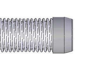
Technical Support
                Sanford, North Carolina (8 A.M. to 5 P.M.)

                Moorpark, California (8 A.M. to 5 P.M.)

                Phone: (800) 831-7133

                Fax: (800) 284-4151

Web sites: visit www.pentairpool.com and staritepool.com

© 2011 Pentair Water Pool and Spa, Inc. All rights reserved

This document is subject to change without notice

1620 Hawkins Ave., Sanford, NC 27330 • (919) 566-8000
10951 West Los Angeles Ave., Moorpark, CA 93021 • (805) 553-5000

Trademarks and Disclaimers:
Great White® and Pentair Water Pool and Spa® are registered trademarks of Pentair Water Pool and Spa, Inc.
and/or its affiliated companies in the United States and/or other counties. Unless noted, names and brands of
others that may be used in this document are not used to indicate an affiliation or endorsement between the
proprietors of these names and brands and Pentair Water Pool and Spa, Inc. Those names and brands may be the
trademarks or registered trademarks of those parties or others.
PN789 (Rev C) - 1/24/11
i
Contents
Important Safety Precautions .............................................................................. ii
Section 1: Overview ............................................................................................ 1
Preparation of your pool ............................................................................... 2
Cleaner assembly ............................................................................ 2
Hose Assembly ................................................................................ 3
Section 2: Installation .......................................................................................... 5
Standard Installation ..................................................................................... 5
Optional Installation ...................................................................................... 8
Section 3: Operation ............................................................................................ 11
Cleaner Operation and Movement ............................................................... 11
Clicking sound ................................................................................ 11
Movement around the pool ............................................................... 11
Picks up “big stuff” ....................................................................................... 11
Fine-tuning valves and connections ............................................................ 12
Valves (pump, skimmer, and main drain) and vacuum adjustments 12
Too much vacuum? ......................................................................... 12
Not enough vacuum? ....................................................................... 12
In-Line leaf canisters ........................................................................ 13
Skimmer connection ........................................................................ 13
Skimmer vac plates ......................................................................... 13
Skimmer vac plate vacuum control adjusters .................................. 13
Section 4: User Maintenance ............................................................................. 15
Hose Storage ............................................................................................... 15
Disassembly ................................................................................................ 16
Reassembly ................................................................................................ 17
Illustrated Parts List ..................................................................................... 18
Section 5: Troubleshooting ................................................................................ 19
Great White Installation and User’s Guideii
IMPORTANT SAFETY PRECAUTIONS
Important Notice:
Attention Installer: This manual contains important information about the installation, operation and safe use
of this product. This information should be given to the owner and/or operator of this equipment.
WARNING — Before installing this product, read and follow all warning notices and instructions which
are included. Failure to follow safety warnings and instructions can result in severe injury,
death, or property damage. Call (800) 831-7133 for additional free copies of these
instructions.
WARNING — Hazardous suction. Can trap and tear hair or body parts. Can cause drowning.
Do not play with cleaner or hose or apply to body. Do not let children use or play
with pool cleaner. Stop pump before attempting to clean unit.
CAUTION — Oscillator may injure hands or fingers. Stop pump before attempting to clean out
pool cleaner head.
1058 0594
WARNING — Hose can trip or entangle swimmers. Do not allow swimmers in pool while pool cleaner
is operating.
General Installation Information
Pre-installation check list
Before installing the cleaner in a vinyl liner pool:
Check liner closely for signs of deterioration or damage from age, chemicals, pool wall damage, etc. If any
damage is found, have a qualified pool professional make all necessary repairs. Also, if there are stones, roots,
etc., under the liner, remove them before installing the cleaner.
Before installing the cleaner in a gunite pool or a pool that is partially or completely tiled:
Repair loose tiles and tighten any loose light rings.
Before installing the cleaner, clean your filter system:
Make sure you have cleaned the filter, including backwashing, rinsing, and emptying all baskets. A clean
system is necessary for proper cleaner operation and coverage.
Great White Installation and User’s Guideiii
IMPORTANT SAFETY PRECAUTIONS (continued)
General Installation Information (continued)
Before installing the cleaner, fill the hose with water:
Always make sure the cleaner head is submerged and the hose is full of water before connecting the hose to
the filtration system (whether through a skimmer or dedicated wall fitting). Air in the system can damage the
pump through dry running and overheating.
Before installing the cleaner, understand cleaner coverage:
The cleaner is designed to rid your pool of debris in approximately 4-6 hours. Less time could be needed,
depending on the pool size.
The cleaner was not designed to automatically clean steps or swimouts or to work under a solar cover. It was
also not designed to do initial cleanup for a new pool or when opening your pool for the season.
WARNING — Suction entrapment, injury, and drowning hazard. If your pool has a dedicated
suction port (“vac port”) for vacuuming or for an automatic pool cleaner, it must be
covered when not in use.
A spring loaded safety cover is included with your cleaner. Install it on the suction port to prevent entrapment
and injury.
Great White Installation and User’s Guideiv
Blank Page
Great White Installation and User’s Guide1
Section 1
Overview
Great White Automatic Inground Pool Cleaner
Congratulations on your purchase of the world’s best pool cleaner! Nothing quite compares to the Great
White’s ability to make dirt disappear. With its 15” cleaning path and unique bristle drive, your Great White
automatic, inground pool cleaner will deliver fast, complete coverage of your pool.
Great White Automatic Inground Pool Cleaner
Model GW9500
Great White Installation and User’s Guide2
Preparation of your pool
Before you assemble and install your Great White automatic pool cleaner, you should make sure that your
pool is clean and free of algae. If necessary, make the following preparations before proceeding.
• Chemically balance the pool water Skimmer
Basket
• Brush the pool and let the debris settle
• Hand vacuum the pool thoroughly Pump
Strainer
• Clean the filter and pump strainer basket (Figure 1)
Cleaner assembly
1. Check parts Figure 1
Remove Great White and all of its parts from the box and check to make sure that all components were
included (Figure 2).
Cleaner
Cleaner
Swivel Assembly Handle Adapter
Handle Adapter Swivel Reducer
Ass'y
Reducer Cone Cone
Hose: Twelve 4’ lengths W
O
M FL
OW
MAXIMU
M FL
MINIMU
Vacuum Regulator Hose
Regulator Cap Twelve Flow
4’ lengths Gauge
Vacuum Port Fitting
Flow Gauge Vacuum Vacuum Regulator
Port Fitting Regulator Cap
Figure 2
2. Attaching swivel assembly to cleaner head
Installing the swivel assembly is a snap. Just insert it into the cleaner body and give it a quarter turn
(Figure 3). If you attach a unidapt handle to the swivel for manual vacuuming, be sure it is the special,
floating unidapt handle provided with the cleaner (Replacement Part No. GW9019). Use of a different
unidapt handle will hinder the cleaner’s performance.
Swivel
Assembly
Figure 3
Great White Installation and User’s Guide3
Hose Assembly
Assemble the hose
The unit includes twelve sections of hose, each 4 feet (4’) in length (Figure 4). Do not cut the
hose lengths. You will need to connect these 4’ sections of hose to create a combined hose length that is
at least 4’ longer than the distance from your suction source (whether
skimmer or dedicated suction line) to the farthest point in the pool
(Figure 5). Connect the hoses by twisting and pushing the female ends Hose
onto the male ends after wetting the ends in the pool (Figure 6). A Twelve, 4’ lengths
special “leader” hose section is designed to connect to the
cleaner’s swivel assembly and therefore has a larger hose cuff
than the other hose lengths (Figures 7 and 8). Failure to use this
Figure 4
leader hose section to attach the hose to the cleaner’s swivel assembly
will hinder your cleaner’s performance. If additional hose is needed,
use only hoses from your Pentair Water Pool and Spa dealer (order replacement part No. 41200-0131).
Use of another manufacturer’s hose will hinder cleaner coverage.
Hose
must e
qual lo
ngest
stretch
——
plus a
t least
4 feet.
Figure 5
Female hose end Male hose end
Leader Hose
Swivel
Assembly
Figure 6
Leader Hose
Connect to Swivel Assembly
Figure 8
Figure 7
Great White Installation and User’s Guide4
Blank Page
Great White Installation and User’s Guide5
Section 2
Installation
This section describes how to install the Great White pool cleaner. Great White is designed to work in a wide
variety of swimming pools. Both the standard in-skimmer installation and optional vac port installation are
covered below. If your pool configuration is unlike any of the examples, contact your Pentair Water Pool and
Spa dealer for assistance, or call our toll-free Customer Helpline at 1-800-831-7133.
Standard Installation
For pools with one skimmer, using the vacuum regulator
The manufacturer recommends the Standard Installation through the pool’s skimmer (Figure 8)
The advantage of this installation is its use of the vacuum regulator (Figure 9) to balance the water
flow between the skimmer and the Great White pool cleaner. The vacuum regulator can be adjusted
to changes in the amount of water flow to provide Great White with the power necessary to ensure
proper cleaning performance, and the manufacturer strongly recommends its use for maximum safety
and performance.
Skimmer Vacuum
Regulator
Adjustment
Knob
Figure 8 Figure 9
1. Turn the pool pump off
2. Adjust valves for vacuuming
Adjust the pump valves (if your system has valves) to direct all suction to the skimmer. Close the main drain
and all suction lines, except the line from the skimmer to which Great White will be connected.
3. Remove the skimmer basket from the skimmer
4. Install vacuum regulator
WARNING! Hazardous suction. Can cause entrapment with severe personal injury or drowning.
Use the vacuum regulator in conjunction with your pool cleaner system at all times. The vacuum regulator
has an adjustment knob (Figure 9). If suction is too high, the knob is turned counterclockwise to decrease
the suction. If the suction is too low, the knob is turned clockwise to increase the suction.
Great White Installation and User’s Guide6
Standard Installation (Continued)
The vacuum regulator must be installed in conjunction with the reducer cone (Figure 10). The reducer cone
is required to make most skimmer connections. It will keep the hose and vacuum regulator in place once
the filter system is stopped.
Figure 10
To install the vacuum regulator, insert the vacuum regulator and reducer cone in the skimmer. Attach the
end of the hose to the regulator (Figure 11).
Skimmer
Vacuum
Regulator
Reducer Cone
To Pump
Figure 11: Vacuum regulator installed in the skimmer with the hose attached
Make sure the vacuum regulator is submerged at all times. If not, the pump will suck air through the
vacuum regulator and lose prime. This could damage the pump.
Great White Installation and User’s Guide7
Standard Installation (Continued)
5. Check Flow
With the main drain closed, and one end of the hose attached to the regulator installed in the skimmer, insert
the flow gauge into the other end of the hose. Keep the hose and flow gauge underwater. Turn on the
pump. With the pump running, adjust the vacuum regulator (in your skimmer) until the indicator on the flow
gauge is between minimum and maximum flow (Figure 12). Remove the flow gauge and proceed to step 6.
Disc Indicator
Figure 12
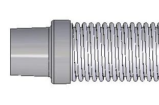
6. Connect Hose to the Cleaner’s Swivel Assembly
Connect the large hose cuff (Figure 13) of the leader hose to the swivel assembly on the cleaner head
(Figure 13). Push the cleaner into the pool and let it sink to the bottom (Figure 14).
Large hose cuff
of leader hose
designed to connect
to swivel assembly
(See “Hose Assembly”
on Page 3)
Figure 13
Figure 14
7. Turn the pool pump on
After completing the installation, turn the pool pump on and allow it to run for a couple of minutes to ensure
that all air cycles out of the system.
Great White Installation and User’s Guide8
Optional Installation
Vac Port Installation with Vacuum Regulator in Skimmer
If your pool has a vac port (Figure 15), you can install Great White using the Optional Installation.
Vac Port
Figure 15
1. Turn the pool pump off
2. Adjust valves for vacuuming
Adjust the pump valves (if your system has valves) to direct all suction to the dedicated vacuum line and the
skimmer. Close the main drain and all suction lines, except the line from the dedicated vacuum line to which
Great White will be connected, and the skimmer where the vacuum regulator will be installed.
3. Install vac port door fitting
WARNING! Suction entrapment, injury, and drowning hazard. If your pool has
a dedicated suction port (“vac port”) for vacuuming or for an automatic pool
cleaner, it must be covered when not in use.
A spring loaded safety cover (the “vac port fitting”) is included with this pool cleaner
Figure 16
(Figure 16). Install it on the dedicated vacuum line to prevent entrapment and injury. For
details please refer to the Vac Port Instruction sheet included with your vac port fitting.
To install the included vac port fitting:
1. Screw the vac port fitting into the dedicated vacuum line opening.
2. Orient the vac port fitting so the arrow on the door points up.
3. Secure the cover by tightening the allen-screw below the door, into the dedicated
vacuum line fitting.
4. Remove the skimmer basket from the skimmer
Great White Installation and User’s Guide9
Optional Installation (continued)
5. Install vacuum regulator
WARNING! Hazardous suction. Can cause entrapment with severe personal injury or drowning.
To install the vacuum regulator, insert the vacuum regulator and reducer cone in the skimmer (Figure 17).
Water Attach hose to
Level vac port
Vacuum
Regulator
with Regulator
Cap attached
Reducer
Cone
Skimmer
Gate valve for
vacuum port must
be fully open
1900 0405
Figure 17: Vacuum regulator and reducer cone inserted in skimmer
To prevent water from flowing through the top of the vacuum regulator, attach the regulator cap to the vacuum
regulator (Figure 18). Attach the end of the hose to the vac port fitting installed in the dedicated vacuum line
(Figure 17).
Skimmer
Regulator Cap
Vacuum
Regulator
Reducer Cone
To Pump
Figure 18: Vacuum regulator installed in the skimmer with the regulator cap attached
Great White Installation and User’s Guide10
Optional Installation (Continued)
6. Check Flow
With the main drain closed, and one end of the hose attached to the vac port fitting installed in the dedicated
vacuum line, insert the flow gauge into the other end of the hose. Keep the hose and flow gauge
underwater. Turn on the pump. With the pump running, adjust the vacuum regulator (in your skimmer) until
the indicator on the flow gauge is between minimum and maximum flow (Figure 19). Remove the flow
gauge and proceed to step 7.
Disc Indicator
Figure 19
7. Connect Hose to the Cleaner’s Swivel Assembly
Connect the large hose cuff (Figure 20) of the leader hose to the swivel assembly on the cleaner head.
Push the cleaner into the pool and let it sink to the bottom (Figure 21).
Large hose cuff
of leader hose
designed to connect
to swivel assembly
(See “Hose Assembly”
on Page 3)
Figure 20
Figure 21
8. Turn the pool pump on
After completing the installation, turn the pool pump on and allow it to run for a couple of minutes to ensure
that all air cycles out of the system.
Great White Installation and User’s Guide11
Section 3
Operation
This section contains information describing the movement and operation of your Great White Cleaner, as
well as tips for “fine-tuning” your pool’s valves and connections to optimize Great White’s cleaning ability.
Cleaner Operation and Movement
Clicking sound
This is the sound of the oscillator moving back and forth in the oscillator chamber. The best speed for it is
about 500 oscillations per minute. The vibration created by the oscillator moves the bristles and the cleaner.
If the oscillator is running too fast, the cleaner will have a tendency to climb up the pool wall past the
waterline, or “walk out of the pool” and suck air. Reduce the speed by adjusting the vacuum regulator in
the skimmer.
Movement around the pool
Random motion – The cleaner will visit most spots in the pool within a six (6) hour period. It is not
specifically programmed, and cannot see the dirt you are seeing. It is a random motion pattern.
The cleaner was designed to spend most of its time in the deep end, where most of the floor and wall area
exists. During a six (6) hour period, the cleaner will visit the shallow end a few times.
Rotating motion – The cleaner will rise up on one side and pivot a few times per minute. This is normal
and provides the following:
1. Allows leaves that are being pushed or dragged along to be sucked up into the vacuum chamber.
2. Allows the cleaner to:
Change direction
Get out of corners
Get away from ladders
Submerge below pool water level
Get off of domed main drain covers
Picks up “big stuff”
The cleaner will pick up some debris so large that it may jam. Simply stop the pump and remove the debris
from the oscillator, or the swivel assembly.
Great White Installation and User’s Guide12
Fine-tuning valves and connections
WARNING! Pool pump suction is hazardous and can cause entrapment with severe personal
injury or drowning. Use vacuum regulator (see instructions below) in pool cleaner system at all times.
NOTICE: Each pool’s hydraulic system and vacuum connections are different. Be sure you have installed
the vacuum regulator before you “fine-tune” the system. This not only regulates vacuum, but also acts as a
safety device.
WARNING! Suction entrapment, injury, and drowning hazard. If your pool has a dedicated suction
port (“vac port”) for vacuuming or for an automatic pool cleaner, it must be covered when not in use.
A spring loaded safety cover (the “Vac Port Fitting”) is included with this pool cleaner. Install it on the vac port to
prevent entrapment and injury. For details please refer to the Vac Port Fitting instruction sheet included with
your cleaner.
For the novice pool owner for whom pool vacuuming is a new experience, please read all of the following
points, installation instructions, and trouble shooting guide carefully.
Please note the following:
• “Vacuum” and “suction” are two words meaning the same thing.
• “Dedicated suction line”, “vac port”, and “vac fitting” are different terms for a hole in the side wall of
pool; this hole is connected to the pump suction and is dedicated to vacuuming.
• Some pools do not have a vac port. If your pool does have one, please read the “Suction Entrapment”
warning above.
For the seasoned pool owner: The automatic pool cleaner connection and vacuum adjustments can be
similar to using your manual pool vacuum. Please read on.
Valves (pump, skimmer, and main drain) and vacuum adjustments
You may need to spend some time adjusting the skimmer and main drain valves in order to obtain the best
vacuum setting for good cleaner operation. Once you have found the correct valve settings for best
operation, we suggest you mark the valves to ensure repeated success.
At first, set valves to give maximum vacuum to the skimmer or vac fitting you have elected to use.
Too much vacuum?
You have too much vacuum if the cleaner climbs up the pool wall past the water line to the point that the
cleaner sucks air and the pump loses prime. Frequent loss of prime will damage the pump. To correct this,
adjust the regulator by turning the adjustment knob counterclockwise. This will decrease the suction. If the
cleaner still climbs out and sucks air, open the main drain valve slightly.
Great White Installation and User’s Guide13
Fine-tuning valves and connections (continued)
Not enough vacuum?
You don’t have enough vacuum if the cleaner moves sluggishly or not at all. Be sure the filter system is clean
and the regulator and all valves are adjusted to give you maximum vacuum. If the cleaner is still not moving,
your pump may not be strong enough to operate the cleaner. Please refer to “Troubleshooting” on Page 17.
In-Line leaf canisters
If your pool is exposed to large quantities of leaves, we suggest purchasing and installing an in-line leaf
canister (part no. R211084K). A leaf canister will provide more debris-loading capacity and also provides a
water by-pass when the canister is full. It is very important that the pump not starve for water!
Skimmer connection
For pools that have large quantities of “big stuff” to pick up, we suggest using the bottom of the skimmer
connection in conjunction with an in-line leaf canister (part no. R211084K). A leaf canister will provide
more debris-loading capacity and also provides a water by-pass when the canister is full. It is very
important that the pump not starve for water!
Skimmer vac plates
Some pool owners connect the hose to a skimmer vac plate, which allows the skimmer basket to remain in
the skimmer. If this method is used, empty the basket frequently. Also make sure that the vacuum regulator
provided is completely submerged so that it will not suck air and damage the pump.
Skimmer vac plate vacuum control adjusters
Some pool owners use one of a variety of manufacturer’s skimmer vac plates. Some have a vacuum control
adjuster, and some do not. The adjuster could be a screw-type, a spring loaded apparatus, or a dial design.
For those vac plates with adjusters, it is important to adjust them when fine tuning the vacuum for the
cleaner.
Great White Installation and User’s Guide14
Blank Page
Great White Installation and User’s Guide15
Section 4
User Maintenance
This section describes the service and maintenance of the Great White cleaner.
WARNING! Hazardous suction. Stop pump before attempting to clean pool cleaner.
• Keep skimmer basket and pump strainer basket clean and free of debris.
• If cleaner jams with large debris (leaves, sticks, etc.), try cleaning debris first from bottom of unit. If
this doesn’t clear unit, remove top swivel assembly (turn 1/4 turn) and clear the debris from the top.
• Remove the pool cleaner from the pool before super chlorinating (shocking) or chemical balancing.
Wait at least four hours after the chemical procedure before reinstalling the cleaner.
• Make sure that the cleaner’s brush bristles don’t become deformed during storage. Store the unit so
that it doesn’t sit on the bristles and so that nothing compresses them.
• Do not coil the hose. Remove the hose from the cleaner when removing the cleaner from the pool.
Store the hose flat and straight.
• Periodically examine bristles and vacuum skirt for wear or distortion. Replace if necessary. See
"Reassembly", Page 15.
• Don't store the cleaner with the hose connected to the cleaner body or with the hose coiled. To do
so will cause the hose to take a set or kink over a period of time. When reinstalled in the pool, the
hose will tend to stay coiled and will cause the cleaner to malfunction.
• If the hose has taken a set, uncoil it as far as possible without damaging it and lay it out in the sun for
several hours to straighten itself. Once it has relaxed and straightened out, store it laid out flat and
straight (no coiling).
• Make sure the lift brush is retracted during storage. If the lift brush is down during storage and the
cleaner rests on it, the brush bristles will collapse over time and the cleaner will no longer turn during
operation as it was designed to do.
Hose Storage
Correct: Hose stored correctly – Wrong: Storing cleaner with hose
laid out straight, not connected to connected will damage hose and
cleaner. void the hose warranty.
Great White Installation and User’s Guide16
Disassembly
1. Remove swivel assembly (Figure 22) from the Swivel "Click" at
top of the cleaner by turning it 1/4-turn assembly this point
counterclockwise and pulling straight up on it.
2. Turn cleaner upside down. Remove 4 screws and
remove lower body assembly from shroud.
3 . Turn lower body assembly right side up. Unsnap
the 2 clips on the oscillator chamber cap (Figure
23a); lift it off. 3337 1098
4. Pull the long gear shaft straight up (Figure 23a) Locked Twist CCW Pull Straight
by the blocks on the ends of the shaft. Hold the 1/4 Turn Up
Figure 22
seals in the oscillator and the blocks on the shaft.
The cam may interfere with the shaft mounting Ocillator
post; if so, turn it slightly on the shaft until it Chamber
Cap
clears the post. The shaft assembly can now be Clip Block
disassembled (Figure 23b).
Long Gear Shaft Cam
5. Slide the long gear shaft out of the oscillator
(with gears, complete); make sure that you don’t Block
lose the seals out of the oscillator which may fall
out at this point (Figure 23b).
1889 0795
5A. Oscillator seals are replaceable. 1887 0795
5B. Ratchet gear set and long shaft are replaceable Figure 23a Figure 23b
as a unit.
6. Remove the set screw, short gear shaft, and
gears (Figure 24); be sure to keep the gears on.
7. With a small screwdriver (such as a jeweler’s
screwdriver), a pencil, or a pen point, depress
and remove the coil spring from the lift brush
mounting post (Figure 25). Replace the brush and
the spring if necessary.
8. The metal ratchet tab slides out of its slot
sideways; replace it by removing the center 1886 0795
brushes and sliding in a new ratchet tab until it is Figure 24 Figure 25
flush with the edge of plastic holder (Figures 26
and 27). Replace the center brushes. 1. Slide metal ratchet tab 2. Slide metal ratchet tab
toward end of cleaner body down through cleaner body
9. The brush ring pops out of the cleaner body for
easy replacement.
10. If you need to replace the bumper, turn the
shroud and bumper assembly upside down and
remove the two screws holding the bumper to the
shroud.
1885 0795
1884 0795
Figure 26 Figure 27
Great White Installation and User’s Guide17
Reassembly
1. Put both white seals in the oscillator; hold them in place.
2. Install the oscillator on the long gear shaft. Install the
ratchet gear on the shaft so that the teeth engage the
ratchet on the oscillator. Install the spring, ratchet drum,
pinion gear (large gear first), and cam (gear end first) on
the shaft (See Figure 28). Hold the gears on the shaft while
Seals
installing them, and compress the clutch spring to allow
assembly to slip into place between the posts (See Figure
28).
Figure 28
3. Install the long gear shaft and end blocks in the cleaning
head with the large arm of the cam down (see Figure 29). Make sure Oscillator 1894 0795
is partially inserted in
chamber while reinstalling
4. Reinstall the short gear shaft, set screw and two gears Shaft Assembly
(See Figure 30); the small pinion gears and the shaft set
screw go on the side toward the end of the cleaner – away
from the oscillator box. Make sure that the gears engage
the gears on the long gear shaft.
Swing Cam
5. Install the oscillator chamber cap and clip it in place. Arm up for
Clearance
6. Install the rubber vacuum skirt on the cleaner with the Oscillator
word ‘OUTSIDE’ showing. Start at the large pin on the Chamber
back of the cleaner head (see Figure 31) and work around
the cleaner. Make sure the skirt is flush against the stop Figure 29
strips on the cleaner head (see Figure 32). 1895 0795
7. Turn the cleaner over. If you removed the bumper and
brush ring, replace them now.
8. Install the lower body assembly in the shroud. Fasten the
cleaning head in place with 4 screws (2 long, 2 short – see
Figure 33).
NOTE: Make sure that you do not dislodge the rubber vac
skirt while inserting the lower body assembly past the brush
ring.
Not
This Figure 30 1890 0795
This
Figure 32 1892 0795
#10-16x1-3/4" Screws Lift Brush
Location
Center Center Start here with
large button when
Brush Brush installing vacuum skirt.
Location Location
'Outside' will show
(facing out) when OU
skirt is correctly installed. TS
IDE
Rubber
1891 0795 vacuum skirt
#10-16x1" Screws 1893 0795
Figure 33 Bottom View of Cleaner Figure 31
Great White Installation and User’s Guide18
Illustrated Parts List Optional Accessories
Vacpole
1
2
R
2A
1897 0405
3 Key
No. Description Part No.
4 1 Swivel Assembly GW9012
2 Bumper GW9502
5 2A Bumper Insert Kit (Set of 4) GW9520
3 3 Screw Kit (4 short, 2 long) GW9504
4 Shroud GW9501
5 Brush Ring GW9505
6 Oscillator Chamber Cap GW9506
7 Cam Kit (2 & 3 Leg Cams) GW9507
6
8 Idler Gear Kit (Incl. 3 Gears) GW9509
7 9 Block Kit (Incl. 2 Blocks) GW9512
10 Long Gear Shaft (Stainless Steel) GW9513
11 Set Screw #4 Self Tapping##
18 8
11A Shaft Kit, Stainless Steel (includes Set Screw) GW9536
9 12 Lower Body* GW9535
9 10 13 Lift Brush GW9517
11 14 Vacuum Skirt GW9508
11A 15 Lift Brush Spring GW9522
8 16 Ratchet Tab (Stainless Steel) GW9523
17 Oscillator Seal Kit (Incl. 2 Seals) GW9004
3 18 Oscillator Assembly Kit (Incl. Key #17)
12 (Ratchet Assembly not sold separately) GW9503
19 Center Brush Kit (Set of 2) GW9013
• Hose Kit, 12 sections, each 4 ft in length 41200-0131
• Vacuum Regulator 41200-0200
17
3 13 • Vacuum Regulator Cap 41200-0211
• Reducer Cone GW9015
• Unidapt Handle GW9019
3 16 • Vac Port Fitting GW9530
14 • Flow gauge 41200-0210
19
15
• Not Illustrated
1896 0795
* Includes Key Nos. 6, 11A, 13, 15, 16, two idler gears and 2-arm cam
## Not available separately
Great White Installation and User’s Guide19
Section 5
Troubleshooting
SITUATION SOLUTIONS:
Cleaner does not move 1. Backwash and/or clean filter. Empty all baskets. This should help your cleaner attain the desired
Oscillator is very slow oscillation rate of 400-600 times per minute.
2. Clear all debris from oscillator chamber, hose, or vac plate by-pass (if you have one).
3. Repair all sources of vacuum leaks (cracked vac plate, vac plate or reducer cone not seated
properly, cracked hose, vac regulator adjusted too loosely).
4. Adjust valves to give maximum vacuum to the vacuum port or skimmer to which you are attaching
the cleaner hose. Reduce or shut off other skimmers and main (floor) drain.
Note: Each pool’s hydraulic system is different. It may require some adjustments to skimmer and
main valves before you achieve the vacuum setting required for the best cleaner
operation. Once determined, mark the valves at that position to ensure repeated success.
5. Filtration system (pump) does not develop enough vacuum. Consult your pool service
professional.
6. In hot water, the hose may kink. The hose, when old, may have developed leaks (cracks or holes)
or may get brittle. Purchase a new hose.
NOTE: It must be a Great White hose for proper operation.
Cleaner climbs past water 1. Oscillator is running too fast. Make sure vacuum regulator is installed and adjusted.
line of pool causing pump to 2. If step 1 does not solve the problem, slightly open the main drain valve until the cleaner no
lose prime (suck air.) longer climbs out of the pool.
Cleaner coverage not as 1. A clean filter system will help the cleaner to move much faster. Also, be sure to clean all baskets.
expected 2. Vinyl liner pools with a deep end hopper will require 6-8 hours to clean. In this time the
cleaner should make at least 4 trips to the shallow end. If not, call Customer Service at 1-800-
831-7133.
3. Examine the lift brush mechanism as the cleaner is operating. To do this, you will have to turn
the cleaner over while it is running and submerged. If the lift brush does not move to the “down”
position within 2 minutes, call Customer Service at 1-800-831-7133.
4. The cleaner was not designed to work under solar covers. If you have a solar cover, only minimal
coverage can be expected.
5. Any cleaner might miss a spot. Your cleaner has been designed to accommodate the attachment
of a vac-pole (telepole) by use of the handle in the accessory bag. Attach pole for spot cleanups,
steps, and swimouts.
Cleaner “stuck” in one spot 1. Examine the lift brush mechanism as the cleaner is operating. To do this, you will have to turn the
(more than 15 mins.) cleaner over while it is running and submerged. If the lift brush does not move to the “down”
position within 2 minutes or less, call Customer Service at 1-800-831-7133.
Steps and “swim-outs” are 1. This cleaner was not designed to clean these areas. Use the handy telepole attachment,
not clean connect the pole, and clean missed areas.
Cleaner flips on its back 1. This is normal with some filter systems that develop a surge of back pressure when the system
when pump stops shuts off. The cleaner will right itself when the system is restarted.
Hose comes loose when 1. Use reducer cone when connecting to the skimmer or vac port.
pump stops
Cleaner hovers in one area 1. Hose might be too short. Desired length can be measured from the point where the hose is
with hose fully extended connected, to the furthest point of the pool, plus a minimum of an additional 4’. If needed, purchase
an extension hose from your local dealer. Do not cut extension hose – use it full length even if it is a
little long.
Hose keeps coiling up 1. For best results, when hose is not in use, store it uncoiled, flat, and straight.
2. Lay hose out flat and straight in the sunlight for a few hours prior to use.
Cleaner avoids 1. Bumper Inserts (see Key 2A, Page 18) help to make the cleaner more buoyant to allow better access
shallow end of pool to the shallow end of the pool. Do not install the bumper inserts from the top; they will become jammed
and not work properly. Install bumper inserts only from the bottom.
2. If the bumper on the cleaner appears to lift the cleaner to the surface of the pool, check for trapped air
in the cleaner and hose. If no air is found, remove one bumper insert block and watch and see if the
cleaner remains submerged and on the pool floor while working. If not, remove individual insert blocks
as needed until the cleaner rests on the pool floor and operates properly.
Great White Installation and User’s Guide20
Blank Page
Great White Installation and User’s GuideNettoyeur automatique de piscine
Guide d'installation et
d'utilisation
CONSIGNES DE SÉCURITÉ
LIRE ET SUIVRE ATTENTIVEMENT TOUTES LES CONSIGNES
VEUILLEZ CONSERVER CES CONSIGNESSoutien technique
Sanford, Caroline du Nord (8 h à 17 h)
Moorpark, Californie (8 h à 17 h)
Tél. : (800) 831-7133
Téléc. : (800) 284-4151
Sites Web : Visitez www.pentairpool.com et staritepool.com
Protégés par un ou plusieurs des brevets américains suivants et par tous les brevets internationaux
correspondants : brevet américain Nº 5,293,659, 5,303,444, 5,371,910, 5,386,607, 5,469,596,
5,664,275, 5,799,351 et 5,974,647
© 2007 Pentair Water Pool and Spa, Inc. Tous droits réservés.
Ce document est sujet à tous changements sans préavis.
1620 Hawkins Ave., Sanford, NC 27330 • (919) 566-8000
10951 West Los Angeles Ave., Moorpark, CA 93021 • (805) 553-5000
Marques de commerce et avis de non-responsabilité :
Great White® et Pentair Water Pool and Spa® sont des marques déposées de Pentair Water Pool and Spa, Inc. aux
États Unis et/ou dans d'autres pays. À moins qu'il en soit indiqué autrement dans ce document, l'utilisation des
noms et marques d'autres sociétés ne présuppose nullement l'affiliation entre les propriétaires de ces noms et
marques et la société Pentair Water Pool and Spa, Inc. ou leur endossement par cette dernière. Ces noms et
marques peuvent être des marques de commerce ou des marques déposées appartenant à ces parties ou à
d'autres.
PN789 (Rév. B) - 7 décembre 2007i
Table des matières
Consignes de sécurité importantes ............................................................................... ii
Section 1 : Survol .............................................................................................................. 1
Préparation de la piscine ......................................................................................... 2
Nettoyeur...................................................................................................... 2
Manches de raccordement .......................................................................... 3
Section 2: Installation ...................................................................................................... 5
Installation normalisée ............................................................................................. 5
Installation facultative ............................................................................................... 8
Section 3 : Fonctionnement 11
Fonctionnement et mouvement du nettoyeur .......................................................... 11
Bruit de cliquetis .......................................................................................... 11
Déplacement autour de la piscine ............................................................... 11
Aspiration de gros débris ......................................................................................... 11
Réglages précis des robinets et des branchements ............................................... 12
Robinets (pompe, écumoire et drain de fond) et réglages de l'aspiration .... 12
Trop d'aspiration? ........................................................................................ 12
Pas assez d'aspiration? .............................................................................. 12
Récupérateur de feuilles en ligne ................................................................. 13
Raccord de l'écumoire ................................................................................. 13
Plaque d'aspiration de l'écumoire ................................................................ 13
Dispositifs de réglage de l'aspiration de la plaque de l'écumoire ................. 13
Section 4 : Entretien 15
Remisage des tuyaux .............................................................................................. 15
Démontage .............................................................................................................. 16
Remontage .............................................................................................................. 17
Liste illustrée des pièces détachées........................................................................ 18
Section 5 : Dépannage ..................................................................................................... 19
Guide d'installation et d'utilisation du nettoyeur pour piscine Great Whiteii
CONSIGNES DE SECURITE IMPORTANTES
Notice importante :
À l'intention de l'installateur : Ce guide contient d'importantes informations sur l'installation, le fonctionnement
et des mesures de sécurité relatives à ce produit. Ces renseignements doivent être remis au propriétaire et/ou
à l'opérateur de cet équipement.
MISE EN GARDE — Avant d'installer ce produit, veuillez lire et suivre toutes les mises en garde et
consignes qui sont incluses. Le non-respect des mises en garde et des consignes
peut entraîner d'importantes blessures, la mort ou des dommages matériels.
Pour des copies supplémentaires gratuites de ce guide, veuillez appeler
le (800) 831-7133.
MISE EN GARDE — Aspiration dangereuse. Les cheveux ou des parties du corps risquent
d'être aspirés ou arrachés. Peut entraîner la noyade. Ne pas jouer avec le
nettoyeur ni avec son tuyau souple et ne pas se l'appliquer sur le corps.
Ne pas laisser les enfants utiliser le nettoyeur de piscine ni jouer avec.
Arrêter la pompe avant d'intervenir sur le nettoyeur.
ATTENTION — L'oscillateur peut causer des blessures aux mains ou aux doigts. Arrêter la
pompe avant de nettoyer la tête de ce nettoyeur de piscine.
1058 0594
MISE EN GARDE — Le tuyau souple peut faire trébucher les baigneurs ou s'enrouler autour
d'eux. Ne permettre à personne de se baigner dans la piscine pendant que le
nettoyeur fonctionne.
Information générale concernant l'installation
Liste des contrôles à effectuer avant de procéder à l'installation
Avant d'installer ce nettoyeur dans une piscine avec une toile en vinyle :
Vérifier attentivement si la toile ne comporte pas des signes de détérioration ou de dommages causés par le
vieillissement ou les produits chimiques. Si on remarque des dommages, demander à un professionnel qualifié
en piscines de procéder aux réparations nécessaires. De même, si on remarque la présence de pierres, de
racines, etc. sous la toile, les enlever avant d'installer le nettoyeur.
Avant de procéder à l'installation du nettoyeur dans une piscine en béton projeté (gunite) ou dans
une piscine partiellement ou complètement carrelée :
Réparer tous les carreaux qui se détachent et resserrer les bagues desserrées de tous les éclairages.
Guide d'installation et d'utilisation du nettoyeur pour piscine Great Whiteiii
CONSIGNES DE SECURITE IMPORTANTES (suite)
Informations générales concernant l'installation (suite)
Avant d'installer ce nettoyeur, nettoyer le système de filtration:
Ne pas oublier de nettoyer le filtre, de le laver à contre-courant, de le rincer et de vider tous les paniers. Il est
indispensable que le système soit propre pour que le nettoyeur puisse fonctionner correctement et sur toute la
surface de la piscine.
Remplir d'eau le tuyau avant d'installer le nettoyeur :
AToujours s'assurer que la tête du nettoyeur est immergée dans l'eau de la piscine et que son tuyau est rempli
d'eau avant de le brancher sur le système de filtration (dans le retour de l'écumoire ou dans un retour de la paroi
de la piscine réservé à cet effet). S'il y a de l'air dans le système, la pompe fonctionnera à sec, surchauffera et
sera endommagée.
Avant d'installer ce nettoyeur, il faut bien comprendre comment il fonctionne :
Ce nettoyeur est conçu pour nettoyer une piscine sur une période d'environ 4 à 6 heures. Dans la plupart des
cas, il faudra beaucoup moins de temps.
Ce nettoyeur automatique n'a pas été conçu pour nettoyer les marches ou les rampes, ni pour fonctionner sous
une couverture solaire. Il n'a pas non plus été conçu pour procéder au nettoyage initial d'une piscine neuve, ni
pour nettoyer une piscine lorsqu'on la rouvre pour la saison.
MISE EN GARDE — Risque d'aspiration, de blessures ou de noyade. Si la piscine comporte un
orifice spécifique pour le nettoyage à l'aspirateur, cet orifice devra être
bouché s'il n'est pas utilisé.
Un couvercle de sécurité à ressort (raccord d’orifice de nettoyage à l’aspirateur) est livré avec votre nettoyeur.
Installez-le sur l’orifice d’aspiration pour empêcher que les baigneurs soient retenus ou blessés.
Guide d'installation et d'utilisation du nettoyeur pour piscine Great Whiteiv
Page vierge
Guide d'installation et d'utilisation du nettoyeur pour piscine Great White1
Section 1
Survol
Nettoyeur automatique de piscine Great White
Félicitation vous avez acheté le meilleur nettoyeur de piscine!. Aucun autre nettoyeur ne se compare à la
puissance de nettoyage du Great White. Doté d'une conduite de 15 pieds et d'un entraînement à brosse, le
nettoyeur pour piscine creusée automatique Great White nettoie complètement et rapidement toute la
piscine.
Nettoyeur automatique de piscine creusée Great White, modèle GW9500
Guide d'installation et d'utilisation du nettoyeur pour piscine Great White2
Préparation de la piscine
Avant d'assembler et d'installer le nettoyeur automatique de piscine Great White, vous assurez que la piscine
et propre et exempte d'algues. Effectuer les préparations suivantes avant de procéder à l'installation, si
nécessaire. Panier
d’écumoire
• Équilibrer la chimie de l'eau de la piscine.
• Passer la brosse sur le vinyle et laisser
les débris se déposer dans le fond. Crépine
de la pompe
• Nettoyer complètement la piscine
à l'aide de l'aspirateur manuel.
• Nettoyer le filtre et le panier de l'écumoire (Figure 1)
Figure 1
Nettoyeur
1. Vérifier les pièces
Retirer et vérifier le nettoyeur Great White et toutes les pièces de la boîte afin de s'assurer que toutes les
composantes soient présentes (Figure 2).
• Nettoyeur
Nettoyeur
• Embout oscillant
• Adaptateur de manche Adaptateur de manche
• Cône de réduction Embout Cône
oscillant de réduction
• Tuyau : Douze tuyaux de
4 pieds
W
O
M FL
OW
MAXIMU
M FL
MINIMU
• Régulateur d'aspiration Douze
tuyaux Débitmètre
• Couvercle du régulateur de 4 pieds
• Raccord d'orifice Raccord Régulateur Couvercle
d'aspiration d’orifice d’aspiration du régulateur
d’aspiration
• Débitmètre
Figure 2
2. Fixation de l'embout oscillant à la tête du nettoyeur
L'embout oscillant se pose facilement. L'introduire dans le corps du nettoyeur et le tourner d'un quart de
tour (Figure 3). Si, pour le nettoyage manuel, on fixe un manche Unidapt sur l'embout oscillant, s'assurer
qu'il est du type spécial et flottant, comme celui livré avec le nettoyeur (pièce de remplacement nº
GW9019). L'utilisation de tout autre manche Unidapt ne permettra pas un nettoyage adéquat.
Embout
oscillant
Figure 3
Guide d'installation et d'utilisation du nettoyeur pour piscine Great White3
Tuyaux
Assembler le tuyau
Le nettoyeur est livré avec douze sections de tuyau, chacune mesurant 4 pieds de longueur (Figure 4). Ces
tuyaux ne doivent pas être coupés. Ces sections de 4 pieds doivent être reliées pour créer une longueur
de tuyaux qui aura au moins 4 pieds de plus que la longueur à
brancher entre la source d'aspiration (l'écumoire ou la conduite
d'aspiration réservée à cet effet) et le point le plus éloigné de la piscine Douze
(Figure 5). Joindre les sections de tuyau entre elles en raccordant tuyaux de 4 pieds
l'extrémité mâle à l'extrémité femelle (Figure 6). La section de tuyau
" principale " est dotée d'un embout repéré qui est plus grand
que celui des autres sections afin de se brancher sur l'embout
Figure 4
oscillant du nettoyeur (Figure 7 et 8). Utilisation de tout autre
tuyau diminuera les performances du nettoyeur. Si d'autres tuyaux sont
requis, n'utiliser que des tuyaux provenant d'un marchand Pentair Water Pool and Spa (nº de pièces de
remplacement 41200-0131). L'Utilisation de tout autre tuyau diminuera les performances du nettoyeur.
Le tuy
au doi
t atteind
re le p
o int le p
lus élo
igné —
— plus a
u
1,22 m moins
ètre (
4 pied
s)
Figure 5
Extrémité femelle Extrémité mâle du
du tuyau tuyau
Tuyau principal
Embout
oscillant
Figure 6
Branchement du tuyau
principal sur l'embout oscillant
Figure 8
Figure 7
Guide d'installation et d'utilisation du nettoyeur pour piscine Great White4
Page vierge
Guide d'installation et d'utilisation du nettoyeur pour piscine Great White5
Section 2
Installation
Cette section explique comment procéder à l'installation du nettoyeur automatique de piscine Great White. Le
nettoyeur de piscine Great White est conçu pour fonctionner avec un grand nombre de piscines. Les deux
méthodes d'installation, dans l'écumoire et par raccord d'orifice d'aspiration sont décrites ci dessous. Si vous ne
retrouvez pas la configuration de votre piscine dans les exemples mentionnés, contactez un représentant de
produits Pentair Water Pool and Spa ou appeler le Service à la clientèle en composant le numéro sans frais 1-
800-831-7133.
Installation normalisée
Piscines dotées d'une seule écumoire, utilisant le régulateur d'aspiration
Le fabricant recommande de procéder à l'installation standard par l'écumoire de la piscine (Figure
8). L'avantage de cette installation est l'utilisation du régulateur d'aspiration (Figure 9) pour
équilibrer le débit de l'eau entre l'écumoire et le nettoyeur de piscine Great White. Le régulateur
d'aspiration peut être ajusté aux modifications du débit d'eau afin de fournir au nettoyeur Great
White la puissance nécessaire pour faire un nettoyage adéquat; il est recommandé par le fabricant
afin d'augmenter la sécurité et la performance du nettoyeur.
Écumoire Régulateur
d’aspiration
Bouton
de réglage
Figure 8 Figure 9
1. Arrêter la pompe de la piscine.
2. Régler les robinets pour procéder à l'aspiration
Régler les robinets de la pompe (si votre système est doté de robinets) pour y diriger toute l'aspiration.
Fermez le drain principal et toutes les conduites d'aspiration, sauf la conduite de l'écumoire à laquelle le
nettoyeur Great White sera branché.
3. Retirer le panier de l'écumoire
4. Installer le régulateur d'aspiration
MISE EN GARDE! Aspiration dangereuse. Risque de se faire retenir, d'être gravement blessé ou
de se noyer.
Toujours utiliser le régulateur d’aspiration avec le nettoyeur automatique de piscine. Le régulateur
d’aspiration com-porte un bouton de réglage (Figure 9). Si l’aspiration est trop forte, tourner le bouton dans
le sens antihoraire afin de réduire l’aspiration. Si l’aspiration est trop faible, tourner le bouton dans le sens
horaire afin d’augmenter l’aspiration.
Guide d'installation et d'utilisation du nettoyeur pour piscine Great White6
Installation normalisée (suite)
Le régulateur d'aspiration doit être installé en conjonction avec le cône de réduction (Figure 10). Le cône
de réduction est indispensable pour réaliser la plupart des connections avec l'écumoire. Il permet de
maintenir le tuyau et le régulateur d'aspiration en place lorsque le système de filtration est arrêté.
Figure 10
Installer le régulateur d'aspiration et le cône de réduction dans l'écumoire. Fixer l'embout du tuyau dans le
régulateur (Figure 11).
Écumoire
Régulateur
d’aspiration
Cône de réduction
Vers pompe
Figure 11: Régulateur d'aspiration installé dans l'écumoire avec le tuyau fixé
S'assurer que le régulateur d'aspiration est submergé en tout temps. Sinon, la pompe aspirera de l'air et se
désamorcera, ce qui risque de l'endommager.
Guide d'installation et d'utilisation du nettoyeur pour piscine Great White7
Installation normalisée (suite)
5. Vérification du débit
Fermer le drain principal et introduire une extrémité du tuyau dans le régulateur d'aspiration situé dans
l'écumoire, puis insérer le débitmètre dans l'autre extrémité du tuyau. Maintenir le tuyau et le débitmètre sous
l'eau. Démarrer la pompe. Pendant que la pompe fonctionne, régler le régulateur d'aspiration (situé dans
l'écumoire) jusqu'à ce que l'indicateur du débitmètre soit réglé entre les débits minimal et maximal (Figure
12). Retirer le débitmètre et procéder à l'étape 6.
Indicateur circulaire
Figure 12
6. Branchement du tuyau sur l'embout oscillant du nettoyeur
Brancher l'embout repéré du tuyau principal sur l'embout oscillant du nettoyeur (Figure 13). Laisser tomber
le nettoyeur au fond de la piscine (Figure 14).
La longue section
de tuyau principale
est dotée d'un manchon
de tuyau qui est plus grand
que celui des autres sections
afin de se brancher sur l'embout
oscillant du nettoyeur
(voir la section Tuyau à la page 3)
Figure 13
Figure 14
7. Démarrer la pompe.
Après avoir complété l'installation, démarrer la pompe de la piscine et la laisser fonctionner quelques
minutes afin que l'air soit complètement évacué du système.
Guide d'installation et d'utilisation du nettoyeur pour piscine Great WhiteVous pouvez aussi lire