INTELLIBRITE 5G WHITE POOL AND SPA LIGHTS - INSTALLATION AND USER'S GUIDE
←
→
Transcription du contenu de la page
Si votre navigateur ne rend pas la page correctement, lisez s'il vous plaît le contenu de la page ci-dessous

INTELLIBRITE 5G
                    ®

WHITE POOL AND SPA LIGHTS

                            INSTALLATION AND
                                USER’S GUIDE

    IMPORTANT SAFET Y INSTRUCTIONS
     READ AND FOLLOW ALL INSTRUCTIONS
         SAVE THESE INSTRUCTIONS
           INTELLIBRITE® 5G White Pool and Spa LED Light Installation and User’s Guide
Technical Support: Phone: (800) 831-7133 - Fax: (800) 284-4151
Web sites: www.pentairpool.com and www.staritepool.com:
                                                    Contents
   IMPORTANT WARNING AND SAFETY INSTRUCTIONS...................................i
   IntelliBrite Underwater White Pool and Spa Light ............................................ 1
   Operating IntelliBrite lights using a wall switch .................................................. 1
   Using an External Transformer for Multiple IntelliBrite 12 VAC Lights .................
   Troubleshooting ................................................................................................2
   Replacing the IntelliBrite White Pool and Spa Light Assembly
   (in an existing pool) ........................................................................................... 3
   Installing the IntelliBrite White Pool and Spa Light Fixture
   (new pool construction) ..................................................................................... 6
   Installing the IntelliBrite White Pool and Spa Light Fixture
   (after electrical requirements are met)................................................................7
   Replacing the IntelliBrite White Pool Light Circuit Board Assembly
   (in an existing pool)............................................................................................ 9
   Replacing the IntelliBrite White Pool Light Circuit Board Assembly
   With New Gasket ............................................................................................. 11
   Wide and Narrow Angle Lens Adjustment........................... ......................... ...15
   IntelliBrite White Pool Light Replacement Kit Part Numbers ...........................16
   Replacing the IntelliBrite White Spa Light Face ring and Gasket
   (P/N 640045) or Gasket and Lens (640046) ................................................... 17
   IntelliBrite White Spa Light Replacement Kit Part Numbers ........................... 21

    Before Installing luminaries read the following:
			                Always install a new lens gasket (see part number in this
 		                User’s Guide on page 12 and 22), when ever reassembling
 the light. Failure to do so may permit water to leak into the assembly which
 could cause; (a) an electrical hazard resulting in death or serious injury to pool
 users, installer, or others due to electrical shock, or (b) breakage of the lamp
 or lens, which likewise could result in serious injury to pool user, installers, or
 bystanders, or in damage to property.
     FOR 12 VAC LUMINARIES: ALWAYS USE A SEPARATE STEP DOWN
     TRANSFORMER TO POWER LUMINARIES. SEE DIAGRAM ON PAGE 23.
     Note: Connect all three wires to the corresponding circuit wires in the Junction
     Box (black wire to power, white wire to common, and green wire to ground). 12
     VAC LUMINARIES SPECIFICATION: 12 VAC, 50/60 Hz
     REPLACE ANY CRACKED PROTECTIVE SHIELD (CRACKED LENS) WITH
     NEWLENSAND GASKET.

              THE INTELLIBRITE 5G LED POOL LIGHT AND SPA
   LIGHT CANNOT BE USED ON A DIMMER CIRCUIT. USING A
   DIMMER SWITCH WILL RESULT IN PERMANENT DAMAGE TO
   THE LIGHT.
  P/N 619921 Rev H - 10/2014
INTELLIBRITE® 5G White Pool and Spa Lights Installation and User’s Guide
i

      IMPORTANT WARNING AND SAFETY INSTRUCTIONS
                   SERIOUS BODILY INJURY OR DEATH CAN RESULT IF THIS LIGHT
                   IS NOT INSTALLED AND USED CORRECTLY.
                    INSTALLERS, POOL OPERATORS AND POOL OWNERS MUST
                    READ THESE WARNINGS AND ALL INSTRUCTIONS BEFORE
                    USING THE POOL AND/OR SPA LIGHT.
                    Most states and local codes regulate the construction, installation,
		                  and operation of public pools and spas, and the construction of
residential pools and spas. It is important to comply with these codes, many of which
directly regulate the installation and use of this product. Consult your local building and
health codes for more information.
              IMPORTANT NOTICE - Attention Installer: This Installation and User’s
              Guide (“Guide”) contains important information about the installation, operation
              and safe use of this underwater pool and spa light. This Guide should be given
              to the owner and/or operator of this equipment.
                   Before installing this product, read and follow all warning notices
		                 and instructions in this Guide. Failure to follow warnings and
instructions can result in severe injury, death, or property damage.
Call (800) 831-7133 for additional free copies of these instructions. Please refer to www.
pentairpool.com for more information related to this products.
                   Risk of electrical shock or electrocution:
                   THE IntelliBrite® White Pool and Spa light require high voltage
                   which can shock, burn, or cause death.
                   BEFORE WORKING ON POOL AND SPA LIGHTS always disconnect power
                   to the pool and/or spa lights at the circuit breaker from the light
                   before servicing the light. Failure to do so could result in death
                   or serious injury to service person, pool users or others due to
                   electric shock.
This underwater light must be installed by a licensed or certified electrician or a
qualified pool professional in accordance with the current National Electrical Code
(NEC), NFPA 70 or the Canadian Electrical Code (CEC), CSA C22.1. All applicable
local installation codes and ordinances must also be adhered to. Improper installation
will create an electrical hazard which could result in death or serious injury to pool
users, installers or others due to electrical shock, and may also cause damage
to property. Always disconnect the power to the pool light at the circuit breaker
before servicing the light. Failure to do so could result in death or serious injury to
serviceman, pool users or others due to electrical shock.
                  Important Safety Information for Pentair Aquatic Systems Niche
                  and Light Installation
      •    All Niche and Light installations must conform with all codes. If local codes
           mandate a cord seal, use Pentair Aquatic Systems plastic niches
           (P/N 79206600 and P/N 79206700) and Cord Seal Kit (P/N 670044).
      •    Under no circumstances replace lights by splicing wire under water or behind
           niche.

                READ AND FOLLOW ALL INSTRUCTIONS IN THIS MANUAL.

                       INTELLIBRITE® 5G White Pool and Spa Lights Installation and User’s Guide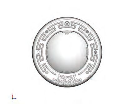
ii

      IMPORTANT WARNING AND SAFETY INSTRUCTIONS
                  RISK OF ELECTRIC SHOCK AND INJURY. USE ONLY THE
                  INSTALLATION METHOD SPECIFIED BELOW.
 Location of   Pentair Water Pool and Spa Fountain     Required Installation Method
 Luminaire Use Fixture* (P/N 560001 and P/N 560000)
 Swimming Pool Wet-Niche Swimming Pool		               Fixture Housing (Forming Shell) ONLY.
 and Spa 		    (or Spa) Luminaire (Light)		            DO NOT USE Fountain Fixture Stand.

 Fountain		    Wet-Niche Submersible Luminaire (Light) Fixture Housing (Forming Shell) or
 		            swimming Pool (or Spa) Luminair (Light) Fountain Fixture Stand

(*) Note: Wet-niche luminaires complying with requirements for both uses may bare
both the Listed Wet-Niche Submersible Luminaires UL Mark. A luminaire not bearing the
corresponding UL Listing Mark is not considered by UL to have been produced under UL’s
Listing and Follow-Up Service for the associated usage location.
CAUTION - The IntelliBrite® White Light fixture must only be used with Pentair Aquatic
Systems fixture housings (niches). If the IntelliBrite white light fixture is installed into other
niches, the installation will not carry U.L. approval and will void all warranties.
NOTICE: The external flexible cable or cord of this luminaire cannot be replaced; if
the cord is damaged, the luminaire shall be destroyed.
                     For countries in compliance with International Electromechnical
		                   Commission (IEC) regulatory standards: The light fixture must
be installed by a licensed or certified electrician or a qualified pool service person, in
accordance with IEC 364-7-702 and all applicable local codes and ordinance. Improper
installation will create an electrical hazard, which could result in death or serious injury
to pool user, installer or other due to electrical shock and may also cause damage to the
property.
		                   Salt is an inherently corrosive material. While the levels of salt required
		                   for proper operation of an electronic chlorine generator are relatively low
when compared to sea water and other salt solutions, placing any amount of salt in your
pool increases the likelihood of corrosion or other deterioration of pool equipment and any
surfaces used in and around your pool. Metal parts and certain natural and man-made
surfaces are particularly susceptible to corrosion and deterioration when used in and
around salt water pools. Pentair does not represent or otherwise guarantee that the proper
use of an electronic chlorine generator will prevent corrosion or other deterioration of pool
equipment and any surfaces used in and around your pool. Consult your experienced
pool professional, who should be able to advise you on the proper material selection,
installation techniques for those materials, and the proper use, care and maintenance of
those materials for your specific pool type and location in order to minimize the corrosion
and deterioration that is inherent in and around salt water pools.
POOL AND SPA FIXED LUMINARIES: Follow these guidelines when installing,
replacing or reparing Pentair Aquatic Systems Pool and Spa fixed luminaries:
- REPLACE ANY CRACKED PROTECTIVE SHIELD (CRACKED LENS) WITH NEW
LENS AND GASKET. FOR MORE INFORMATION SEE PAGE 11.
- FOR LIGHT OPERATION, ONLY USE A SAFETY ISOLATION TRANSFORMER.
CAUTION! Luminaires not suitable for direct mounting
on normally flammable surfaces (suitable ONLY for
mounting on non-combustible surfaces.
Fixed pool and spa luminaries specification:
12 VAC 50/60 Hz - 120VAC        ,50/60 Hz.
INTELLIBRITE® 5G White Pool and Spa Lights Installation and User’s Guide
                                                                               Surface Mount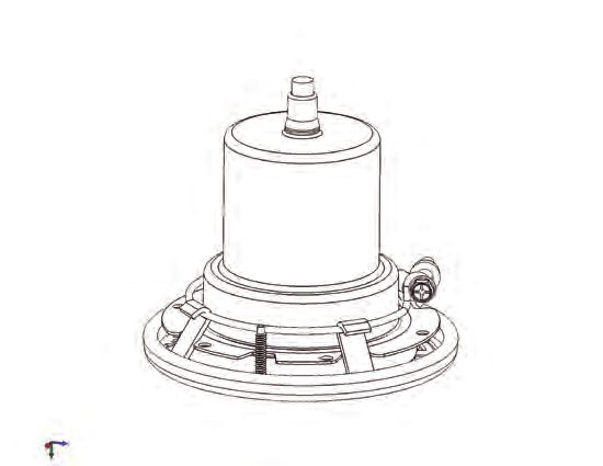
1
              ®
IntelliBrite 5g White Pool and Spa Lights Overview
This manual describes how to install the IntelliBrite 5g white underwater pool light and the
white spa light. The IntelliBrite white lights provides brilliant white light for a spectacular
effect in your pool and spa. The unique IntelliBrite 5g white pool light lens geometry (pool
light only) provides a choice between two light beam shapes; wider coverage with less
intensity, or narrower coverage with more intensity. For more information, see page 14.

Operating Pool and Spa Lights Using a Wall Switch (12 VAC)
The white pool and spa lights can be manually controlled using a standard wall-mount
light switch. Multiple IntelliBrite lights can be connected via a junction box to a single
switch so that all lights can be switched on and off together. IntelliBrite lights can also
be automatically controlled via Pentair IntelliTouch®, EasyTouch® and SunTouch® Control
Systems. For more information refer to the IntelliTouch User’s Guide (P/N 521075),
EasyTouch User’s Guide (P/N 521044), and SunTouch User’s Guide (P/N 520785).

Using an External Transformer for Multiple IntelliBrite 12 VAC Lights
When using multiple IntelliBrite 12 VAC lights on a 300 Watt transformer, it is
recommended that no more than three IntelliBrite pool lights and one (1) IntelliBrite Spa
light be used. It is also recommended not to exceed 100 feet of total cable run between
the transformer and light. Note: For long cable lengths, set transformer to 14 VAC (see
diagram below).

      300 Watt           12 Gauge
                                         J Box
    Transformer         (minimum)

                                                       100 ft.

                                    150 ft. max. for spa light

      300 Watt           12 Gauge        J Box
    Transformer         (minimum)

                                     200 ft. max. for pool light

                       INTELLIBRITE® 5G White Pool and Spa Lights Installation and User’s Guide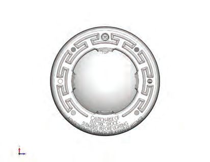
2

IntelliBrite® 5g White Pool Light models:
There are two IntelliBrite 5g White Pool light models:
     •    IntelliBrite 5g White Pool Light, 120 VAC with integrated
          12 VAC transformer, 50 ft. cord length - Other cord lengths are available
          from 30 ft. (9.14 m) to 250 ft. (76.2 m).
     •    IntelliBrite 5g White Pool Light, 12 VAC requires 120 VAC to 12 VAC
          transformer), 50 ft. cord length - Other cord lengths are available from 30
          ft. (9.14 m) to 150 ft. (45.72 m).

IntelliBrite White Spa Light models
There are two IntelliBrite White Spa light models:
    •   IntelliBrite White Spa Light, 120 VAC, with integrated 12 VAC transformer,
        50 ft. cord length - Other cord lengths are available from 30 ft. (9.14 m) to
        250 ft. (76.2 m).
    •   IntelliBrite White Spa  Light, 12 VAC, (requires 120 VAC to 12 VAC
        transformer), 50 ft. cord length - Other cord lengths are available from 30
        ft. (9.14 m) to 150 ft. (45.72 m).

Note: For IntelliBrite 5g white pool and spa white light replacement parts list,
see page 15-16 and 21-22.

Troubleshooting
Problem				Cause/Action
The light will not illuminate.		 Check the GFCI ground fault wiring and reset if
				necessary.

Light does not function properly. Check the light wiring connection to the junction box
				                              at the pool side and to the AC power switch.

				                              Be sure that there is proper AC power applied to
				the light.

INTELLIBRITE® 5G White Pool and Spa Lights Installation and User’s Guide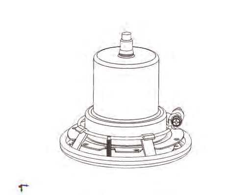
3

Replacing the IntelliBrite® 5g White Pool and Spa
                Light Assembly
          (in an existing pool or spa)
             Risk of Electrical Shock or Electrocution!
              This underwater light must be installed by a licensed or certified
              electrician or a qualified pool professional in accordance with
              the National Electrical Code and all applicable local codes and
              ordinances. Improper installation will create an electrical hazard
              which could result in death or serious injury to pool users,
              installers or others due to electrical shock, and may also cause
              damage to property.

              Always disconnect the power to the pool light at the circuit
              breaker before servicing the light. Failure to do so could result in
              death or serious injury to serviceman, pool users or others due
              to electrical shock.

Verify that the pool and spa meets the requirements of the current National Electrical
     Code and all local codes and ordinances. A licensed or certified electrician must
     install the electrical system to meet or exceed those requirements before the
     underwater light is installed. Some of the requirements of the National Electrical
     Code which the pool’s electrical system must meet are as follows:
     •    The lighting circuit has a Ground Fault Circuit Interrupter (GFCI) for line
          voltage models, and has an appropriately rated circuit breaker.
     •    The Junction Box (or, for 12 volt models, the low voltage transformer) is
          located at least eight (8) inches (20.3 cm) above ground level and at least 48
          inches (1.219 m) from the edge of the pool; see Figure 1 on page 7.
     •    The light fixture and all metal items within five (5) feet (1.524 m) of the pool
          are properly electrically bonded.
     •    The wet niche is properly installed so that the top edge of the underwater
          light’s lens is at least 18 inches below the surface of the water in the pool;
          see Figure 1 on page 7.
     •    The wet niche is properly electrically bonded and grounded via the No. 8
          AWG ground connector located at the rear of the niche; see Figure 1 on
          page 7.

    Note: The pool and spa electrical system can be verified with a Pool
    and Spa Electrical Qualification Test Kit. The electrical system inspector
    using this kit must be performed by trained and certified personnel.
    •. To be certain that the pool’s electrical system meets all applicable
        requirements, the electrician should also consult the local building
        department.
    •   Use only Pentair wet niches to insure proper bonding and
        grounding connections.

                  INTELLIBRITE® 5G White Pool and Spa Lights Installation and User’s Guide
4

     Replacing the IntelliBrite® 5g White Pool and Spa
                      Light Assembly
         (After Electrical Requirements Are Met)
The following removal and installation instructions describe how to remove
and install the IntelliBrite pool and spa white light assembly. Also use these
instructions after completing the following light replacement procedure:
    •    IntelliBrite White Spa Light and Face Ring Gasket
         and Lens Removal and Installation instructions, on
         page 17.

     Failure to bring the pool or spa’s electrical system up to code requirements
     before installing the underwater light will create an electrical hazard which
     could result in death or serious injury to pool users, installers, or others due to
     electrical shock, and may also cause damage to property.

    1.   WARNING! Switch off main electrical switch or circuit breaker, and the
         switch which operates the IntelliBrite underwater light.
    2.   To remove light fixture assembly from the pool. Remove the special
         bronze pilot screw at top of face ring. Remove the IntelliBrite light assembly
         from the niche and place it on the deck.
    3. Cut the cord about 12 inches (30.5 cm) from the back of the light
       assembly.
    4. Remove Junction Box cover, disconnect the light fixture wires, and
       pull the cord through the conduit. Tip: Before pulling the cord, tape
       the new cord to the existing cord, This might make it easier to
       feed the new cord through the conduit (see following step).
    5. Feed the new light fixture cord through the conduit from the niche
       to the Junction Box. Note: Depending on the length of the conduit,
       special tools may be required to pull the cord through the conduit.
    6. Leave at least four (4) feet of cord to coil around the light fixture;
       see Figure 1 on page 7. This four (4) feet (1.2192 m) of cord coiled
       around the light allows the light to be serviced after the pool is filled
       with water.
    7. Cut the cord at the Junction Box, leaving at least size (6) inches of
       cord to make connections.
    8. Strip six (6) inches (15.2 cm) of the outer cord jacket from the cord
       to expose the three insulated conductors. Be careful not to damage
       the insulation on the three (3) inner conductors). Strip a 1/2” of insulation

INTELLIBRITE® 5G White Pool and Spa Lights Installation and User’s Guide
5
9. Connect the three light wires (or two wires) to the corresponding light
circuit wires in the Junction Box. For three wires; connect the black
wire to power, white wire to common, and the green wire to ground.
10. For two wires connect the corresponding circuit wires (match the wire
colors) in the Junction Box. Secure the Junction Box cover.
11. Install the IntelliBrite® light assembly into the pool niche. Be sure to
insert the TAB on the lower part of the face ring into the niche SLOT
(located on the lower part of the niche). This is important to secure
the lower part of the light assembly onto the niche before tightening
the pilot screw.
12. Carefully tighten the special bronze pilot screw to secure the upper
part of the light assembly onto the niche.
Use only the special pilot screw provided with this
underwater light. This screw mounts and electrically grounds the housing
securely to the mounting ring and wet niche. Failure to use the screw
provided could create an electrical hazard which could result in death or
serious injury to pool users, installers or others due to electrical shock.
Pilot screw (bronze) Pilot screw (bronze)
Face ring TAB
(insert into
niche slot)
IntelliBrite 5g White Pool Light IntelliBrite 5g White Spa Light
13. Final check for proper IntelliBrite light operation: Switch on
the main switch or circuit breaker to the system, and the switch
that operates the IntelliBrite underwater light itself. The light should
illuminate when power is applied. If not recheck the installation steps
starting with Step 1 (page 4).
INTELLIBRITE® 5G White Pool and Spa Lights Installation and User’s Guide6
IntelliBrite® 5g WHITE Pool AND SPA light FIXTURE
INSTALLATION (new pool construction)
The following describes how to install the IntelliBrite® White Pool Light fixture
and the IntelliBrite® White Spa Light fixture. Read page 3 before starting the
installation procedure.
BEFORE STARTING: The following steps 1-7 (page 7-8) describe the tasks
that must be completed by the electrician before the IntelliBrite light fixture
is installed. See Figure 1 diagram on page 7.
Be sure that the pool or spa meets the requirements of the current National
Electrical Code (N.E.C.) Article 680-22 and all local codes and ordinances.
A licensed or certified electrician must install the electrical system to meet or
exceed those requirements before the underwater light is installed. Some of
the requirements of the National Electrical Code which the pool’s electrical
system must meet are as follows:
• The lighting circuit has a Ground Fault Circuit Interrupter (GFCI) for line
voltage models, and has an appropriately rated circuit breaker.
• The Junction Box (or, for 12 volt models, the low voltage transformer) is
located at least eight (8) inches (20.3 cm) above ground level and at least
48 inches (1.219 m) from the edge of the pool; see Figure 1 on page 7.
• The light fixture and all metal items within five (5) feet (1.524 m) of the
pool are properly electrically bonded.
• The wet niche is properly installed so that the top edge of the underwater
light’s lens is at least 18 inches below the surface of the water in the pool;
see Figure 1 on page 7.
• The wet niche is properly electrically bonded and grounded via the
No. 8 AWG ground connector located at the rear of the niche; see
Figure 1 on page 7.
Note: To be certain that the pool or spa electrical system meets all
applicable requirements, the electrician should also consult the local
building department. Use only Pentair wet niches to insure proper bonding
and grounding connections.
INTELLIBRITE® 5G White Pool and Spa Lights Installation and User’s Guide7
Installing the IntelliBrite® 5G WHITE POOL AND SPA light
Fixture (after electrical requirements are met)
ite White light (after electrical requirements are met)
To install the IntelliBrite® White Pool Light and Spa Light fixture:
1. Route light cable through conduit to Junction Box, leaving at least four (4)
feet of cable at the light fixture to coil around the light (this allows the light to
be serviced after the pool is filled with water). See Figure 1 below.
48"
min.
To GFCI, Circuit
Breaker and 4" min. 8" min. Junction Box or
Power Source. low Voltage Transformer.
Rigid 18" min. to top of Lens.
Conduit
#8 AWG Ground Pilot screw @12 o'clock position
Connector bonding
is located at rear Concrete must be cut
of Niche. back around Niche to
allow for a compacted
plaster seal.
11.50"
Coil 4 ft. of light
cable around fixture.
16"
Figure 1.
2. Cut the cable at the Junction Box, leaving at least six (6) inches (2.4 cm) of
cord to make connections.
3. Strip back six (6) inches (2.4 cm) of the outer cord jacket to expose the three
insulated conductors (be careful not to damage the insulation on the three
(3) inner conductors). Strip a 1/2” of insulation off the three conductors. Be
careful not to damage the copper conductor.
4. Connect all three (3) conductors to the corresponding circuit wires in the
Junction Box and secure the Junction Box cover in place.
FOR LIGHT OPERATION, ONLY USE A SAFETY ISOLATION
TRANSFORMER.
Note: Connect three wires (or two wires) to the corresponding circuit
wires in the Junction Box. For three wires connect: Black wire to
power, white wire to common, and green wire to ground.
INTELLIBRITE® 5G White Pool and Spa Lights Installation and User’s Guide8
5. Install the IntelliBrite® light assembly into the niche and tighten the special bronze
pilot screw.
Use only the special pilot screw provided with this
underwater light. This screw mounts and electrically grounds the housing
securely to the mounting ring and wet niche. Failure to use the screw
provided could create an electrical hazard which could result in death or
serious injury to pool users, installers or others due to electrical shock.
Pilot screw (bronze) Pilot screw (bronze)
IntelliBrite 5g White Pool Light IntelliBrite 5G White Spa Light
6. Fill the pool until the underwater light is completely submerged in water
before operating the light.
7. Final check for proper light operation: To check for proper operation,
switch on the main switch or circuit breaker, and the switch that operates the
IntelliBrite underwater light itself. The light should illuminate when power is
applied. If not recheck the installation steps starting with Step 1 (page 7)
FOR INTELLIBRITE WHITE POOL AND SPA LIGHT REMOVAL AND
INSTALLATION INSTRUCTIONS SEE:
• Replacing the IntelliBrite® 5g White Pool and Spa Light
Assembly instructions, on page 4.
• Replacing the IntelliBrite White Spa Light Face Ring and
Gasket or Gasket and Lens instructions, on page 17.
INTELLIBRITE® 5G White Pool and Spa Lights Installation and User’s Guide9
REPLACING the IntelliBrite® 5G WHITE Pool light CIRCUIT
BOARD ASSEMBLY (in an existing pool)
When replacing or reassembling the IntelliBrite White Pool Circuit Board,
the Gasket (P/N 79101601) or Gasket and Lens (619864Z) MUST ALSO
BE REPLACED - SEE PAGE 15 FOR PART NUMBERS
Removal and Installation of IntelliBrite 5g White Light Circuit Board
DANGER!
RISK OF ELECTRICAL SHOCK OR ELECTROCUTION
Always disconnect power to the pool light at the circuit breaker
before servicing the light. Failure to do so could result in death
or serious injury to installer, service person, pool users, or
others due to electrical shock.
1. Turn off main electrical switch or circuit breaker, as well as the switch
which operates the IntelliBrite light itself.
2. Before starting make sure that you have a new lens gasket (P/N 79101601)
and a IntelliBrite 5g white pool light circuit board assembly (P/N 619875Z -
300w, P/N 619916Z-400W, P/N 619917Z- 500w) ready to install
(see page 15).
Replace the light circuit board assembly with the same type and
wattage. Failure to replace the light circuit board assembly with
the same type will damage the light assembly and may cause an electrical hazard
resulting in death or serious injury to pool users, installers, or others due to
electrical shock, and may also cause damage to property.
Always install a new lens gasket (P/N 79101601) whenever
disassembling the IntelliBrite light assembly. Failure to do so may
permit water to leak into the assembly which could cause:
(a) an electrical hazard resulting in death or serious injury to pool users,
installers, or others due to electrical shock, or
(b) breakage of the lens, which likewise could result in serious injury to pool
users, installers, or bystanders, or in damage to property.
3. REMOVING THE INTELLIBRITE 5G WHITE POOL Pilot screw (bronze)
LIGHT ASSEMBLY: Remove the pilot screw at top
of face ring, remove the light assembly from the
niche. Place the assembly on the deck. Note: It is
not necessary to drain down the pool.
4. Unwind the cord from the base of the light housing.
IntelliBrite 5g White Pool Light
Be sure to keep the pilot screw from the IntelliBrite light. This screw
mounts and electrically grounds the housing securely to the mounting
ring and wet niche. Failure to use the screw provided could create an electrical hazard
which could result in death or serious injury to pool users, installers or others due to
electrical shock.
INTELLIBRITE® 5G White Pool and Spa Lights Installation and User’s Guide10
Replacing the IntelliBrite® WHITE Pool Light CIRCUIT BOARD
Assembly (IN AN EXISTING POOL) (Continued)
5. Place a cloth on the ground
to protect the lens. Turn
the light over so the lens is
resting on the cloth. Using a
¼” nut driver and a #3 Phillips
screwdriver, remove the nut
uni-tension wire clamp. Place Gasket
the nut aside for reinstallation.
6. Remove the face ring
and wire clamp from the
light housing.
Lens
7. With the light resting on
its base, carefully pry
off the gasket to remove uni-tension
the lens. Set the lens wire clamp:
aside for installation later. Remove nut
Discard the gasket. and screw
Note: A NEW LENS
GASKET
(P/N 79101601) MUST
BE USED EACH
TIME THE LIGHT IS
REASSEMBLED.
See page 15 for Face ring
Replacement Kit part
numbers.
Note: Note the current position of the lens at the pilot screw (12 o’clock)
position, before removing it from the fixture. “W” on the lens indicates wide
angle, “N” indicates narrow angle. For more information, see page 13.
8. Using a ¼” nut driver, carefully remove the four retainer nuts from the
light assembly (see illustration on next page). Place the nuts aside for
reinstallation.
9. Unplug the two connector plugs from the circuit board. Lift up the circuit
board and remove it from the light housing base.
10. Carefully lift off the old thermal strips from the base of the light housing base
and discard. Continue on next page.
INTELLIBRITE® 5G White Pool and Spa Lights Installation and User’s Guide11
Retaining nut (4x)
Circuit board
connector plugs
circuit board
Thermal
strip (2x)
Light housing
Circuit board
stud (4x)
11. Place the two new thermal strips (provided) over the circuit board studs in
the base of the light housing.
12. Place the light circuit board over the base studs and seat the circuit board
on top of the thermal strips. Be sure the two connecting wires are not caught
between the housing and the edge of the circuit board.
13. Using a ¼” nut driver, tighten each of the four (4) retaining nuts to a torque value
of 6.0 (minimum) to 8.0 (maximum) in-lbs to secure the circuit board. DO NOT
OVERTIGHTEN THE CIRCUIT BOARD NUTS.
INSTALLING THE INTELLIBRITE® WHITE POOL LIGHT ASSEMBLY
WITH NEW GASKET (see illustration on next page)
Be sure to install ALL of the four (4) retaining nuts. These
nuts ensure proper electrical ground. Failure to install all of the retaining
nuts could create an electrical hazard which could result in death or serious
injury to pool users, installers or others due to electrical shock.
14. Connect the two connector plugs to the circuit board terminals.
Continue on next page.
INTELLIBRITE® 5G White Pool and Spa Lights Installation and User’s Guide12
Retaining nut (4x)
Circuit board
connector plugs
circuit board
Thermal
strip (2x)
Light housing
Circuit board
stud (4x)
15. Install NEW GASKET ONTO LENS: Stretch the gasket around the
circumference of the lens. Be sure the gasket is installed evenly around the
lens.
16. ALIGN LENS/GASKET ONTO LIGHT HOUSING:
a) With the light housing resting on its base, place the lens/gasket on top of the
light housing.
b) Rotate the lens/gasket to align the letter “W” (“WIDE” angle) on the lens with
the brass nut in the housing (see diagram on page 13 for brass nut location).
Note: The IntelliBrite light lens ships from the factory in the ‘WIDE’ (W) angle
position. The “wide” position of the lens is typically used for lights located either
side of the pool. The “narrow” position of the lens is typically used for lights
located either end of the pool. To use the “NARROW” angle light beam, rotate the
lens/gasket to align the letter “N” on lens. Note: For more information about using
the “WIDE” and NARROW angle lens, see page 16.
17. INSTALL FACE RING: Place the face ring on top of the lens/gasket/housing.
Rotate the face ring so the pilot screw hole is aligned in the 12 o’clock
position, with the lens letter “W” (or “N”) and the brass nut in the housing. Also,
verify the “TOP” position arrow indicator label (see page 14) on the rear of the
housing is aligned with the pilot screw on the face ring.
INTELLIBRITE® 5G White Pool and Spa Lights Installation and User’s Guide13
PILOT SCREW
(12 O’clock)
ALIGN
“W” ON LENS
ALIGN
BRASS NUT
Align letter “W” (“WIDE”
angle) on lens/gasket with
pilot screw hole on face ring
and brass nut
For “NARROW” angle light
beam, rotate “N” to 12
O’clock position
18. INSTALL UNI-TENSION CLAMP: With the hook ends of the circular uni-tension
clamp pointing down, spread the clamp and place it in the “U” recesses of the
locking levers. Be sure the hook ends of the clamp are located between the pair
of locking levers as shown below and that the wire clamp is properly engaged
with all of the lock levers.
19. Place a cloth on the ground to protect the lens. Turn the light over so the lens
is resting on the cloth. Be sure the orientation of the wire clamp and the bolt
connection is positioned at 45°.
20. Tighten the bolt and nut until the distance between the ends of the clamp equals
¼-inch or less. Continue on next page. ¼-in or less Uni-tension
clamp
“TOP” label
(use to align light Lock
housing with pilot lever
screw on face
TOP
t
PILOT
SCREW
45°
Position the wire clamp (nut and bolt) about 45°
between the PILOT SCREW and BOLT/NUT.
INTELLIBRITE® 5G White Pool and Spa Lights Installation and User’s Guide14
21. Coil at least four (4) feet of cord around the light fixture
(see Figure 1 on page 7). This allows the light to be serviced
after the pool is filled with water.
22. Connect the three light wires (or two wires) to the corresponding light
circuit wires in the Junction Box. For three wire connection: Connect the
black wire to power, white wire to common, and the green wire to ground.
Secure the Junction Box cover.
23. Install the IntelliBrite® light assembly into the pool niche. Be sure to
insert the TAB on the lower part of the face ring into the niche SLOT
(located on the lower part of the niche). This is important to secure the
lower part of the light assembly onto the niche before tightening the pilot
screw.
24. Carefully tighten the special bronze pilot screw to secure the upper part
of the light assembly onto the niche.
Pilot screw (bronze)
Face ring TAB
(insert into
niche slot)
IntelliBrite Pool Light
25. Final check for proper IntelliBrite® Light operation: Switch on the
main switch or circuit breaker to the system and the switch that operates
the IntelliBrite light itself. The light should illuminate when power is
applied. If not recheck the installation steps starting with Step 1 (page 4).
INTELLIBRITE® 5G White Pool and Spa Lights Installation and User’s Guide15
Wide and Narrow Angle Lens Adjustment
Wide and Narrow Angle Lens Feature
The IntelliBrite light lens geometry provides a choice of “wide” or “narrow” angle light beam
to suit various size pools. For lights located on either side of the pool, rotate the lens to the
‘wide’ (W) angle position, which will provide a wider angle light beam for greater underwa-
ter coverage and light reflection the width of the pool. For lights located either end of the
pool, rotate the lens to the ‘narrow’ (N) angle light beam position for
increased underwater light intensity and distance. Note: The IntelliBrite light lens ships
from the factory in the ‘WIDE’ (W) angle position.
WIDE ANGLE
LIGHT BEAM
WIDE ANGLE LIGHT BEAM NARROW ANGLE LIGHT BEAM
(FOR SIDES OF POOL) (FOR ENDS OF POOL)
INTELLIBRITE® 5G White Pool and Spa Lights Installation and User’s Guide16
IntelliBrite® White Pool Light Assembly
Replacement Kit Part Numbers
IntelliBrite 5g White Pool Light Assembly 1
(UL/CAS listing)
Product Voltage Cord Length 2
Model (feet)
601100 120V 30’
601101 120V 50’ 3
601102 120V 100’
601103 120V 150’
601104 120V 250’
601105 12V 30’
601106 12V 50’
601107 12V 100’
601108 12V 150’
601200 120V 30’
601201 120V 50’ 4
601202 120V 100’
601203 120V 150’
601204 120V 250’ 5
601205 12V 30’
601206 12V 50’
601207 12V 100’
601208 12V 150’
601300 120V 30’ 6
601301 120V 50’
601302 120V 100’
601303 120V 150’
601304 120V 250’ 7
601305 12V 30’
601306 12V 50’
601307 12V 100’
601308 12V 150’
Note: A 120 VAC to 12 VAC external
transformer is required for the 12 VAC model
IntelliBrite pool white light. See page 1 for
more information.
Item No. Kit Part No. Description
2, 3, 5 600095 Face Ring assembly, stainless steel.
- Uni-tension wire clamp assembly.
- Gasket, 8-3/8 in. diameter, silicon.
4, 5 619864Z Replacement Lens Kit.
- Gasket, 8-3/8 in. diameter, off white.
- Lens, IntelliBrite, Pool, 8-3/8 in. diameter, tempered.
3, 5, 7 619875Z (300W), 619916 Z (400W), 619917Z (500W)
Replacement kit includes:
Circuit Board, Thermal Strips (2x).
- Uni-tension wire clamp assembly.
- Gasket, 8-3/8 in. diameter, off white.
1 79104800 Pilot screw, with captive gum washer.
5 79101601 Gasket, 8-3/8 in. diameter, silicone.
Note: The 120 VAC IntelliBrite pool white light has an integrated 12 VAC transformer.
INTELLIBRITE® 5G White Pool and Spa Lights Installation and User’s Guide17
Replacing the IntelliBrite® 5G White Spa Light Face ring and
Gasket (P/N 640045) or Gasket and Lens (640046) see page 21
Note: When replacing an IntelliBrite 5G White Spa light assembly, a
new spa light assembly includes a light engine, lens, gasket and face
ring (for part light assembly part numbers, see page 21 ).
DANGER!
RISK OF ELECTRICAL SHOCK OR ELECTROCUTION
Always disconnect power to the pool light at the circuit breaker
before servicing the light. Failure to do so could result in death
or serious injury to installer, pool professional, pool users, or
others due to electrical shock.
1. Turn off main electrical switch or circuit breaker, as well as the switch
which operates the IntelliBrite underwater light itself.
Always install a new lens gasket (P/N 79108600 - see page
21). whenever disassembling the IntelliBrite light assembly.
Failure to do so may permit water to leak into the assembly which could cause: (a)
an electrical hazard resulting in death or serious injury to pool users, installers, or
others due to electrical shock, or (b) breakage of the lens, which likewise could
result in serious injury to pool users, installers, or bystanders, or in damage to
property.
Pilot screw (bronze)
IntelliBrite White Spa Light
2. REMOVING THE INTELLIBRITE WHITE SPA LIGHT: Remove the pilot
screw at top of face ring, remove the light assembly from the niche. Place the
assembly on the deck. Note: It is not necessary to drain down the pool.
Be sure to keep the pilot screw from the IntelliBrite
underwater light. This screw mounts and electrically
grounds the housing securely to the mounting ring and wet niche. Failure to use
the screw provided could create an electrical hazard which could result in death or
serious injury to pool users, installers or others due to electrical shock.
INTELLIBRITE® 5G White Pool and Spa Lights Installation and User’s Guide18
3. Using a #3 Phillips head screwdriver, loosen the CLAMP SCREW and
remove uni-tension wire clamp from the face ring.
4. Remove the face ring and wire clamp from the light housing and set
aside for installation later.
Note: A 120 VAC to 12 Loosen the
VAC external transformer Phillips screw
is required for the 12 VAC to remove wire
model IntelliBrite® Spa clamp from
Light. See page 2 for more face ring
information.
Note: The IntelliBrite Spa
Light fixture is a sealed light
assembly with no replaceable
circuit board assembly. Only the
lens, gasket and face ring can Spa light fixture with lens, gasket
be removed from the sealed light and face ring attached
assembly for replacement. See
page 23 for replacement kit part
numbers.
5. With the light assembly resting on its base, carefully pry off the gasket to
release the lens. Discard the gasket. A NEW LENS GASKET MUST BE
USED EACH TIME THE SPA LIGHT IS REASSEMBLED
6. Disconnect the IntelliBrite Spa color light assembly cord from the junction
box. Cut the cord near the back of the light assembly and discard
the light. See page 6 for replacement instructions for the new spa
Discard old Phillips screw
gasket
Lens
(keep
Cut cable and discard lens)
light assembly
Face ring and uni-
tension wire clamp
Spa light assembly
INTELLIBRITE® 5G White Pool and Spa Lights Installation and User’s Guide19
7. INSTALLING THE INTELLIBRITE® SPA LIGHT WITH NEW GASKET:
Install a new gasket during reassembly of the IntelliBrite spa color light.
A NEW LENS GASKET MUST BE USED EACH TIME THE LIGHT IS
REASSEMBLED.
8. Install the new gasket onto the lens: With the light housing resting on its
base, place the lens then the gasket on top of the light housing.
9. INSTALL FACE RING: Place the face ring on top of the lens/gasket/housing.
Rotate the light housing to align the “TOP” position arrow indicator label on
the rear of the housing is aligned with the pilot screw on the face ring. Place
the face ring on top of the gasket. Make sure that the lens and gasket are
centered correctly on the light housing.
TOP
PILOT t
SCREW
10. Aligning the face ring and lens: Align the face ring and vertical line on the
lens so that the letter “O” in the word “TOP” and the small arrow above it) on
the surface of the lens points to the 12 O’clock position and with pilot screw
hole on the face ring.
Pilot screw
Align letter “O” in
the word “TOP”
on lens with pilot
screw hole on
face ring
s
TOP
ALIGN
Align vertical line
on lens to point
to the pilot screw
hole
INTELLIBRITE® 5G White Pool and Spa Lights Installation and User’s Guide20
11. INSTALL UNI-TENSION CLAMP: With the hook ends of the circular uni-tension
clamp pointing down, spread the clamp and place it in the “U” recesses of the
locking levers. Be sure the hook ends of the clamp are located between the pair
of locking levers as shown below and that the wire clamp is properly engaged
with all of the lock levers.
12. Place a cloth on the ground to protect the lens. Turn the light over so the lens
is resting on the cloth. Be sure the orientation of the wire clamp and the bolt
connection is positioned at 45°. Tighten the bolt and nut until the distance
between the ends of the clamp equals ¼-in or less.
13. PROCEED TO “Replacing the IntelliBrite® White Spa Light Assembly (in
an existing pool or spa)” on page 5 for spa light assembly installation
instructions.
Orientation of bolt and wire clamp
Tighten nut and bolt about 90˚ from
the Pilot Screw between the lock levers.
IntelliBrite
Spa light
assembly
Gasket
Lens
Uni-tension
Bolt wire clamp
(and Hook ends) Screw
Lock lever
(x4) Nut (Pilot screw)
Face ring
Pilot screw
INTELLIBRITE® 5G White Pool and Spa Lights Installation and User’s Guide21
IntelliBrite® 5g White Spa Light Replacement Kit Numbers
Pilot screw
Face Ring
Captive gum
washer
Uni-tension
wire clamp
Lens
Gasket
Kit Part No. Description
640045 Face ring assembly, stainless steel
- Uni-tension wire clamp assembly
- Gasket, 4 in diameter, off white
640046 Gasket, 4 in diameter, off white
- Lens, IntelliBrite, Spa, 4 in diameter, tempered
79104800 Pilot screw, with captive gum washer
791108600 - Gasket, 4 in diameter, silicone
Note: A 120 VAC to 12 VAC external transformer is required for the 12 VAC model
IntelliBrite spa light. See page ii for more information.
INTELLIBRITE® 5G White Pool and Spa Lights Installation and User’s Guide22
IntelliBrite® 5g White Spa Light Assembly (Listing UL/CSA)
Product Voltage Cord Length
Model (feet)
640140 120V 30’
640141 120V 50’
640142 120V 100’
640143 120V 150’
640144 120V 250’
640150 12V 30’
640151 12V 50’
640152 12V 100’
640153 12V 150’
INTELLIBRITE® 5G White Pool and Spa Lights Installation and User’s Guide23
IntelliBrite® Light Wiring Diagram(12 VAC and 120 VAC)
INTELLIBRITE® 5g White Pool and Spa Lights Installation and User’s GuidePENTAIR WATER POOL AND SPA, INC.
1620 HAWKINS AVE., SANFORD, NC 27330 • (919) 566-8000
10951 WEST LOS ANGELES AVE., MOORPARK, CA 93021 • (805) 553-5000
WWW.PENTAIRPOOL.COM
All Pentair trademarks and logos are owned by Pentair, Inc. Pentair Aquatic Systems™, IntelliBrite®, EasyTouch®,
IntelliTouch®, and SunTouch® are trademarks and/or registered trademarks of Pentair Water Pool and Spa, Inc. and/or its
affiliated companies in the United States and/ or other countries. Unless expressly noted, names and brands of third parties
that may be used in this document are not used to indicate an affiliation or endorsement between the owners of these
names and brands and Pentair Water Pool and Spa, Inc. Those names and brands may be the trademarks or registered
trademarks of those third parties. Because we are continuously improving our products and services, Pentair reserves the
right to change specifications without prior notice. Pentair is an equal opportunity employer.
© 2014 Pentair Water Pool and Spa, Inc.. All rights reserved. This document is subject to change without notice.
*619921*
P/N 619921 REV.
INTELLIBRITE ®
5GH 10/2014
3r’s GuideINTELLIBRITE 5G
®
LAMPE À DEL BLANCHE POUR SPA ET LAMPE À
DEL COULEUR SUBMERSIBLE POUR PISCINE
GUIDE D'UTILISATION ET
D’INSTALLATION
INSTRUCTIONS DE SÉCURITÉ IMPORTANTES
LISEZ ET SUIVEZ TOUTES LES INSTRUCTIONS
CONSERVEZ CES INSTRUCTIONS
Guide d'utilisation et d'installation de lampe à DEL INTELLIBRITE® blanche pour piscine et spaSoutien technique (USA)
Téléphone : (800) 831-7133 - Télécopie : (800) 284-4151
Sites Web : www.pentairpool.com et www.staritepool.com :
Table des matières
INSTRUCTIONS DE SÉCURITÉ ET AVERTISSEMENTS IMPORTANTS.......... i
Lampe à DEL IntelliBrite blanche submersible pour piscine et spa..................... 1
Commande des lampes IntelliBrite par interrupteur mural ................................ 1
Utilisation d'un transformateur externe pour multiples lampes
IntelliBrite de 12 VCA ......................................................................................... 1
Diagnostic........................................................................................................... 2
Remplacement de l'ensemble de lampe à DEL IntelliBrite blanche
pour piscine et spa (piscine existante) ............................................................... 3
Installation de la lampe à DEL IntelliBrite blanche pour piscine et
spa (construction de piscine neuve) .................................................................. 6
Installation de l'ensemble de lampe à DEL IntelliBrite blanche pour
piscine et spa (une fois toutes les exigences d'alimentation satisfaites) ............ 7
Remplacement de l'ensemble de carte de circuit imprimé de lampe
à DEL IntelliBrite blanche pour piscine (piscine existante))................................ 9
Installation de l’ensemble de lampe à DEL intellibrite blanche pour
piscine avec un joint neuf................................................................................... 11
Réglage de lentille à grand angle et à angle faible ............................................ 14
Numéros de pièces des nécessaires de rechange d’ensemble de lampe
à DEL IntelliBrite blanche pour piscine .............................................................. 15
Remplacement de l'anneau frontal de la lampe à DEL IntelliBrite blanche
pour spa et du joint (pièce nº 640045) ou du joint et de la lentille (640046) ...... 17
Numéros de pièces des nécessaires de rechange de lampe à
DEL IntelliBrite blanche pour spa ....................................................................... 21
Remarque : Ce témoin NE PEUT PAS ÊTRE
UTILISÉ SUR UN CIRCUIT gradateur. L’aide d’un
gradateur CIRCUIT endommagerait la lumière.
Pièce nº 619921 Révision E- 4/14
Guide d'utilisation et d'installation de lampe à DEL INTELLIBRITE® blanche pour piscine et spai
INSTRUCTIONS DE SÉCURITÉ ET AVERTISSEMENTS IMPORTANTS
DES BLESSURES GRAVES OU LA MORT PEUVENT S'ENSUIVRE SI
CETTE LAMPE N'EST PAS INSTALLÉE OU UTILISÉE CORRECTEMENT.
LES INSTALLATEURS, UTILISATEURS OU PROPRIÉTAIRES DE PISCINE
DOIVENT LIRE CES AVERTISSEMENTS ET TOUTES LES INSTRUCTIONS
AVANT D'UTILISER LA LAMPE À DEL POUR PISCINE ET/OU SPA.
Les codes locaux et ceux de la majorité des provinces/états couvrent la
construction, l'installation et l'utilisation des piscines et spas publiques et
la construction de piscines et spas résidentiels. Il est important de ce conformer à ces codes, dont
un grand nombre régissent l'installation et l'utilisation de ce produit. Consultez les codes locaux du
bâtiment et de la santé pour obtenir plus d'informations.
AVIS IMPORTANT - À l'attention de l’installateur : Ce guide d'utilisation et
d’installation (« Guide ») comporte des informations importantes sur l'installation, le
fonctionnement et l'utilisation sûre de cette lampe pour piscine et spa. Ce Guide doit
être remis au propriétaire et/ou à l'utilisateur de cet équipement.
Avant d'installer ce produit, lisez et respectez tous les avertissements et
instructions présentés dans ce Guide. Le non respect de ces avertissements
et instructions peut entraîner des blessures graves, voire mortelles ou des dommages matériels.
Composez le (800) 831-7133 pour d'autres copies gratuites de ces instructions. Veuillez vous
reporter à www.pentairpool.com pour obtenir plus d'informations sur ce produit.
RISQUE DE DÉCHARGE ÉLECTRIQUE OU D'ÉLECTROCUTION :
La lampe à DEL blanche pour spa et la lampe à DEL blanche 5g pour piscine
IntelliBrite NÉCESSITENT UNE TENSION ÉLEVÉE QUI PEUT PROVOQUER UNE
DÉCHARGE ÉLECTRIQUE, DES BRÛLURES OU LA MORT.
AVANT DE TRAVAILLER SUR LES LAMPES INTELLIBRITE ! Débranchez toujours
l'alimentation de l'éclairage de la piscine/du spa au niveau du disjoncteur de la
lampe avant de faire l'entretien de celle-ci. Le non respect de cette consigne peut
entraîner des blessures graves, voire mortelles, du réparateur, des utilisateurs de
la piscine et d'autres personnes suite à une décharge électrique.
Cette lampe submersible doit être installée par un électricien agréé ou certifié ou par un professionnel
compétent en piscine conformément au National Electrical Code (NEC), NFPA 70 ou au Code
canadien de l'électricité (CCE), CSA C22.1. Tous les codes et règlements locaux applicables doivent
être respectés. Une installation inappropriée entraînera un risque d'électrocution d'où blessures
graves, voire mortelles des utilisateurs, installateurs de la piscine ou autres personnes suite à
une décharge électrique, pouvant aussi entraîner des dommages matériels. Débranchez toujours
l'alimentation de l'éclairage de la piscine au niveau du disjoncteur avant de faire l'entretien de la
lampe. Le non respect de cette consigne peut entraîner des blessures graves, voire mortelles des
réparateurs, utilisateurs de la piscine et autres personnes suite à une décharge électrique.
LISEZ ET SUIVEZ TOUTES LES INSTRUCTIONS DE CE MANUEL.
Informations de sécurité importantes pour l'installation de niche
et de lampe Pentair Aquatic Systems (“Pentair”)
• Toutes les installations de niches et de lampes doivent être conformes à tous les codes.
Si les codes locaux exigent un joint de cordon, utilisez les niches en plastique de
Pentair Aquatic Systems (pièce nº 79206600 et pièce nº 79206700) et un nécessaire de
joint de cordon (pièce nº 670044).
• En aucun cas, les lampes ne peuvent être remplacées en faisant un épissage de fils
situés sous l'eau ou derrière une niche.
Guide d'utilisation et d'installation de lampe à DEL INTELLIBRITE® blanche pour piscine et spaii
INSTRUCTIONS DE SÉCURITÉ ET AVERTISSEMENTS IMPORTANTS
RISQUE DE DÉCHARGE ÉLECTRIQUE ET DE BLESSURE. N'UTILISEZ
QUE LA MÉTHODE D'INSTALLATION PRÉCISÉE CI-DESSOUS.
Emplacement du Appareil de fontaine de Pentair Aquatic Méthode d'installation requise
luminaire installé Systems (pièces nos 560001 et 560000)
Piscine et spa Luminaire (lampe) pour piscine (ou spa) à niche Boîtier d'appareil (coque de formation)
humide SEULEMENT. N'UTILISEZ PAS le support
d'appareil à fontaine
Fontaine Luminaire (lampe) pour piscine (ou spa) Boîtier d'appareil (coque de formation) ou
submersible à niche humide support d'appareil à fontaine
(*) Remarque : Les luminaires à niche humide conformes aux exigences des deux types
d'emploi peuvent porter les deux marques UL pour luminaires submersibles à niche
humide listés. Un luminaire ne portant pas la marque d'homologation UL correspondante
n'est pas considéré par UL comme étant fabriqué selon le service de suivi et la norme UL
pour l'emplacement associé à l'installation.
ATTENTION - L'appareil d'éclairage à DEL IntelliBrite de Pentair ne doit être utilisé que
dans des boîtiers (niches) Pentair Water Pool and Spa. Si l'appareil d'éclairage à DEL
IntelliBrite est installé dans d'autres niches, l'installation ne portera pas l'homologation UL
et les garanties seront nulles et non avenues.
AVIS : Le câble ou le cordon flexible externe de ce luminaire ne se remplace pas;
si le cordon est endommagé, le luminaire doit être détruit.
Pour les pays en conformité avec les normes de la
Commission électrotechnique internationale : Cet appareil
d'éclairage doit être installé par un électricien agréé ou certifié ou par une personne
qualifiée pour l'entretien de piscine, selon la norme IEC 364-7-702 et tous les codes
et règlements locaux applicables. Une installation inappropriée créera un risque
d'électrocution pouvant entraîner des blessures graves, voire mortelles des utilisateurs,
installateurs de la piscine ou autres personnes suite à une décharge électrique, pouvant
aussi entraîner des dommages matériels.
Le sel est un matériau corrosif. Même si les niveaux de sel
nécessaires pour un bon fonctionnement d'un générateur de chlore
électronique sont relativement faibles comparativement à l'eau de mer et aux autres
solutions salines, toute quantité de sel quelle qu'elle soit dans votre piscine augmente
la possibilité de corrosion ou d'autres détériorations de l'équipement de la piscine et de
toute surface de la piscine ou d'objets avoisinants. Les pièces métalliques et certaines
surfaces artificielles sont particulièrement susceptibles à la corrosion et à la détérioration
lorsqu'elles sont utilisées dans des piscines d'eau salée ou près de celles-ci. Pentair Water
Pool and Spa ne fournit pas de garantie et ne garantit pas que l'utilisation appropriée
d'un générateur de chlore électronique empêchera la corrosion ou autre détérioration de
l'équipement de piscine et de toute surface de la piscine ou se trouvant proche de celle-ci.
Consultez votre professionnel compétent dans le domaine des piscines qui devrait pouvoir
vous donner des conseils sur le bon choix des matériaux, les techniques d'installation
de ces matériaux, ainsi que sur leur entretien et utilisation appropriés selon le type et
l'emplacement particuliers de votre piscine afin de minimiser la corrosion et la détérioration
des piscines d'eau salée et de leurs environs.
Guide d'utilisation et d'installation de lampe à DEL INTELLIBRITE® blanche pour piscine et spaVous pouvez aussi lire