Zodiac Sheer Descent and FiberFall Water Features
←
→
Transcription du contenu de la page
Si votre navigateur ne rend pas la page correctement, lisez s'il vous plaît le contenu de la page ci-dessous
INSTALLATION AND
                                                                               OPERATION MANUAL
                                                                                            English | Français

                 Zodiac Sheer Descent®
                 and FiberFall®
                 Water Features

                     WARNING
                 FOR YOUR SAFETY - This product must be installed and serviced by a contractor who
                 is licensed and qualified in pool equipment by the jurisdiction in which the product will be
                 installed where such state or local requirements exists. In the event no such state or local
                 requirement exists, the installer or maintainer must be a professional with sufficient experience
                 in pool equipment installation and maintenance so that all of the instructions in this manual
                 can be followed exactly. Before installing this product, read and follow all warning notices and
                 instructions that accompany this product. Failure to follow warning notices and instructions may
H0347100 Rev C

                 result in property damage, personal injury, or death. Improper installation and/or operation will
                 void the warranty.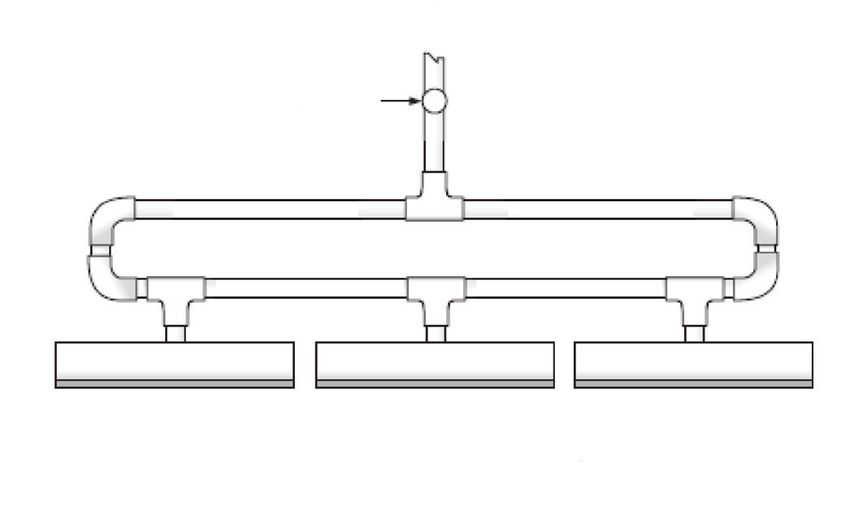
Zodiac® Sheer Descent® and Fiberfall® Water Features | Installation and Operation Manual             ENGLISH                   Page 3

                                                        Table of Contents

Section 1. Important Safety Instructions............ 4                       Section 5. Start Up............................................ 15
1.1    Safety Instructions..................................... 4            5.1      Start Up Instructions.................................. 15

Section 2. General Installation Requirements... 8                            Section 6. General Maintenance and
2.1    Preparation Instructions............................. 8                          Troubleshooting................................ 16
2.2    Excavation and Steel                                                  6.1      Troubleshooting......................................... 16
       Modifications.............................................. 8         6.2      Freeze Protection and Winterizing............. 16
2.3    Concrete Installation and Modifications..... 9
       2.3.1      Positioning the Waterfall................10
       2.3.2      Finishing the Waterfall...................10

Section 3. Pump Sizing and Installation
           Options............................................. 10
3.1    Existing Pool Filter Pump Installation......... 11
3.2    Separate Pump for the Sheer Descent
       Waterfall..................................................... 11

Section 4. Plumbing the Sheer Descent
           Waterfall........................................... 12
4.1    Waterfall Return Line Plumbing................. 12
4.2    Plumbing a Single Unit............................... 13
4.3    Plumbing Multiple Units............................. 13
4.4    Cutting the Lip for Radius or Custom
       Installations................................................ 13
4.5    Sheer Descent Waterfall Radius Cut
       Guideline.................................................... 14
Page 4 ENGLISH Zodiac® Sheer Descent® and Fiberfall® Water Features | Installation and Operation Manual
Section 1. Important Safety Instructions
READ AND FOLLOW ALL INSTRUCTIONS
1.1 Safety Instructions
All work must be performed by a contractor who is licensed and qualified in pool equipment and conform to all national,
state, and local codes. When installing and using this equipment, basic safety precautions should always be followed,
including the following:
WARNING
RISK OF SUCTION ENTRAPMENT HAZARD, WHICH, IF NOT AVOIDED CAN RESULT IN SERIOUS
INJURY OR DEATH. Do not block pump suction as this can cause severe injury or death. Suction outlet
(drain) covers must be certified to ANSI/ASME A112.19.8.
WARNING
To reduce the risk of injury, do not permit children to use this product.
WARNING
To reduce the risk of property damage or injury, do not attempt to change the backwash (multiport, slide,
or full flow) valve position with the pump running.
WARNING
Due to the potential risk of fire, electric shock, or injuries to persons, Zodiac Equipment must be installed
in accordance with the National Electric Code, all local electrical and safety codes, and the Occupational
Safety and Health Act (OSHA). Copies of the National Electrical Code may be ordered from the National
Fire Protection Association (NFPA) online at www.nfpa.org or call 617-770-3000, or contact your local
government inspection agency.
WARNING
Incorrectly installed equipment may fail, causing severe injury or property damage.
WARNING
• Do not connect system to an unregulated city water system or other external source of pressurized water
producing pressures greater than 35 PSI.
• Trapped air in system can cause the pump and/or filter lid to be blown off which can result in death,
serious personal injury, or property damage. Be sure all air is out of system before operating.Zodiac® Sheer Descent® and Fiberfall® Water Features | Installation and Operation Manual ENGLISH Page 5
WARNING
To minimize risk of severe injury or death the filter and/or pump should not be subjected to the piping
system pressurization test.
Local codes may require the pool piping system to be subjected to a pressure test. These requirements
are generally not intended to apply to the pool equipment such as filters or pumps.
Zodiac pool equipment is pressure tested at the factory.
If however the WARNING cannot be followed and pressure testing of the piping system must include the
filter and/or pump BE SURE TO COMPLY WITH THE FOLLOWING SAFETY INSTRUCTIONS:
• Check all clamps, bolts, lids, lock rings and system accessories to ensure they are properly installed
and secured before testing.
• RELEASE ALL AIR in the system before testing.
• Water pressure for test must NOT EXCEED 35 PSI (241 kPa).
• Water temperature for test must NOT EXCEED 100°F (38°C).
• Limit test to 24 hours. After test, visually check system to be sure it is ready for operation.
• Notice: These parameters apply to Zodiac equipment only. For non-Zodiac equipment, consult equip-
ment manufacturer.
WARNING
Chemical spills and fumes can weaken pool/spa equipment. Corrosion can cause filters and other equipment
to fail, resulting in severe injury or property damage. Do not store pool chemicals near your equipment.Page 6 ENGLISH Zodiac® Sheer Descent® and Fiberfall® Water Features | Installation and Operation Manual
WARNING
Pump suction is hazardous and can trap and drown or disembowel bathers. Do
not use or operate swimming pools, spa, or hot tubs if a suction outlet cover is
missing, broken, or loose. The following guidelines provide information for pump
installation that minimizes risk of injury to users of pools, spas, and hot tubs:
Entrapment Protection - The pump suction system must provide protection against the hazards of
suction entrapment.
Suction Outlet Covers - All suction outlets must have correctly installed, screw-fastened covers in place.
All suction outlet (drain) covers must be maintained. Drain covers must be listed/certified to ANSI/ASME
A112.19.8. They must be replaced if cracked, broken, or missing.
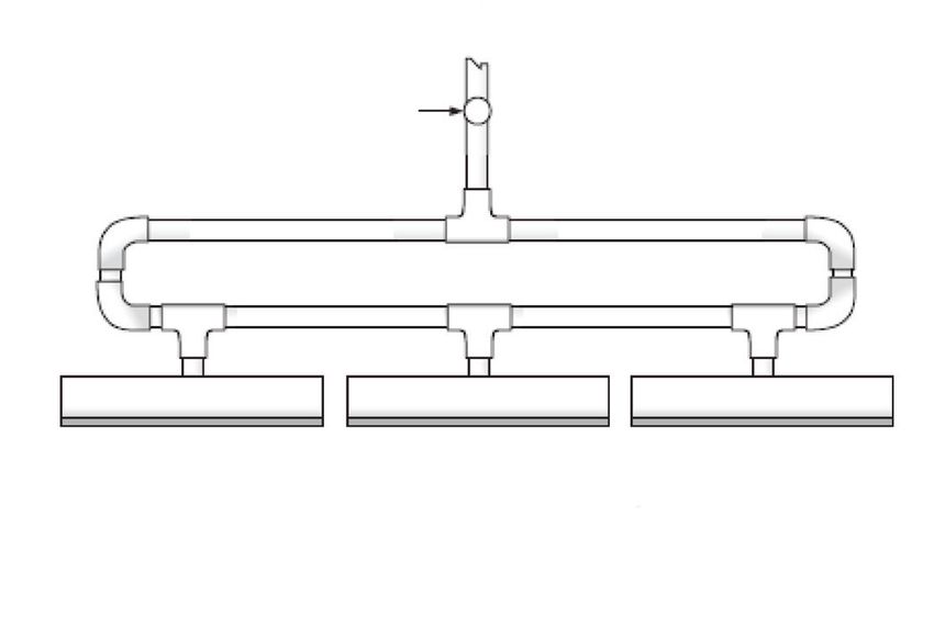
Number of Suction Outlets Per Pump - Provide at least two hydraulically balanced main drains, with
covers, as suction outlets for each circulating pump suction line. The centers of the main drains (suction
outlets) on any one suction line must be at least three feet apart, center to center. (See Figure 1 on
page 7.)
The system must be built to include at least two suction outlets (drains) connected to the pump whenever
the pump is running. However, if two main drains run into a single suction line, the single suction line
may be equipped with a valve which will shut off both main drains from the pump. The system shall be
constructed such that it shall not allow for separate or independent shutoff or isolation of each drain. (See
Figure 1 on page 7.)
More than one pump can be connected to a single suction line as long as the requirements above are
met.
Water Velocity - The maximum water velocity through the suction fitting or cover for any suction outlet
must be 1.5 feet per second unless the outlet complies with the latest version of ANSI/ASME A112.19.8,
the standard for Suction Fittings For Use in Swimming and Wading Pools, Spas, Hot Tubs, and Catch
Basins. In any case, do not exceed the suction fitting’s maximum designed flow rate.
If 100% of the pump’s flow comes from the main drain system, the maximum water velocity in the pump
suction hydraulic system must be six feet per second or less even if one main drain (suction outlet) is
completely blocked. The flow through the remaining main drain(s) must comply with the latest ANSI/ASME
A112.19.8, the standard for Suction Fittings For Use in Swimming and Wading Pools, Spas, Hot Tubs,
and Catch Basins.
Testing and Certification - Suction outlet covers must have been tested by a nationally recognized testing
laboratory and found to comply with the latest ANSI/ASME A112.19.8, the standard for Suction Fittings
For Use in Swimming and Wading Pools, Spas, Hot Tubs, and Catch Basins.
Fittings - Fittings restrict flow; for best efficiency use fewest possible fittings (but at least two suction
outlets).
Avoid fittings which could cause an air trap.
Pool cleaner suction fittings must conform to applicable International Association of Plumbing and
Mechanical Officials (IAPMO) standards.Zodiac® Sheer Descent® and Fiberfall® Water Features | Installation and Operation Manual ENGLISH Page 7
At Least
3 Feet
Listed/certified to Listed/certified to
ANSI/ASME A112.19.8 ANSI/ASME A112.19.8
Anti-entrapment Anti-entrapment
Cover/Grate or Suction Cover/Grate or Suction
Fitting, screw-fastened Fitting, screw-fastened
to Main Drain Sump No valves between to Main Drain Sump
Tee and Main Drains
Suction Outlet Suction Outlet
(Main Drain) (Main Drain)
Pump
Valves OK between
pump and Tee
Figure 1. Number of Suction Outlets Per PumpPage 8 ENGLISH Zodiac® Sheer Descent® and Fiberfall® Water Features | Installation and Operation Manual
Section 2. General Installation the opening during the entire installation, or damage to
the unit, which would effect its ability to perform, may
Requirements
occur.
This document gives instructions for installing the To properly install this product please review the
Zodiac Sheer Descent and FiberFall water features. following installation and maintenance instructions.
Read through the instructions completely before starting
the procedure. 2.2 Excavation and Steel Modifications
It is recommended that the area designated for the Sheer
2.1 Preparation Instructions Descent waterfall be marked off with colored stakes,
During all phases of the installation, care should be yellow construction ribbon, or similar material during
taken not to damage the Sheer Descent waterfall. the framing process, prior to excavation.
Keep the unit in the original packaging, laying on a
In preparation for the installation of the steel rebar,
flat surface and protected from sunlight until the site is
mark the EXACT area designated for the Sheer Descent
prepared for permanent installation.
waterfall. To allow room for notching the bond beam
The Sheer Descent waterfall is available in standard and installing the unit, offset the steel pattern by 4½
sizes from 1 foot to 8 feet in length and is shipped inches (11.4 cm) below the original form and 1 inch (2.5
complete with lip protector installed in the opening cm) on both ends of the Sheer Descent waterfall. For
of the waterfall. See Figure 2. The lip protector keeps example, if the Sheer Descent waterfall is 3 feet (0.9 m)
the spillway opening clean and damage free. DO NOT in length, offset the steel pattern to measure 4½ inches
REMOVE THE LIP PROTECTOR until the startup of (11.4 cm) down from the top of the frame and 50 inches
the pool equipment. The lip protector must be left in (127 cm) in length (this allows 1 inch (2.5 cm) of space
1
Components
1. Lip Water flow
through unit.
2. X-Baffle™ Brand Turbulence Suppressor
3. Inlet
2
4. Lip Protector
5. Lens Chamber with Fiber Cable (FiberFall only)
1
3 Side Cutaway View
4
1
3
5 4
Figure 2. Sheer Descent and FiberFall ComponentsZodiac® Sheer Descent® and Fiberfall® Water Features | Installation and Operation Manual ENGLISH Page 9
on each side of the Sheer Descent unit). For FiberFalls, 2.3 Concrete Installation and
offset the steel for the unit length plus 6 inches (15.2 Modifications
cm) on the left to accommodate the lens chamber and For Sheer Descent, notch the bond beam 4-1/2 inches
fiber cable, or 6 inches (15.2 cm) on both sides for (11.4 cm) deep and 1 inch (2.5 cm) longer than the
double-chambered units. See Figure 3. width of the unit. For FiberFalls, notch for unit length
plus 6 inches (15.2 cm) on the left to accommodate the
lens chamber and fiber cable, or 6 inches (15.2 cm) on
Steel off set both sides for double-chambered units. FiberFall also
requires a 1 inch (2.5 cm) conduit stub-up in the beam
Finished notch in beam
for the fiber cable(s). See Figure 4.
3½"
Top of raised bond beam
For vinyl and fiberglass pools, configure block to match
gunite beam installation.
After notching the beam (setting blocks), do the
following steps: (Refer to Figure 5.)
1. Determine water fall installation level with bender
4½" wide x 4½"
deep notch board.
Note: Notching of the bond beam is the next 2. Tack bender board at notch 1-3/8 inches (3.5 cm)
step in the process. The change to the
steel will make the notch a simple procedure. below bottom of coping.
3. Cement back of board.
Figure 3. Excavation and Steel Installation
Sheer Descent
Bond
Beam
FiberFall
Bond
Lens Chamber Beam
4-1/2" with Cable
4-1/2"
Unit Length Plus 1"
Unit Length Plus 6" to Left
Figure 4. Concrete Installation
Bond Beam
Bender
Board
Bender
Board
1-3/8”
Cement
Figure 5. Install Bender BoardPage 10 ENGLISH Zodiac® Sheer Descent® and Fiberfall® Water Features | Installation and Operation Manual
2.3.1 Positioning the Waterfall for thicker finishes like rock or brick) to ensure
lip will be 1/4 inch (0.64 cm) past finished pool
CAUTION
wall.
Make sure that the waterfall is positioned correctly.
Do not point the lip downwards. Refer to Figure 6. 3. Tap in and level.
Correct Incorrect 4. Apply 5/8 inches (1.6 cm) of cement finishing
to top, sides and back of waterfall to encase unit.
Inlet Slope top surface slightly towards back, 1/4
Lip Inlet
bubble on level. Refer to Figure 8.
5. Remove excess cement from front of waterfalls.
2.3.2 Finishing the Waterfall
1. Use thin-set to install coping material onto cement
Lip on top of waterfall. Tap in and level. Refer to
Figure 9.
Figure 6. Position the Waterfall Correctly in the
Notch 2. Remove bender board.
1. Create a bed of cement mortar in the notch to
provide a solid base for the waterfall. Refer to Section 3. Pump Sizing and
Figure 7. Installation Options
2. Set the unit into the mortar bed. The lip should
NOTE Make sure the cuts in the beam are properly
extend 1 inch (2.5 cm) beyond gunite (or more
completed before proceeding.
3 4 5
1 2
Position the Waterfall Make Sure the Lip Extends 1 inch
(or more) beyond the Gunite.
Figure 7. Positioning the Waterfall in Notch
Figure 8. Slope Surface Towards Back of WaterfallZodiac® Sheer Descent® and Fiberfall® Water Features | Installation and Operation Manual ENGLISH Page 11
Completed Installation - Front Completed Installation - Back
Figure 9. Finishing the WaterFall Installation
One of the advantages of the Sheer Descent waterfall is Feet of Projection
the ability to provide a continuous sheet of water with 3
1 2
a minimum of water flow. A standard 4 foot model, for
example, requires only 48 gallons per minute (gpm)
to operate. In order to size your pump properly, refer
Feet of Elevation
to the Water Flow Requirement Chart. In most cases, 2 NOTE Do not
install the waterfall
a properly sized standard swimming pool pump will more than 3 feet
above the water
operate the Sheer Descent waterfall and filter the pool surface or the
with little loss of total water turnover. As a general 1 laminar sheet will
start to break up.
rule of thumb, the Sheer Descent waterfall requires
approximately 12 gallons per minute per foot with
little head loss. For a more dramatic effect, more water
gallonage can be applied to project the waterfall further 7 9 1012 15 20
away from the wall. Refer to Figure 10. Gallons per minute per foot
Guideline is for 1ft. to 8ft. models
NOTE When plumbing multiple falls, add the total
length of waterfalls together to determine Figure 10. Water Flow Requirement Chart
GPM required. e.g. When plumbing two 6 foot
units, you now have 12 feet of waterfall, which feed line in a minimum of 1½ inches PVC schedule 40
requires 144 gallons per minute. pipe. Units above 5 feet in length need a minimum of
2 inch plumbing.
3.1 Existing Pool Filter Pump Installation
The installation of the Sheer Descent waterfall using the 3.2 Separate Pump for the Sheer
main pool filter pump is the most common plumbing Descent Waterfall
system, due to the unique low flow aspect of the If multiple waterfalls are being installed, or a Sheer
waterfall system. Simply plumb a three way valve on Descent waterfall 6 feet or longer is being installed,
the return line, after the filter, and plumb the waterfall we recommend installing a separate pump and filter.Page 12 ENGLISH Zodiac® Sheer Descent® and Fiberfall® Water Features | Installation and Operation Manual
7”
balanced between the waterfall and return back to the
pool, is also required. See Figure 12.
Section 4. Plumbing the Sheer
Descent Waterfall
4.1 Waterfall Return Line Plumbing
9 3/4” NOTE If the waterfall flow rate exceeds more that
40% of the filtration flow, a separate pump is
recommended.
The waterfall feed line, from either the main filter pump
or a separate pump, should be plumbed with a pipe
size capable of handling the required flow rate of the
Figure 11. Sheer Descent Filter/Strainer (p/n 3456) waterfall. See Table 1.
When plumbing a pump dedicated for use by the Sheer NOTE Two inch plumbing or larger is suggested for
Descent, a separate suction line to the pool must be waterfalls over 5 feet in total length. Refer
plumbed. This should be plumbed in a minimum of 2 to Hydraulic Guideline Chart, Table 1, for
inch schedule 40 pipe. specifications. The feed line should end near
the back of the bond beam near the center of
WARNING the waterfall location.
For safety, at least two anti entrapment suction
Table 1. Hydraulic Guideline Chart
covers must be installed. It is recommended that they
be 18 inches (38.1 cm) above the pool floor and must Suction (SUC) and Discharge (DIS)
be at least 3 feet (0.9 m) apart with no valves be- Water Flow Chart for PVC
tween the “Tee” and any of the suction covers. Pipe Size Max SUC Flow* Max DIS Flow**
1½” 37 gpm (140 lpm) 50 gpm (189 lpm)
A Sheer Descent filter/strainer (p/n 3456), or equivalent,
must be installed on the return side of the pump, 2” 62 gpm (235 lpm) 82 gpm (310 lpm)
between the pump and the waterfall. Refer to Figure 11. 2½” 88 gpm (333 lpm) 117 gpm (443 lpm)
FILTER IS REQUIRED for separate pump installations, 3” 136 gpm (515 lpm) 180 gpm (681 lpm)
as large debris must not be allowed to enter the waterfall
4” 234 gpm (886 lpm) 313 gpm (1185 lpm)
unit. For installations requiring up to 60 gallons (227 l)
per minute, use one Sheer Descent filter/strainer. For * Max SUC Flow based on 6 feet (1.8 m) per second velocity.
** Max DIS Flow based on 8 feet (2.4 m) per second velocity.
higher water requirements, use two or more filters
plumbed in parallel. A separate return line, with a three It is important to have a valve located in a convenient
way valve plumbed in such a way that water can be location on the feed line to regulate the flow of water to
Conventional
Concrete Decking
Cantilever Edge
Sheer Descent Unit
Tile
Water Line
Separate Return
NOTE: At least two (2) (anti-entrapment) to Pool
suction outlets provided with covers
which are listed/certified as complying Zodiac Jandy®
with ANSI/ASME A112.19.8-2007 or later. Three Way Valve
Suction outlets (drains) should be Suction Line
installed in accordance with
ANSI/APSP-7, the American National
Standard for Suction Entrapment
Avoidance in Swimming Pools, Wading
Pools, Spas, Hot Tubs, and Catch Basins.
Sheer Descent
Filter/Strainer Filter
Pump
Figure 12. Filter Pump InstallationZodiac® Sheer Descent® and Fiberfall® Water Features | Installation and Operation Manual ENGLISH Page 13
NOTE A flow control valve must be plumbed in a
Line bypass to pool
convenient location on the supply line for
regulation of the water supply to the unit. See
Figure 14.
Zodiac Jandy®
three way valve
Water to 4.3 Plumbing Multiple Units
sheer descent
Pump Plumbing two or more Sheer Descent waterfalls
Filter
together is done in exactly the same way as the
installation procedure for a single unit, explained
previously, with the exception that additional two-way
valves are required for each Sheer Descent waterfall.
Suction See Figure 15. The loop plumbing option can also be
from pool used for two or more units. See Figure 16.
Make sure no debris is in any of
Figure 13. Three-Way Valve Plumbing Setup the plumbing lines in the unit
the Sheer Descent waterfall. A Zodiac Jandy® three-
way valve is suggested to be used as the “T” from the
return line of the pool to the Sheer Descent waterfall.
A properly plumbed valve in that position will allow
full control of the water to the Sheer Descent, as well
as to the rest of the pool. In most cases, this valve can Zodiac
be located after the filter near the equipment pad. See Jandy ValveTM
Figure 13.
NOTE All water to the Sheer Descent must be filtered.
Those systems using a separate pump must Option #1 - Sheer Descent
use our separate energy filter (p/n 3456) or waterfall back feed plumbing
equivalent to prevent debris from entering the for multiple units.
Sheer Descent unit.
Figure 15. Multiple Sheer Descent Plumbing Setup
4.2 Plumbing a Single Unit
Make sure plumbing lines are clear of debris.
All back feed Sheer Descent waterfalls have the
equivalent of standard 1½ inch inside and 2 inches Zodiac
outside pipe protruding from the back of the unit. For Jandy® Valve
waterfalls 1 through 8 feet in length, this fitting is
located in the center of the back of the waterfall.
Standard 1½ inch and 2 inch PVC fittings will glue
in and over the 1½ inch slip by 2 inch insert fitting
provided on all Sheer Descent waterfalls.
Ensure plumbing lines to unit are clear of debris. Option #2 - Sheer Descent waterfall
Ensure plumbing is properly sized. back feed loop plumbing for
multiple units.
Figure 16. Multiple Sheer Descent Loop Plumbing
Setup
Notch in beam Beam 4.4 Cutting the Lip for Radius or Custom
Installations
Back Feed plumbing for The extended lip Sheer Descent waterfall can be custom
units 1 feet through 8 feet. cut in the field to meet specific needs, such as radius,
irregular shapes, etc. In order to custom fit the waterfall,
Figure 14. Single Sheer Descent Plumbing Setup carefully measure the amount of extended lip to bePage 14 ENGLISH Zodiac® Sheer Descent® and Fiberfall® Water Features | Installation and Operation Manual
removed. Remember to leave enough room for tile and
2" (5.1 cm) minimum
thin set, so the deepest edge of the radius cut will not be
Concave Radius
recessed from the tile line.
NOTE Never remove more than 4” (10.2 cm) of the
¼" (.64 cm)
extended lip, always leaving a minimum of 2” ½" (1.3cm)
(5.1 cm) of lip. See Figure 17.
6"
(15.2 cm)
Remove the lip protector prior to cutting the waterfall. Break off lip supports Support
1" (2.5 cm) from lip of waterfall
Remember to REPLACE THE LIP PROTECTOR after removal tool
¾" (1.9 cm)
cutting the radius to protect the fall from construction
debris. Concave Radius
The waterfall must be cut with a coarse tooth saw
blade. Caution must be taken to make the cut as smooth
as possible to avoid a jagged edge. After cutting the
waterfall, insert the spacer removal tool (included in
product packaging) 1 inch (2.5 cm) into the waterfall Insert Lip Protector
opening. Move the tool around the opening. If the tool
hits a support, use the notch in the tool to remove the
support. See Figure 18. Make sure all supports within
1 inch (2.5 cm) of lip opening are removed. DO NOT Figure 18. Custom Installations - Concave Radius
LEAVE THE LOOSE SUPPORT SECTION IN THE
continue installation, following the installation
WATERFALL.
instructions for the standard Sheer Descent waterfall.
After removing sections of the supports, use a 1/8 inch
(0.32 cm) flat file and coarse grade sandpaper to smooth 4.5 Sheer Descent Waterfall Radius Cut
the edges of the waterfall, follow with a fine grade of Guideline
sandpaper to get the edge as smooth as possible. A
sanding block is recommended to avoid rounding the NOTE Never remove more than 4” (10.2 cm) of the
edges of the waterfall. extended lip, always leaving a minimum of 2”
(5.1 cm) of lip. The top of the beam, where the
Insert the lip protector back into the opening and Sheer Descent unit is to be installed, should
be a minimum of 9” (22.9 cm) thick. When
designing custom curves for the Sheer Descent
Convex Radius Extended Lip models, please refer to Table
2, for radius guidelines to select the correct
Sheer Descent model. Super Radius models
accommodate very tight radius curves and are
available by special order. Refer to Figure 19.
Break off lip spacers
1" from lip of waterfall Spacer Do not
removal tool remove more
than 4" (10.2 cm)
Sheer Descent Waterfall
Convex Radius extended lip radius installation
Insert Lip Protector
Figure 19. Extended Lip Radius Installation
Figure 17. Custom Installations - Convex RadiusZodiac® Sheer Descent® and Fiberfall® Water Features | Installation and Operation Manual ENGLISH Page 15
Table 2. Sheer Descent Radius Chart
Use the chart below to ensure the Sheer Descent length, lip and radius are available.
S h e e r D e s c e n t L e n g t h
12” 18” 24” 36” 48” 60” 72” 84” 96”
1’ 6” Lip 6” Lip Custom Custom N/A N/A N/A N/A N/A
1.5’ 6” Lip 6” Lip 6” Lip Custom Custom N/A N/A N/A N/A
2’ 6” Lip 6” Lip 6” Lip 12” Lip Custom Custom N/A N/A N/A
2.5’ 6” Lip 6” Lip 6” Lip 12” Lip Custom Custom Custom N/A N/A
3’ 6” Lip 6” Lip 6” Lip 6” Lip 12” Lip Custom Custom Custom N/A
3.5’ 6” Lip 6” Lip 6” Lip 6” Lip 12” Lip Custom Custom Custom Custom
4’ 6” Lip 6” Lip 6” Lip 6” Lip 12” Lip 12” Lip Custom Custom Custom
4.5’ 6” Lip 6” Lip 6” Lip 6” Lip 12” Lip 12” Lip Custom Custom Custom
5’ 6” Lip 6” Lip 6” Lip 6” Lip 12” Lip 12” Lip Custom Custom Custom
S i z e
5.5’ 6” Lip 6” Lip 6” Lip 6” Lip 6” Lip 12” Lip Custom Custom Custom
6’ 6” Lip 6” Lip 6” Lip 6” Lip 6” Lip 12” Lip 12” Lip Custom Custom
6.5’ 6” Lip 6” Lip 6” Lip 6” Lip 6” Lip 12” Lip 12” Lip Custom Custom
R a d i u s
7’ 6” Lip 6” Lip 6” Lip 6” Lip 6” Lip 12” Lip 12” Lip Custom Custom
7.5’ 6” Lip 6” Lip 6” Lip 6” Lip 6” Lip 12” Lip 12” Lip Custom Custom
8’ 6” Lip 6” Lip 6” Lip 6” Lip 6” Lip 6” Lip 12” Lip 12” Lip Custom
8.5’ 6” Lip 6” Lip 6” Lip 6” Lip 6” Lip 6” Lip 12” Lip 12” Lip Custom
9’ 6” Lip 6” Lip 6” Lip 6” Lip 6” Lip 6” Lip 12” Lip 12” Lip Custom
9.5’ 6” Lip 6” Lip 6” Lip 6” Lip 6” Lip 6” Lip 12” Lip 12” Lip 12” Lip
10’ 6” Lip 6” Lip 6” Lip 6” Lip 6” Lip 6” Lip 12” Lip 12” Lip 12” Lip
10.5’ 6” Lip 6” Lip 6” Lip 6” Lip 6” Lip 6” Lip 12” Lip 12” Lip 12” Lip
11’ 6” Lip 6” Lip 6” Lip 6” Lip 6” Lip 6” Lip 6” Lip 12” Lip 12” Lip
11.5 6” Lip 6” Lip 6” Lip 6” Lip 6” Lip 6” Lip 6” Lip 12” Lip 12” Lip
12’ 6” Lip 6” Lip 6” Lip 6” Lip 6” Lip 6” Lip 6” Lip 12” Lip 12” Lip
12.5’ 6” Lip 6” Lip 6” Lip 6” Lip 6” Lip 6” Lip 6” Lip 12” Lip 12” Lip
13’ 6” Lip 6” Lip 6” Lip 6” Lip 6” Lip 6” Lip 6” Lip 12” Lip 12” Lip
Section 5. Start Up 4. Allow for air to clear the lines. This should only
take a few minutes. The Sheer Descent waterfall
unit should now provide a clear, continuous sheet
5.1 Start Up Instructions
of water.
After the swimming pool is completed and filled
with water, the Sheer Descent waterfall is ready to be 5. If a separate pump was installed, make sure
activated. all valves are open prior to starting the pump.
ENSURE ALL LINES ARE CLEAR OF DEBRIS
1. REMOVE THE LIP PROTECTOR NOW. This
BEFORE STARTING. Start the pump and allow
must be done before water is diverted to the
water to circulate through the separate filter
waterfall. Also, ensure the opening is clean and
system and return line. Slowly open the valve to
clear of any debris.
the waterfall and regulate to the desired setting.
2. Turn the pump on. If the waterfall is plumbed with Allow a few minutes to purge all air from the
the main pool filter pump, allow the pump to run a lines.
few minutes to clear the lines of debris.
3. Slowly open the regulating valve and supply water
to the Sheer Descent unit. Adjust the flow of water
until the sheet of water extends out onto the pool
surface.Page 16 ENGLISH Zodiac® Sheer Descent® and Fiberfall® Water Features | Installation and Operation Manual
Section 6. General Maintenance and
Troubleshooting
Before proceeding, make sure the pump system is fully
functional and activated. Also, ensure all air is purged
from plumbing lines.
6.1 Troubleshooting
Problem Cause Solution
The waterfall is not Debris has lodged in the Use a credit card or similar object and gently position it
completely smooth. A gap opening of the waterfall. inside the opening while the waterfall is on. Slide it along
or gaps in the sheet of the the opening to the point where the debris is located and
waterfall is present. gently pull the debris through the opening. Do not use a
metal tool.
Dirty filter, pump basket Clean filter, pump basket or both.
or both has slowed down
the flow to below proper
standards.
Waterfall flow valve(s) are Adjust water flow valve(s).
out of adjustment.
Waterfall radius was field Refer to Section 4.4 for proper spacer removal
cut and spacers were not instructions.
removed.
Where multiple waterfalls The water supplied to Adjust the valves for each waterfall until the proper
are installed, one of the the units is not properly effect and balance is achieved. See Figure 15 for valve
waterfalls is stronger than balanced. location.
the other(s).
Improper loop plumbing Correct loop plumbing installation. Refer to Figure 16 for
installation. proper loop plumbing setup.
6.2 Freeze Protection and Winterizing
In order to prevent freeze damage to the system, the
plumbing to the unit must be installed so water drains
easily from the system. The Sheer Descent and Fiber
Fall waterfalls have been engineered to allow only a
minimum of water to stay in the unit as long as the
plumbing is installed properly. Blow out all water from
the pipes and Sheer Descent or Fiber Fall unit. Follow
the normal procedures for winterizing.
Zodiac Pool Systems, Inc.
2620 Commerce Way, Vista, CA 92081
1.800.822.7933 | www.ZodiacPoolSystems.com
Zodiac Pool Systems Canada, Inc.
2115 South Service Road West, unit 3
Oakville, ON L6L 5W2
1.888.647.4004 | www.zodiacpoolsystems.ca
©2011 Zodiac Pool Systems, Inc. H0347100 Rev C
ZODIAC ® is a registered trademark of Zodiac International, S.A.S.U., used under license.
All trademarks referenced herein are the property of their respective owners.GUIDE D’INSTALLATION ET
DE FONCTIONNEMENT
English | Français
Cascades Sheer
Descent® et
FiberFall® Zodiac
AVERTISSEMENT
POUR VOTRE SÉCURITÉ – L’installation et l’entretien de ce produit doivent être effectués
par un technicien autorisé et qualifié pour la réparation des équipements de piscine par les
autorités compétentes du territoire dans lequel ledit produit est installé lorsque de telles
exigences locales ou provinciales sont édictées. Si aucune exigence locale, provinciale ou
territoriale n’est disponible, l’agent d’entretien doit être un professionnel avec suffisamment
d’expérience dans l’installation et la maintenance d’équipement de piscine pour appliquer
correctement les consignes du présent manuel. Avant d’installer ce produit, lisez toutes les
consignes de mise en garde et les instructions incluses avec ce produit et respectez-les.
Le non-respect des avertissements et des instructions pourrait causer des dommages
matériels, des blessures graves ou même un décès. L’installation et/ou l’utilisation inappropriée
H0347100 Rev C
annuleront la garantie.Cascades Sheer Descent® et Fiberfall® Zodiac® | Guide d’utilisation et mode d’emploi FRANÇAIS Page 19
Table des matières
Section 1. Consignes de sécurité importantes .. 20 Section 4. Raccordement de la cascade
1.1 Consignes de sécurité .............................. 20 Sheer Descent ................................. 28
4.1 Conduite de retour pour la cascade .......... 28
Section 2. Exigences générales pour 4.2 Raccordement d’une cascade unique ....... 29
l’installation ...................................... 24 4.3 Raccordement de plusieurs cascades....... 29
2.1 Consignes pour la préparation .................. 24 4.4 Coupe du bord pour le rayon ou les
2.2 Travaux d’excavation et modifications à installations personnalisées ...................... 29
l’acier d’armature....................................... 24 4.5 Directives pour la coupe du rayon de la
2.3 Installation du béton et modifications ........ 25 cascade Sheer Descent ............................ 30
2.3.1 Positionnement de la cascade ........ 26 Section 5. Démarrage ....................................... 30
2.3.2 Finition de la cascade ..................... 26 5.1 Consignes pour le démarrage ................... 30
Section 3. Puissance de la pompe et options Section 6. Entretien général et dépannage ...... 32
d’installation ..................................... 26
6.1 Dépannage ............................................... 32
3.1 Installation avec une pompe existante ...... 27 6.2 Protection contre le gel et hivernage ........ 32
3.2 Installation avec une pompe dédiée pour
la cascade Sheer Descent ........................ 27Page 20 FRANÇAIS Cascades Sheer Descent® et Fiberfall® Zodiac® | Guide d’utilisation et mode d’emploi
Section 1. Consignes de sécurité importantes
LIRE ET SUIVRE TOUTES LES CONSIGNES
1.1 Consignes de sécurité
Tous les travaux doivent être effectués par un entrepreneur qui est autorisé et qualifié en matière d’équipement de piscine et qui
se conforme à tous les codes nationaux, d’État, provinciaux, territoriaux et locaux. Lors de l’installation et de l’utilisation de cet
équipement, des précautions de base doivent toujours être suivies, entre autres :
AVERTISSEMENT
RISQUE DE PIÉGEAGE DANS LA CONDUITE D’ASPIRATION QUI, SI NON ÉVITÉ, POURRAIT
ENTRAÎNER DES BLESSURES GRAVES OU LA MORT. Ne pas bloquer l’aspiration de la pompe, car
ceci peut causer des blessures graves ou un décès. Les couvercles des sorties d’aspiration (vidange)
doivent être certifiés à la norme ANSI/ASME A112.19.8.
AVERTISSEMENT
Pour réduire le risque de blessure, ne pas permettre aux enfants d’utiliser ce produit.
AVERTISSEMENT
Pour réduire le risque de dommages matériels et de blessures, ne pas essayer de changer la position
de la vanne (multivoies, de glissement ou de passage intégral) de lavage à contre-courant pendant le
fonctionnement de la pompe.
AVERTISSEMENT
En raison du risque potentiel d’incendie, de décharge électrique ou blessures aux personnes, l’équipement
Zodiac doit être installé en conformité avec le Code national de l’électricité, tous les codes locaux d’électricité
et de sécurité et à la Loi sur la sécurité professionnelle et la santé (OSHA). Des copies du Code national
de l’électricité pourront être commandées en ligne de l’Association nationale de la protection contre les
incendies (NFPA) sur le site Web www.nfpa.org ou en appelant le +1 (617) 770-3000 ou en communiquant
avec votre agence locale d’inspection gouvernementale.
AVERTISSEMENT
Un équipement mal installé peut être défaillant et peut ainsi causer des blessures graves ou des dommages
matériels.
AVERTISSEMENT
• Ne pas raccorder le système à un réseau urbain de distribution d’eau non réglementé ou à une autre
source externe d’eau sous pression produisant des pressions supérieures à 241 kPa (35 PSI).
• Le piégeage d’air dans le circuit peut provoquer une ouverture explosive du couvercle du filtre pouvant
causer un décès, de graves blessures personnelles ou des dommages matériels. S’assurer que tout l’air
est bien expulsé du système avant de l’utiliser.Cascades Sheer Descent® et Fiberfall® Zodiac® | Guide d’utilisation et mode d’emploi FRANÇAIS Page 21
AVERTISSEMENT
Pour réduire les risques de blessures graves, voire de mort, le filtre et/ou la pompe ne doivent pas être
soumis au test de mise sous pression du système de tuyauterie.
Les codes locaux peuvent exiger l’application d’un essai de pression au système de tuyauterie de la
piscine. Ces exigences ne s’appliquent généralement pas à l’équipement de piscine, tel que les filtres
ou les pompes.
L’équipement de piscine Zodiac a fait l’objet d’essais de mise sous pression en usine.
Toutefois, si cet AVERTISSEMENT ne peut pas être suivi et que les essais de mise sous pression du
système de tuyauterie doivent inclure le filtre et/ou la pompe, S’ASSURER QUE LES CONSIGNES DE
SÉCURITÉ SUIVANTES SONT RESPECTÉES :
• Vérifier les serre-joints, les boulons, les couvercles, les bagues de retenue et les accessoires du
système pour s’assurer qu’ils sont convenablement installés et fixés avant d’effectuer un essai.
• ENLEVER TOUT L’AIR du système avant l’essai.
• La pression de l’eau pour l’essai ne doit PAS DÉPASSER 241 kPa (35 PSI).
• La température de l’eau pendant l’essai NE DOIT PAS DÉPASSER 38°C (100°F).
• Limiter l’essai à 24 heures. Après le test, vérifier visuellement le système pour s’assurer qu’il est prêt
à fonctionner.
• Avis : Ces paramètres s’appliquent uniquement à l’équipement Zodiac. Pour l’équipement non
fabriqué par Zodiac, consulter le fabricant.
AVERTISSEMENT
Des déversements et vapeurs chimiques peuvent affaiblir l’équipement de la piscine ou du spa. La corrosion
peut entraîner la défaillance des filtres et autre équipement, ce qui peut entraîner des blessures graves ou
des dommages matériels. Ne pas entreposer de produits chimiques de piscine près de votre équipement.Page 22 FRANÇAIS Cascades Sheer Descent® et Fiberfall® Zodiac® | Guide d’utilisation et mode d’emploi
AVERTISSEMENT
L’aspiration de la pompe est dangereuse et peut piéger, noyer ou éviscérer les
baigneurs. Ne pas utiliser ni faire fonctionner les piscines, les spas ou les jacuzzis
si un couvercle de sortie d’aspiration est absent, brisé ou instable. Les directives
suivantes fournissent l’information d’installation de la pompe qui permet de réduire le plus
possible les risques de blessures aux utilisateurs des piscines, des spas et des jacuzzis :
Protection contre le piégeage - Le système d’aspiration de la pompe doit fournir une protection contre
les dangers de piégeage par aspiration.
Couvercles de sorties d’aspiration - Toutes les sorties d’aspiration doivent être correctement installées et
les couvercles bien vissés en place. Tous les couvercles de sortie d’aspiration (canalisation d’évacuation)
doivent être entretenus. Les couvercles de vidange doivent être indiqués et certifiés à la norme ANSI/
ASME A112.19.8. Ils doivent être remplacés s’ils sont fissurés, brisés ou manquants.
Nombre de sorties d’aspiration par pompe - Prévoir au moins deux (2) canalisations principales de vidange
hydrauliquement équilibrées, avec couvercles, comme sorties d’aspiration pour chaque conduite d’aspiration
de la pompe de circulation. Les centres des vidanges principales (sorties d’aspiration) sur l’une ou l’autre des
conduites d’aspiration doivent être au moins à 1 m (trois pieds) de distance, centre à centre. (Voir la Figure 1 à
la Page 7.)
Le circuit doit prévoir au moins deux sorties d’aspiration (vidanges) qui sont raccordées à la pompe lorsque
celle-ci est en marche. Toutefois, si deux vidanges principales sont sur une conduite d’aspiration unique,
cette dernière peut comporter une soupape qui fermera les deux vidanges principales de la pompe. Le
système devra être construit de manière à ne pas permettre une fermeture ou un isolement, distinct ou
indépendant de chaque canalisation d’évacuation. (Voir la Figure 1 à la Page 7.)
Plus d’une pompe peut être raccordée à une conduite d’aspiration unique à condition que les exigences
susmentionnées soient remplies.
Vitesse de l’eau - La vitesse maximale de l’eau à travers le raccord d’aspiration ou le couvercle de toute
sortie d’aspiration doit être de 45 cm/s (1,5 pi/s), à moins que la sortie ne soit conforme à la dernière
version de la norme ANSI/ASME A112.19.8, la norme pour les raccords d’aspiration à utiliser dans les
applications de piscine, de pataugeoire, de spa, de cuve thermale et de puisard. Dans tous les cas, ne
pas dépasser les débits maximaux conçus pour les raccords d’aspiration.
Si 100 % du débit de la pompe vient du circuit de vidange principal, la vitesse maximale de l’eau dans
le circuit d’aspiration de la pompe hydraulique doit être de 2 m (six pieds) par seconde ou moins, même
si une vidange principale (sortie d’aspiration) est complètement bloquée. Le débit à travers la (ou les)
vidange(s) principale(s) restante(s) doit être conforme à la version la plus récente de la norme ANSI/
ASME A112.19.8, la norme pour les raccords d’aspiration à utiliser dans les applications de piscine, de
pataugeoire, de spa, de cuve thermale et de puisard.
Essais et certification - Les couvercles des sorties d’aspiration doivent avoir fait l’objet d’essais par un
laboratoire reconnu au niveau national et jugé conforme à la version la plus récente de la norme ANSI/
ASME A112.19.8, la norme pour les raccords d’aspiration à être utilisée dans les applications de piscine,
de pataugeoire, de spa, de cuve thermale et de puisard.
Raccords – Les raccords limitent le débit, pour une meilleure efficacité, utiliser le moins de raccords
possible (mais au moins deux sorties d’aspiration).
Éviter les raccords qui pourraient causer le piégeage d’air.
Les raccords d’aspiration du nettoyeur à piscine doivent être conformes aux normes de l’International
Association of Plumbing & Mechanical Officials (IAPMO) .Cascades Sheer Descent® et Fiberfall® Zodiac® | Guide d’utilisation et mode d’emploi FRANÇAIS Page 23
Au moins un
mètre (3 pi)
Indiqué/certifié à la norme Indiqué/certifié à la norme
ANSI/ASME A112.19.8 ANSI/ASME A112.19.8
Couvercle/grille Pas de robinets entre Couvercle/grille
anti-piégeage ou raccord anti-piégeage ou raccord
les raccords en T et les
d’aspiration, vissé(e) à la d’aspiration, vissé(e) à la
canalisations principales
pompe de vidange pompe de vidange
d’évacuation.
principale principale
Sortie d’aspiration Sortie d’aspiration
(vidange principale) (vidange principale)
Pompe
Les robinets entre la pompe et le
raccord en T sont acceptables
Figure 1. Nombre de sorties d’aspiration par pompePage 24 FRANÇAIS Cascades Sheer Descent® et Fiberfall® Zodiac® | Guide d’utilisation et mode d’emploi
Section 2. Exigences générales pour l’installation, ou des dommages à l’unité, qui affecteraient
son rendement, pourraient survenir.
l’installation
Pour installer correctement ce produit, veuillez revoir les
Ce document fournit des consignes pour l’installation des consignes d’installation et d’entretien.
cascades Sheer Descent et FiberFall Zodiac. Lire attentivement
2.2 Travaux d’excavation et modifications
toutes les consignes avant le démarrage de la procédure.
à l’acier d’armature
2.1 Consignes pour la préparation Il est recommandé que l’endroit désigné pour la cascade
Pendant toutes les phases de l’installation, veiller à ne pas Sheer Descent soit délimité par des piquets de couleur, un
endommager la cascade Sheer Descent. Garder l’appareil ruban jaune de construction ou des matériaux similaires au
dans son emballage d’origine, sur une surface plane, et cours du processus de coffrage, avant l’excavation.
protégé des rayons du soleil jusqu’à ce que le site soit prêt En préparation de l’installation des barres d’armature en acier,
pour une installation permanente. marquer l’endroit PRÉCIS désigné pour la cascade Sheer
La cascade Sheer Descent est disponible dans des dimensions Descent. Pour laisser de la place aux encoches dans la poutre
standard de 30 cm (1 pied) à 2,4 m (8 pieds) de longueur et de maçonnerie et pour l’installation de l’appareil, décaler
est livrée complète avec le protecteur de bord installé dans le modèle en acier de 11,4 cm (4,5 pouces) en dessous de la
l’ouverture de la cascade. Voir la Figure 2. Le protecteur de forme originale et de 2,5 cm (1 pouce) sur les deux extrémités
bord garde le déversoir propre et exempt de dommage. NE de la cascade Sheer Descent. Par exemple, si la cascade
PAS RETIRER LE PROTECTEUR DE BORD jusqu’au Sheer Descent est de 0,9 m (3 pieds) de longueur, décaler le
démarrage de l’équipement de la piscine. Le protecteur modèle en acier de 11,4 cm (4,5 pouces) à partir du haut du
de bord doit être laissé dans l’ouverture pendant toute coffrage et de 127 cm (50 pouces) de longueur (ceci permet
de laisser un espace de 2,5 cm (1 pouce) de chaque côté de la
1
Composants
1. Bord
2. Limiteur de turbulence de marque X-Baffle™ Débit d’eau
dans l’appareil.
3. Admission
4. Protecteur de bord
2
5. Compartiment de la lentille avec câble en fibre
(FiberFall seulement)
1
3 Vue en coupe latérale
4
1
3
5 4
Figure 2. Composants des cascades Sheer Descent et FiberFallCascades Sheer Descent® et Fiberfall® Zodiac® | Guide d’utilisation et mode d’emploi FRANÇAIS Page 25
cascade Sheer Descent). Pour les cascades FiberFall, décaler 2.3 Installation du béton et modifications
le modèle correspondant à la longueur de l’appareil, plus
Pour la cascade Sheer Descent, faire une encoche dans la
15,2 cm (6 pouces) sur la gauche pour le compartiment de
poutre de maçonnerie de 11,4 cm (4,5 pouces) de profondeur
la lentille et le câble de fibre ou 15,2 cm (6 pouces) sur les
et de 2,5 cm (1 pouce) plus longue que la largeur de
deux côtés pour les appareils à double compartiment. Voir
l’appareil. Pour les cascades FiberFall, faire une encoche
la Figure 3.
pour la longueur de l’appareil, plus 15,2 cm (6 pouces) sur la
gauche pour le compartiment de la lentille et le câble de fibre
ou 15,2 cm (6 pouces) sur les deux côtés pour les appareils
à double compartiment. La cascade FiberFall nécessite
Décalage de l’acier également un coude pour conduit de 2,5 cm (1 pouce) dans la
poutre pour les câble(s) de fibre. Voir la Figure 4.
Encoche finale dans la poutre
8,9 cm (3 ½ po) Haut de la poutre de
Pour les piscines en vinyle et en fibre de verre, configurer le
maçonnerie soulevée bloc pour correspondre à l’installation de la poutre de gunite.
Après avoir fait les encoches dans la poutre (calages d’appui),
effectuer les étapes suivantes : (Se référer à la Figure 5.)
1. Déterminer le niveau d’installation de l’eau de la
cascade avec la planche à cintrer.
Encoche profonde de 2. Fixer la planche à cintrer à l’encoche de 3,5 cm
11,25 cm de large x 11,25 cm
(4 ½ po x 4 ½ po)
(1 3/8 pouce) sous le fond du couronnement.
REMARQUE : L’encochement de la poutre de maçonnerie
3. Cimenter l’arrière de la planche
est la prochaine étape du processus. La modification à la
structure de l’acier fera de l’encoche une procédure simple.
Figure 3. Travaux d’excavation et installation de la
structure d’acier
Sheer Descent
Poutre de
maçonnerie
Cascade FiberFall
Compartiment
Poutre de
de la lentille
maçonnerie
avec câble
11,25 cm
(4 ½ po)
11,25 cm (4 ½ po)
Longueur de l’appareil
plus de 2,5 cm (1 po)
Longueur de l’appareil plus
15 cm (6 po) à gauche
Figure 4. Installation du béton
Rayon
Planche
à cintrer
Planche
à cintrer
3,5 cm (1 3/8 po)
Ciment
Figure 5. Installer la planche à cintrerPage 26 FRANÇAIS Cascades Sheer Descent® et Fiberfall® Zodiac® | Guide d’utilisation et mode d’emploi
2.3.1 Positionnement de la cascade plus pour les finitions comme le roc ou la brique) pour
garantir que le bord dépasse de 0,64 cm (¼ pouce) la
ATTENTION paroi finie de la piscine.
S’assurer que la cascade est correctement positionnée. 3. Appuyer sur l’unité et mettre au niveau.
Ne pas orienter le bord vers le bas. Se référer à la
4. Appliquer 1,6 cm (5/8 pouce) de finition de ciment
Figure 6.
sur le dessus, les côtés et l’arrière de la cascade
Correct Incorrect pour encastrer l’unité. Incliner la surface supérieure
légèrement vers l’arrière, ¼ de bulle sur le niveau.
Admission
Bord
Se référer à la Figure 8.
Admission
5. Retirer l’excès de ciment à l’avant des cascades.
2.3.2 Finition de la cascade
1. Utiliser un mortier de pose simplifiée pour installer les
matériaux de couronnement sur le ciment au-dessus de
la cascade. Appuyer sur l’appareil et mettre de niveau.
Bord Se référer à la Figure 9.
Figure 6. Positionner la cascade correctement dans 2. Retirer la planche à cintrer.
l’encoche
1. Créer un lit de mortier de ciment dans l’encoche afin de Section 3. Puissance de la pompe et
fournir une base solide pour la cascade. Se référer à la options d’installation
Figure 7.
2. Installer l’unité dans le lit de mortier. Le bord doit NOTE S’assurer que les coupes dans la poutre sont
dépasser de 2,5 cm (1 pouce) du béton projeté (ou correctement complétées avant de poursuivre.
3 4 5
1 2
S’assurer que le bord dépasse de 2,5 cm
Positionner la cascade (1 pouce) ou plus au-delà du béton projeté.
Figure 7. Positionnement de la cascade dans l’encoche
Figure 8. Lisser la surface en allant vers l’arrière de la cascadeCascades Sheer Descent® et Fiberfall® Zodiac® | Guide d’utilisation et mode d’emploi FRANÇAIS Page 27
Installation terminée - Avant Installation terminée - Arrière
Figure 9. Finition de la cascade
Pieds de projection
L’un des avantages de la cascade Sheer Descent est la 1 2
capacité de fournir une lame continue d’eau avec un 3
minimum de débit d’eau. Un modèle standard de 1,2 cm
(4 pieds), par exemple, ne nécessite que 182 litres (48 gallons)
par minute pour fonctionner. Pour la dimension appropriée
Pieds d’élévation
2 REMARQUE
de la pompe, se référer au tableau des exigences en matière Ne pas installer la
de débit d’eau. Dans la plupart des cas, une pompe de cascade à plus de
1 m (3 pieds)
piscine de dimension standard fera fonctionner la cascade au-dessus de la
Sheer Descent et filtrera la piscine avec une faible perte en 1 surface de l’eau
ou la lame d’eau
renouvellement total d’eau. En règle générale, la cascade va commencer à
Sheer Descent nécessite environ 45 litres (12 gallons) par se briser.
minute par pied avec une perte de charge faible. Pour un effet
plus dramatique, des litres (gallons) d’eau supplémentaires
7 9 1012 15 20
peuvent être appliqués pour projeter la cascade plus loin de la Gallons par minute par pied
paroi. Se référer à la Figure 10.
La ligne direction est pour les modèles
NOTE Pour le raccordement de cascades multiples, de 30 cm (1 pied) à 2,4 m (8 pi)
additionner la longueur totale des cascades pour
déterminer le nombre de litres (gallons) par minute Figure 10. Graphique des exigences de débit
nécessaire. Par exemple, pour le raccordement
de deux appareils de 2 m (6 pieds), vous avez
le filtre et raccorder la ligne d’alimentation de la cascade
maintenant 4 m (12 pieds) de cascade, qui avec une tuyauterie minimale de 3,75 cm (1,5 pouce) en
nécessitent 545 litres (144 gallons) par minute. PVC de série 40. Les appareils de plus de 1,5 cm (5 pieds)
de longueur nécessitent une plomberie minimale de 5 cm
3.1 Installation avec une pompe (2 pouces).
existante
3.2 Installation avec une pompe dédiée
L’installation de la cascade Sheer Descent en utilisant la
pompe principale de filtration de la piscine est le circuit de pour la cascade Sheer Descent
plomberie le plus courant, en raison de l’aspect unique du Si plusieurs cascades sont en cours d’installation ou qu’une
faible débit du circuit de la cascade. Installer simplement cascade Sheer Descent de 2 m (6 pieds) ou plus est en cours
une soupape à trois voies sur la conduite de retour, après d’installation, nous recommandons d’installer une pompe etVous pouvez aussi lire