OPTIMISATION D'UN HÉLICOPTÈRE TANDEM POUR LA SURVEILLANCE MARITIME AVEC DES ROTORS À VITESSE VARIABLE
←
→
Transcription du contenu de la page
Si votre navigateur ne rend pas la page correctement, lisez s'il vous plaît le contenu de la page ci-dessous
UNIVERSITÉ DE SHERBROOKE
             Faculté de génie
      Département de génie mécanique

OPTIMISATION D’UN HÉLICOPTÈRE
TANDEM POUR LA SURVEILLANCE
 MARITIME AVEC DES ROTORS À
       VITESSE VARIABLE

           Mémoire de maitrise
        Spécialité : génie mécanique

          Mathieu BOUCHARD

       Sherbrooke (Québec) Canada

                 Mai 2021
MEMBRES DU JURY

    David RANCOURT
         Directeur

     Mathieu PICARD
         Évaluateur

 Alexis LUSSIER DESBIENS
         Évaluateur
RÉSUMÉ L’utilisation d’avions non-pilotés est une solution éprouvée dans le domaine de la sur- veillance maritime. Toutefois, l’utilisation d’hélicoptères non-pilotés est maintenant une alternative convoitée grâce aux bénéfices du décollage et de l’atterrissage vertical. Ces bé- néfices permettent d’intégrer l’opération de l’aéronef au navire lui-même, permettant ainsi un déploiement immédiat. Le critère de performance le plus critique lors d’une mission de surveillance maritime est l’endurance, c’est-à-dire le temps de vol maximal de l’aéronef. De façon intrinsèque à leur principe de fonctionnement, les hélicoptères offrent une moins grande endurance que les avions. Il y a donc un intérêt majeur à améliorer l’autonomie de vol d’un hélicoptère lors d’une opération de surveillance maritime. Un concept prometteur pour augmenter l’endurance d’un hélicoptère est de diminuer la vitesse d’opération du rotor en plein vol. Ce mémoire présente les bénéfices potentiels de coupler le concept de rotor à vitesse variable avec un moteur à allumage commandé (gasoline) ou par compression (diesel). Jusqu’à maintenant, cette combinaison n’a pas été étudiée dans la littérature. Les études se sont plutôt limitées aux turbines à gaz, ce qui résulte en des effets conflictuels liés à la chute d’efficacité lors de la diminution de la vitesse d’opération. L’efficacité quasi-constante des moteurs à pistons permettrait donc de profiter du plein potentiel du concept de rotor à vitesse variable. Pour ce faire, un modèle de performance d’hélicoptère tandem est développé et validé expérimentalement avec le LX300 de Laflamme Aéro. Deux configurations du LX300 sont étudiées, soit l’une équipée d’un moteur à allumage par étincelle et l’autre par compression, et sont comparées. Il est démontré que la configuration du LX300 incorporant un moteur à allumage par com- pression bénéficie de gains plus importants que la configuration avec moteur à allumage par étincelle. Les bénéfices sont particulièrement intéressants pour des vols à grande capacité de carburant où jusqu’à 25% et 19% d’augmentation en autonomie et en rayon d’action sont réalisables respectivement pour la configuration diesel. La configuration équipée d’un moteur gasoline quant à elle offre des gains de 15% et 6% en autonomie et rayon d’action respectivement. La combinaison du concept de rotor à vitesse variable et d’un moteur à allumage par étincelle ou compression est donc une avenue prometteuse pour améliorer la performance d’hélicoptères non-pilotés pour accomplir des missions de surveillance maritime. Ces gains de performances se transfèrent aussi pour des missions de transport de charge lourde sur de longues distances. Mots-clés : hélicoptère tandem, rotor à vitesse variable, moteur turbo-diesel, surveillance maritime, vol d’endurance, optimisation, performance
TABLE DES MATIÈRES

1 INTRODUCTION                                                                                                             1
  1.1 Mise en contexte et problématique . . . . . . . . . . . . . . . . . . . . . . .                                      1
  1.2 Plan du document . . . . . . . . . . . . . . . . . . . . . . . . . . . . . . .                                       3

2 ÉTAT DE L’ART                                                                                                             5

3 QUESTION DE RECHERCHE                                                                                                    7
  3.1 Objectifs du projet de recherche . . . . . . . . . . . . . . . . . . . . . . . .                                     7
  3.2 Contributions originales . . . . . . . . . . . . . . . . . . . . . . . . . . . .                                     8

4 MODÈLES, OPTIMISATION ET                   RÉSULTATS                                                                      9
  4.1 Introduction . . . . . . . . . . . .   . . . . . . . . .     .   .   .   .   .   .   .   .   .   .   .   .   .   .   11
  4.2 LX300 Unmanned Rotorcraft . .          . . . . . . . . .     .   .   .   .   .   .   .   .   .   .   .   .   .   .   13
  4.3 Performance Models . . . . . . .       . . . . . . . . .     .   .   .   .   .   .   .   .   .   .   .   .   .   .   14
      4.3.1 Tandem Helicopter . . . .        . . . . . . . . .     .   .   .   .   .   .   .   .   .   .   .   .   .   .   14
      4.3.2 Spark-Ignition Engine . .        . . . . . . . . .     .   .   .   .   .   .   .   .   .   .   .   .   .   .   16
  4.4 Experimental Validation . . . . .      . . . . . . . . .     .   .   .   .   .   .   .   .   .   .   .   .   .   .   17
  4.5 Endurance Flight Optimization .        . . . . . . . . .     .   .   .   .   .   .   .   .   .   .   .   .   .   .   18
  4.6 Results & Discussion . . . . . . .     . . . . . . . . .     .   .   .   .   .   .   .   .   .   .   .   .   .   .   19
      4.6.1 Performance gains . . . .        . . . . . . . . .     .   .   .   .   .   .   .   .   .   .   .   .   .   .   20
      4.6.2 Optimal endurance flight .       . . . . . . . . .     .   .   .   .   .   .   .   .   .   .   .   .   .   .   21
      4.6.3 Tandem rotors . . . . . .        . . . . . . . . .     .   .   .   .   .   .   .   .   .   .   .   .   .   .   24
      4.6.4 Spark-ignition engine . . .      . . . . . . . . .     .   .   .   .   .   .   .   .   .   .   .   .   .   .   26
  4.7 Conclusions . . . . . . . . . . . .    . . . . . . . . .     .   .   .   .   .   .   .   .   .   .   .   .   .   .   28

5 OPÉRATION EN MILIEU MARITIME                                                                                             29
  5.1 Choix d’un moteur à carburant lourd . . . . .        .   .   .   .   .   .   .   .   .   .   .   .   .   .   .   .   29
  5.2 Dimensionnement du LX300 Turbo-Diesel . .            .   .   .   .   .   .   .   .   .   .   .   .   .   .   .   .   30
  5.3 Performance nominale du LX300 Turbo-Diesel           .   .   .   .   .   .   .   .   .   .   .   .   .   .   .   .   31
  5.4 Performance optimale du LX300 Turbo-Diesel           .   .   .   .   .   .   .   .   .   .   .   .   .   .   .   .   33
  5.5 Conclusion du chapitre . . . . . . . . . . . . .     .   .   .   .   .   .   .   .   .   .   .   .   .   .   .   .   35
  5.6 Bénéfices des rotors à vitesse variables . . . .     .   .   .   .   .   .   .   .   .   .   .   .   .   .   .   .   36

6 CONCLUSION                                                                                                               37

LISTE DES RÉFÉRENCES                                                                                                       39

                                             v
vi TABLE DES MATIÈRES
LISTE DES FIGURES
1.1 LX300 de Laflamme Aéro . . . . . . . . . . . . . . . . . . . . . . . . . . . 2
4.1 LX300-FTV (Flight Test Vehicle) . . . . . . . . . . . . . . . . . . . . . . . 13
4.2 Rotor sub-module. . . . . . . . . . . . . . . . . . . . . . . . . . . . . . . . 15
4.3 Normalized specific fuel consumption . . . . . . . . . . . . . . . . . . . . . 16
4.4 Experimental fuel consumption. . . . . . . . . . . . . . . . . . . . . . . . . 17
4.5 Experimental collective differential. . . . . . . . . . . . . . . . . . . . . . . 18
4.6 Endurance mission optimization process. . . . . . . . . . . . . . . . . . . . 19
4.7 Increase in flight endurance for standard and maximum fuel capacity . . . 20
4.8 Increase in range for standard and maximum fuel capacity . . . . . . . . . 21
4.9 Optimal engine speed for a flight at full payload capacity . . . . . . . . . . 22
4.10 Optimal flight speed for a flight at full payload capacity . . . . . . . . . . . 23
4.11 Total fuel burn reduction . . . . . . . . . . . . . . . . . . . . . . . . . . . . 23
4.12 Engine contribution to fuel burn reduction . . . . . . . . . . . . . . . . . . 24
4.13 Rotor efficiency (Cl /Cd ) at (r , ψ) = (R, 270°) . . . . . . . . . . . . . . . . . 25
4.14 Maximum airfoil lift coefficient : max(Cl /Cl max ) . . . . . . . . . . . . . . . 26
4.15 Engine SFC trends. . . . . . . . . . . . . . . . . . . . . . . . . . . . . . . . 26
4.16 Engine Manifold Air Pressure. . . . . . . . . . . . . . . . . . . . . . . . . . 27
5.1 Charge utile - Endurance nominale du LX300 Turbo-Diesel . . . . . . . . . 31
5.2 Charge utile - Portée nominale du LX300 Turbo-Diesel . . . . . . . . . . . 32
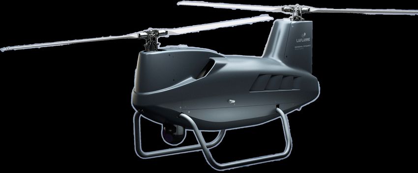
5.3 LX300 Turbo-Diesel . . . . . . . . . . . . . . . . . . . . . . . . . . . . . . . 32
5.4 Charge utile - Endurance optimale du LX300 Turbo-Diesel . . . . . . . . . 33
5.5 Charge utile - Portée optimale du LX300 Turbo-Diesel . . . . . . . . . . . 34
5.6 Contributions à la diminution de la consommation de carburant . . . . . . 34
5.7 Gains en endurance pour moteurs à étincelle et compression . . . . . . . . 36
5.8 Gains en portée pour moteurs à étincelle et compression . . . . . . . . . . 36
viiviii LISTE DES FIGURES
LISTE DES TABLEAUX

 4.1   Laflamme LX300-FTV Rotorcraft Characteristics1 . . . . . . . . . . . . . .       14

 5.1   Spécifications du Rotax 912iS Sport et du Continental CD-155 . . . . . . .       29
 5.2   Spécifications des différentes configurations du LX300 . . . . . . . . . . . .   30

                                           ix
x LISTE DES TABLEAUX
CHAPITRE 1

INTRODUCTION

L’augmentation rapide de la puissance de calcul et de sa disponibilité a permis l’apparition
d’aéronefs sans pilotes de plus en plus sophistiqués et capables d’accomplir des missions
complexes. L’utilisation d’aéronefs sans pilotes apporte nombreux avantages, les deux plus
important sont sans doute l’augmentation de la charge utile et l’élimination du danger pour
l’équipage. En effet, sans équipage à bord, la capacité de charge prise par celle-ci et les
composantes associées (sièges, tableau de bord, etc.) est maintenant disponible pour de la
charge utile ou du carburant supplémentaire. De plus, sans facteurs humains, les tâches
considérées dull, dirty and dangerous peuvent être accomplies sans soucis pour l’opérateur.

1.1      Mise en contexte et problématique
Un secteur qui voit beaucoup de potentiel pour les aéronefs autonomes est celui de la sur-
veillance maritime. Les commandants de navires ont un besoin primordial de savoir ce qui
se cache au-delà de l’horizon. De tous les types d’aéronef, ce sont les avions qui répondent
le mieux à ce besoin. Un avion possède des capacités d’endurance, de portée et d’altitude
supérieures à tout autre aéronef. Par contre, ces grandes capacités sont contraintes par
l’espace limitée des navires pour leur décollage et atterrissage. Les avions doivent donc
être déployés d’une base terrestre ou être miniaturisés pour être lancés à la main. Dans
les deux cas, leur portée est diminuée significativement. Un hélicoptère, malgré sa portée
moindre par rapport à un avion du même poids, est capable de décoller aisément depuis
un navire. Un hélicoptère autonome est donc un bon compromis entre performance et
capacité de déploiement depuis un navire.

Laflamme Aéro, une PME de la région de Chaudière-Appalaches, développe présentement
un drone hélicoptère et souhaite l’optimiser afin de répondre aux requis d’une mission de
surveillance maritime. Le LX300 (Fig. 1.1) est un drone hélicoptère tandem équipé de deux
rotors semi-rigides teetering et d’un moteur à combustion interne de 100 HP d’une capacité
de décollage de 300 kg. Il a été initialement développé dans le cadre du projet CARIC
AUT-703 faisant intervenir Laflamme Aéro, NGC Aérospatiale, RAAS, Sinters America,
Polytechnique Montréal et l’École de Technologie Supérieure [1, 2]. Le projet a résulté en
un véhicule instrumenté en condition de vol servant de démonstrateur technologique et de
plateforme d’essais.

                                             1
2 CHAPITRE 1. INTRODUCTION
En mai 2019, le projet CRIAQ UAS MaSu a officiellement été lancé regroupant Laflamme
Aéro, NGC Aérospatiale, l’École de Technologie Supérieure et l’Université de Sherbrooke.
Ce projet vise à développer des solutions pour répondre aux besoins du domaine maritime.
Figure 1.1 LX300 de Laflamme Aéro
Le milieu maritime impose certaines contraintes telle que l’utilisation de carburant lourd
et la capacité d’atterrir sur un navire en mer. Ces contraintes limites présentement la
compétition dans ce secteur d’opération et Laflamme compte y faire sa place.
Afin de bien remplir les requis d’une mission de surveillance maritime, le LX300 doit
pouvoir accomplir des vols de longue durée. En se basant sur les spécifications publiques de
Laflamme Aéro [3], on estime qu’à premier ordre, une réduction de 10% de la consommation
de carburant du véhicule résulterait en 53 minutes additionnelles de vol (éqn. 1.1). À des
fins de comparaison, le CH-148 Cyclone, l’hélicoptère présentement utilisé par la Marine
royale canadienne sur leurs frégates, a un requis d’endurance inférieur à trois heures [4].
Il y a donc un potentiel significatif d’améliorer l’endurance du LX300 de Laflamme Aéro
en réduisant sa consommation de carburant en cours d’opération.
Gain en endurance si la consommation est réduite de 10% a b
Qté. carburant [L] 138
Endurance = = = 8 [h]
Consommation moy. [L/h] 17.25
Qté. carburant [L] 138
Endurance′ = = = 8.888 [h]
90⁄100 · Consommation moy. [L/h] 0.9 · 17.25
∆Endurance = Endurance′ − Endurance = 53 [min] (1.1)
a. Qté. de carburant maximale : 100 kg de carburant Avgas (0.721 kg/L).
b. Consommation moyenne : calculée depuis l’endurance maximale de 8 h.1.2. PLAN DU DOCUMENT 3 1.2 Plan du document Ce mémoire débute en présentant l’état de l’art sur un concept prometteur pour diminuer la consommation de carburant d’hélicoptères. Ensuite, une majeure partie du contenu est présentée sous la forme d’un article soumis au Journal of the American Helicopter Society. Cet article contient une brève revue de littérature, suivie d’une présentation des modèles numériques et de la stratégie d’optimisation choisie. Ensuite, les résultats sont présentés suivis d’une discussion. L’article présente l’application du concept choisis sur le LX300 d’origine, soit celui pré- senté dans la mise en contexte. Toutefois, au cours du projet de recherche, le LX300 a subit un re-dimensionnement majeur, incluant l’intégration d’un moteur turbo-diesel qui était confidentiel lors de la rédaction de l’article. Ce mémoire contient donc un chapitre additionnel pour présenter les résultats de la stratégie sur la nouvelle configuration du LX300 équipée d’un moteur turbo-diesel et compare les bénéfices encourus.
4 CHAPITRE 1. INTRODUCTION
CHAPITRE 2

ÉTAT DE L’ART

Un calcul rapide d’ordre de grandeur (éqn. 1.1) révèle qu’une réduction de 10% de la
consommation moyenne du LX300 pourrait résultée en près d’une heure de vol supplémen-
taire. Puisque la consommation de carburant est étroitement liée à la puissance requise
(ṁ f = P · SFC ), si l’on suppose une efficacité constante, une diminution de 10% de la
consommation requiert une diminution équivalente de la puissance requise pour maintenir
l’hélicoptère en vol.

Une approche auparavant étudiée est le concept du slowed rotor aussi nommé variable
speed rotor (VSR), soit un rotor à vitesse variable [5]. Le concept est essentiellement le
suivant : en réduisant la vitesse de rotation d’un rotor en fonction de ses conditions de
vol, il peut opérer continuellement près de son point de plus haute efficacité. Il en découle
ainsi une diminution de la puissance requise pour maintenir l’hélicoptère en vol.

Le concept été sujet de plusieurs études l’appliquant à des modèles numériques du UH-60A
Black Hawk de Sikorsky [6, 7, 8, 9]. Ces études ont démontrées qu’une diminution de la
vitesse du rotor en vol de croisière permet une réduction de la puissance requise de 17%.
Il est montré que la demande en puissance due à la trainée parasite des pales est la source
principale de cette économie. À basse vitesse, le concept n’est donc pas aussi efficace dû
au fait que la majorité de la demande en puissance provient de la vitesse induite et celle-ci
n’est pas autant sensible à la vitesse du rotor. Le principal facteur limitant la diminution
en puissance est l’apparition du décrochage des pales en fonction de la vitesse, altitude
et masse de l’hélicoptère. En fait, si l’objectif était plutôt d’élargir l’enveloppe de vol de
l’hélicoptère, augmenter la vitesse du rotor permettrait à celui-ci d’opérer hors de la région
de décrochage plus longtemps et ainsi atteindre de plus grandes vitesses.

Les études ci-haut indiquent qu’il y a bien un potentiel de gain en performance en vol
stationnaire, d’endurance, de croisière (portée) ou à haute vitesse en variant la vitesse
d’un rotor. Toutefois, l’endurance et la portée dépendent de l’efficacité du moteur, qui
n’est pas réellement constante. Un ralentissement de la vitesse de rotation d’une turbine
à gaz, tel qu’installé sur le UH-60A, résulte en une perte d’efficacité importante [10]. La
diminution en puissance requise ne résulte donc pas nécessairement en une diminution
équivalente de la consommation de carburant, puisque ce sont des effets conflictuels.

                                              5
6 CHAPITRE 2. ÉTAT DE L’ART Garavello et Benini [11] ont publiés une étude préliminaire sur les impacts du slowed rotor sur un hélicoptère (UH-60A) couplé à un turboshaft (GE-T700). Leurs résultats ont démontrés que malgré la diminution en puissance requise, la consommation de carburant a augmentée en vol stationnaire et à haute vitesse due à la perte d’efficacité de la turbine à gaz. Toutefois une économie de carburant de 8-9% fut réalisée à des vitesses d’endurance. Misté et al. [12] ont eux aussi démontré l’importance de modéliser l’unité de puissance pour bien évaluer les gains en performance. Leur travail a démontré une économie de carburant de 7-8% pour une diminution du RPM de 15% sur le même hélicoptère et moteur que mentionné précédemment. Ils en concluent que malgré les contraintes d’opération de la turbine à gaz, le concept de slowed rotor est employable et que le développement d’une turbine à gaz ayant plus de latitude concernant sa vitesse d’opération permettrait d’exploiter le plein potentiel du concept. Goulos et Bonesso [13] ont étudié l’impact du type de mission sur les gains en performance. Leur étude démontre que le type de mission est un facteur principal sur les bénéfices du rotor à vitesse variable. Les plus grands gains en performance sont associées aux missions se déroulant à des vitesses d’endurance à basse altitude et à faible poids, tel que des missions de surveillance où une diminution de la consommation de carburant de 5% a été réalisée. Malgré les pertes d’efficacité des turbines à gaz en opération off-design, il est démontré qu’une diminution de la consommation de carburant est possible pour des vols d’endurance. En effet, lorsque qu’on considère la chute d’efficacité associée à la turbine et la demande en puissance variable durant une mission, les gains en performance passent de 17% de réduction de la puissance requise à 5% de réduction de la consommation. Cette diminution est équivalente à seulement 25 minutes de vol supplémentaires pour le LX300 de Laflamme, ce qui correspond à moins de la moitié de la valeur estimée initialement (éqn. 1.1). Toutefois, le LX300 de Laflamme Aéro n’est pas équipé d’une turbine à gaz, mais plutôt d’un moteur à allumage commandé, le Rotax 912iS Sport. Ce type de moteur bénéficie d’un gain d’efficacité lorsque sa vitesse est réduite à plus bas requis de puissance [14] à l’opposé de la turbine à gaz. De plus, dans le cadre du projet MaSu, Laflamme compte intégrer un moteur turbo-diesel capable de brûler du carburant lourd, le Continental CD-155. Les moteurs à allumage par compression (diesel) ont tendance à offrir une meilleure efficacité à bas régime que les moteurs à étincelle [14]. Le ralentissement du rotor diminuerait donc non seulement la puissance requise, mais aussi la consommation spécifique du moteur, résultant en un gain en endurance plus important. Cette combinaison du concept de rotor à vitesse variable et d’un moteur à piston n’est pas adressée dans la littérature.
CHAPITRE 3
QUESTION DE RECHERCHE

La synthèse de l’état de l’art a permis d’identifier que le concept du rotor à vitesse variable
a le potentiel d’améliorer la performance en vol d’endurance du LX300 sans avoir un
impact négatif sur ses autres capacités. Toutefois, les études actuelles sont limitées à des
hélicoptères conventionnels couplés à des turbines à gaz, qui réduisent les bénéfices de ce
concept, et négligent le cas des moteurs à allumage par étincelle ou compression.

De ce constat découle la question de recherche suivante :

                                 Question de recherche
        Quels bénéfices peut-on tirer du concept du rotor à vitesse variable pour
           un hélicoptère tandem couplé à un moteur à combustion interne à
         allumage par étincelle ou compression lorsque soumis aux contraintes
                        d’une mission de surveillance maritime ?

3.1      Objectifs du projet de recherche
Afin de répondre à cette question, l’objectif principal peut être défini comme suit :

                            Objectif du projet de recherche
          Développer un environnement numérique de simulation d’hélicoptère
          tandem équipé d’un moteur à combustion interne afin d’évaluer son
        enveloppe de vol, l’optimiser afin d’accomplir une mission de surveillance
                     maritime et quantifier les bénéfices engendrés.

Pour atteindre cet objectif, les sous-objectifs suivants doivent être atteints :
  1. Modéliser numériquement un hélicoptère tandem avec rotors teetering.
  2. Intégrer les cartes de performance des moteurs fournies par les manufacturiers.
     – Rotax 912 iS Sport.
     – Continental CD-155.
  3. Valider les modèles à l’aide de données acquises en vol stationnaire et basse vitesse.
  4. Développer un outil d’analyse de mission de vol.
  5. Optimiser la performance de l’hélicoptère lors d’une mission d’endurance.

                                              7
8 CHAPITRE 3. QUESTION DE RECHERCHE 3.2 Contributions originales Les résultats du projet de recherche présentés dans ce mémoire permettent d’établir le po- tentiel du concept de rotor à vitesse variable lorsque couplé avec un moteur à piston. Ces gains importants en autonomie et en distance franchissable pourrait permettre d’augmen- ter l’utilisation d’hélicoptères autonomes non seulement dans le milieu de la surveillance maritime, mais aussi dans des opérations de transport de charge sur longue distance.
CHAPITRE 4
MODÈLES, OPTIMISATION ET RÉSULTATS

Avant-propos
 Auteurs et affiliation :
  M. Bouchard : étudiant à la maîtrise, Université de Sherbrooke, Faculté de génie,
  Département de génie mécanique.
   D. Rancourt : professeur, Université de Sherbrooke, Faculté de génie, Département
   de génie mécanique.
   D. Laflamme : cofondateur et vice-président ingénierie, Laflamme Aéro Inc.
   E. Laflamme : cofondateur et président, Laflamme Aéro Inc.
 Date de soumission : 12 novembre 2020
 Revue : Journal of the American Helicopter Society
 Titre anglais : Endurance Optimization of a Tandem Helicopter with Variable Speed
   Rotors and a Spark-Ignition Engine.
 Titre français : Optimisation de l’endurance d’un hélicoptère tandem équipé de ro-
   tors à vitesse variable et d’un moteur à allumage par étincelle.
 Contribution au mémoire :
  Cet article représente la majeure partie du contenu de ce mémoire. Il présente le mo-
  dèle numérique d’hélicoptère tandem, le modèle du moteur à allumage commandé
  (Rotax 912iS Sport) et la validation expérimentale de ceux-ci. L’approche d’optimi-
  sation y est présentée. Les résultats montrent les gains possibles en endurance en
  utilisant l’approche des rotors variables couplée à un moteur à allumage commandé.
  L’évaluation des bénéfices de l’intégration d’un moteur à allumage par compression
  (Continental CD-155) est présentée au chapitre suivant.

                                         9
10 CHAPITRE 4. MODÈLES, OPTIMISATION ET RÉSULTATS
Résumé français :
L’utilisation d’hélicoptères non-pilotés devient une solution commune pour les acti-
vités de surveillance maritime dû aux bénéfices du décollage et atterrissage vertical.
L’augmentation de la durée de vol est donc cruciale ; une approche est de réduire la
vitesse des rotors en vol, ce qui améliore leur efficacité. Un modèle de performance
est utilisé pour évaluer les bénéfices des rotors à vitesse variable en vol d’endurance
lorsque couplé à un moteur à allumage commandé. Le modèle de performance est
validé en utilisant des données expérimentales de vols stationnaires et à basse vitesse.
Une approche d’optimisation par méta-modèle permet de déterminer les vitesses op-
timales de vol et des rotors pour minimiser la consommation de carburant au cours
d’une mission nominale d’endurance. Des courbes de charge utile versus endurance
et portée à différentes capacités de carburant démontrent les gains engendrés. Une
augmentation de l’endurance de 25% et 15% ont été possibles pour des vols à ca-
pacité de carburant standard et maximale, respectivement. La portée n’a pas été
impacté négativement, et voit plutôt une augmentation pour un vol à pleine capa-
cité de carburant. Le moteur à allumage par étincelle joue un rôle bénéfique en étant
responsable de jusqu’à 38% de la diminution de la consommation de carburant.
Résumé anglais :
Rotary unmanned aerial vehicles (R-UAV) are becoming commonplace as a solution
for maritime surveillance activities due to their vertical take-off and landing (VTOL)
capability. Extending flight duration is thus crucial ; one approach is to slow down
the rotors in flight, which improves their efficiency. An in-house tandem rotorcraft
performance model is used to evaluate the benefits of slowed rotors in endurance
flight when used in conjunction with a spark-ignition engine. The performance mo-
del is validated using experimental data from flight tests in hover and low-speed
flight. A surrogate-based optimization approach determines the flight and engine
speeds required for minimal fuel consumption throughout a typical endurance mis-
sion. Payload-Endurance and Payload-Range curves for flights at various payload
and fuel capacities show overall benefits. Gains up to 25% and 15% in endurance are
possible for flights at standard and maximum fuel capacity. Range is not impacted
negatively and sees gains at maximum fuel capacity. The spark-ignition engine plays
a beneficial role as it contributes up to 38% of fuel burn reduction.4.1. INTRODUCTION 11 4.1 Introduction The development and use of unmanned aerial vehicles (UAV) for maritime surveillance ap- plications have been on-going for over two decades [15]. Their ability to extend situational awareness beyond visual line of sight without compromising the safety of helicopters and their crew is a crucial advantage. While traditional winged UAVs offer great range and endurance characteristics, take-off and landing constraints of ships limit their usage. Un- manned rotorcraft, however, offer the capability of vertical take-off and landing combined with the capacity of hovering and low-speed loitering, making it an advantageous choice. Improving the performance of these rotary UAVs in endurance flight without necessarily penalizing hover or high-speed performance is thus of key interest. One such way to improve rotorcraft endurance flight is by slowing down its rotors in flight. The concept of the variable speed rotor (VSR) is, in principle, straightforward. By varying rotor speed in function of flight conditions, the rotor may operate as close as possible to its maximum equivalent lift-to-drag ratio, therefore reducing rotor power requirements and improving performance [5]. Studies conducted by Steiner, Mistry and Gandhi, Bowen- Davies and Chopra, as well as Han et al. [6, 7, 8, 9] using numerical models of the UH-60A Black Hawk helicopter demonstrated the effectiveness of the concept. A reduction of rotor RPM in cruise flight can lead up to a 17% decrease in power. At lower speeds, the concept is not as effective due to induced power being more important and less affected by rotor speed than profile power. The most significant limiting factor of the concept is the onset of stall, which limits the reduction of rotor RPM at high speed, altitude, and gross weight. In fact, the rotorcraft’s flight envelope can be extended by increasing rotor speed, therefore allowing the rotor to operate out of the stall region. The aforementioned articles indicate that a possible performance gain can be achieved in hover, loiter (endurance), cruise (range), and maximum speed. However, loiter and cruise performance depend entirely on the rotorcraft’s fuel consumption, which was not taken into account. The vast majority of current rotorcraft are powered by turboshaft engines, which are designed to operate at near-constant RPM. Garavello and Benini [11] conducted a preliminary study on the coupling of a slowed rotor (UH-60A) with a turboshaft engine (GE-T700). Their results showed that while power demand diminished when reducing rotor RPM, fuel consumption increased due to the turbine’s efficiency losses at off-design speeds, canceling out almost all benefits of a variable speed rotor. In fact, fuel burn increased in hover and high-speed flight. Nonetheless, fuel savings up to 8-9% were achieved at endurance speeds. Misté et al. [12] developed a methodology to determine the optimal speed of a rotor coupled to a turboshaft engine. Like Garavello and Benini [11], their work
12                       CHAPITRE 4. MODÈLES, OPTIMISATION ET RÉSULTATS

showed that minimizing rotor power requirements is not equivalent to minimizing fuel
consumption. Therefore, it is important to model the rotorcraft powerplant if endurance
is to be optimized. Simulations of the same rotorcraft used in the previously mentioned
studies resulted in a 7-8% reduction in fuel burn while limited to a 15% RPM decrease due
to the powerplant design. They concluded that the gas turbine’s limited RPM operating
range, while constraining, still enables the use of a variable speed rotor, and increasing
the range of allowable engine speed would allow unlocking more of the VSR’s potential.

Goulos and Bonesso [13] recently assessed the potential improvements at the mission le-
vel using a comprehensive rotorcraft model, including engine performance. Their results
showed that the type of mission being conducted is an essential factor in the effectiveness
of the variable speed rotor. The most significant performance improvements are associa-
ted with endurance-type missions with low gross weight and density altitude, such as
surveillance operations where up to a 5% decrease in fuel consumption is expected. It is
important to note that while some of the studies quantified potential fuel savings, only
Goulos and Bonesso took into account the decreasing weight of the helicopter as fuel is
burned, thus reducing power requirements over time.

This technology has been flight-tested on Boeing’s A160T Hummingbird, a turboshaft-
powered unmanned rotorcraft, which demonstrated benefits in endurance, range, altitude
ceiling, and payload capacity [16].

Reciprocating engines tend to benefit from quasi-constant efficiency throughout their
RPM operating range [14]. The combination of a reciprocating engine with the slowed
rotor concept could thus allow unlocking most of the concept’s potential in reducing fuel
consumption and increase flight endurance.

This paper aims to maximize the performance of an unmanned tandem helicopter in
endurance flight by employing the concept of variable speed rotors combined with the
advantageous efficiency of a spark-ignition engine. An in-house rotorcraft performance
model was developed to predict power and trim requirements in level flight. The model was
then calibrated using experimental data from flight tests of the rotorcraft. An optimization
routine leveraging surrogate models and parallel processing was used to find the optimal
combination of flight and rotor speeds throughout a typical endurance mission profile while
taking into account weight reduction and center of mass displacement due to fuel burn.
4.2. LX300 UNMANNED ROTORCRAFT                                                          13

4.2      LX300 Unmanned Rotorcraft
The Laflamme LX300™ depicted in figure 4.1 is an autonomous tandem helicopter de-
veloped to tackle various missions from maritime surveillance to payload delivery. The
rotorcraft is being developed with assistance from Transport Canada for certification pur-
poses and in cooperation with General Dynamics Mission Systems. It has a maximum
take-off weight (MTOW) of 300 kg, classifying it as a NATO class II UAS (150-600 kg)
[17], similarly to the UMS SKELDAR® V-200 and Schiebel CAMCOPTER® S-100.

                      Figure 4.1 LX300-FTV (Flight Test Vehicle)

The LX300 is powered by Rotax® ’s 912iS Sport, a 100 hp fuel-injection four-stroke aviation
engine. Due to the rotorcraft’s low power requirements (i.e., under 200 kW), the use of an
internal combustion engine grants better efficiency throughout its operating range than
the equivalent gas turbine [10], making it a favorable choice for this class of UAS.

The rotorcraft is equipped with two teetering rotor assemblies designed to reduce vi-
brations typical of two-bladed rotors while minimizing weight and drag associated with
articulated hubs and a higher number of blades. The blades have a high lift-to-drag ratio
airfoil and are made out of composite materials.

Table 4.1 lists some of the rotorcraft’s main characteristics.
14 CHAPITRE 4. MODÈLES, OPTIMISATION ET RÉSULTATS
Tableau 4.1 Laflamme LX300-FTV Rotorcraft Characteristics1
Characteristic U.S. Customary Metric
Engine Rotax 912iS Sport
Engine Power 2
100 hp 73.5 kW
Max Take-Off Weight 660 lb 300 kg
Empty Weight 418 lb 190 kg
Maximum Payload Weight 198 lb 90 kg
Maximum Fuel Weight 220 lb 100 kg
Rotor Diameter 2x 9.2 ft 2x 2.8 m
Airframe Length 9.5 ft 2.9 m
Airframe Height 4.9 ft 1.5 m
Airframe Width 3.9 ft 1.2 m
1
Specifications from Laflamme Aero’s website. (accessed June 2020)
2
Maximum available power according to Rotax.
4.3 Performance Models
4.3.1 Tandem Helicopter
An in-house performance model was developed to predict the rotorcraft’s power and trim
requirements, evaluate performance trade-offs and optimize its capabilities. The model uses
a modular approach in order to facilitate an increase in fidelity when required. The model’s
parametric nature allows for quick comparison and optimization of various configurations
and operating conditions.
The rotorcraft is modeled as a rigid-body on which rotor loads, fuselage drag, and gravity
are applied. The trim routine consists of an interior-point algorithm minimizing the sum
of forces and moments at the center of mass by varying the following six inputs : collective
control (δc ), differential collective (δb ), lateral cyclic (δs ), differential lateral cyclic (δr ),
fuselage pitch (ΘF ), and fuselage roll (ΦF ). Longitudinal cyclic control (θ1s ) is scheduled
as a function of airspeed, as used on the CH-47B [18], to level the fuselage and reduce
rotor blow-back.
The rotor inflow is a first harmonic nonuniform linear model with Pitt & Peters’ coefficients
[19]. To account for the interference caused by the two rotors overlapping each other, an
approach similar to Boeing’s BHSimIMM is followed [18, 20]. A fraction of the front rotor’s
uniform inflow component (λov ) is added to the rear rotor’s own induced velocity, resulting
in higher torque and collective at the rear rotor [21]. The rear-on-front rotor influence is
neglected as it is considered less significant especially as forward speed increases.4.3. PERFORMANCE MODELS 15
For more flexibility, calibration factors are exposed to allow tuning the model with experi-
mental data. These factors consist of multipliers on uniform (λ0 ), longitudinal (λ1c ), and
lateral (λ1s ) components of the inflow distribution for both rotors, and a multiplier on the
front-on-rear interference (λov ).
Each rotor is modeled as two linearly twisted rigid blades of uniform mass distribution
with a central flapping hinge. Only the first harmonics of flapping motion are considered.
Airfoil aerodynamics are evaluated using Cl and Cd look-up tables, which contain static
stall characteristics. Aerodynamic loads of the blade elements are numerically integrated
from the root to the tip of each blade while also taking into account tip losses. The resulting
loads are then averaged over the azimuth to obtain the steady forces. Due to the teetering
design of the rotors, only the torques around the hub axes are transferred to the fuselage
[22].
The evaluation of rotor inflow, flapping and aerodynamic loads is solved using a relaxed
fixed-point iteration (FPI) scheme which outputs thrust (T) and torque (Q) as outlined
in figure 4.2.
(0)
CT β(ψ)(0) , λov θ(r , ψ) θ(r , ψ)
T,Q Relaxed FPI CT
Rotor Inflow λ(r , ψ) λ(r , ψ)
β(ψ) Rotor Motion β(ψ)
CT Rotor Loads
Figure 4.2 Rotor sub-module.
Fuselage aerodynamics are represented by a set of non-dimensional force and moment
coefficients, which vary in function of fuselage attitude. These coefficients were evaluated
by fitting results from computational fluid dynamics (CFD) simulations of the fuselage,
skids, and rotor heads at various attitudes.16 CHAPITRE 4. MODÈLES, OPTIMISATION ET RÉSULTATS
4.3.2 Spark-Ignition Engine
The rotorcraft’s powerplant is a horizontally opposed 100 hp fuel-injected four-stroke avia-
tion engine manufactured by Rotax.
The Rotax 912iS Sport automatically switches to a rich air-fuel mixture when a particular
throttle position is reached, permitting higher power delivery at the cost of higher fuel
consumption. Figure 4.3 shows this behavior as well as the drop in specific fuel consumption
at moderate engine speeds and power. SFC values are normalized with respect to the
maximum value due to the confidential nature of the underlying data.
Figure 4.3 Normalized specific fuel consumption
A black box meta-model [23] is used to represent the manufacturer-provided engine deck.
The meta-model is generated using the predictive modeling tool from JMP® , Version
14.2.0 by SAS Institute Inc. Quality of the model is ensured using a k -fold cross-validation
approach which consists of splitting the data into k equal subsets and using the remaining
k -1 sets to train the model. The process is repeated k times, with a different subset each
time. A separate set of data obtained from experimental tests is then used to evaluate the
model’s global accuracy by comparing actual outputs with the meta-model’s predictions.
The ensuing model replicates main power and fuel trends as a function of :
– Intake manifold air pressure.
– Engine speed.
– Altitude.
– ISA temperature offset.
– Air-Fuel mixture control (PWR/ECO mode).4.4. EXPERIMENTAL VALIDATION 17
To find the fuel consumption associated with the rotorcraft power requirements, the squa-
red error between required and available power is minimized using a golden-section search
method with manifold air pressure as the input variable.
4.4 Experimental Validation
The availability of a functional flight test vehicle allowed to compensate for the lower fide-
lity of the numerical model by calibrating its power and trim predictions with experimental
data using the correction factors mentioned previously.
Flight tests in hover and low-speed flight were carried out by a pilot controlling the aircraft
remotely. The tests were conducted at fixed altitude and speed, under the best atmosphe-
ric conditions possible, to reproduce the steady-state behavior of the aircraft using the
numerical model.
The on-board data acquisition system recorded rotorcraft attitude, speeds and accelera-
tions, rotor collective and cyclic inputs, and the engine’s speed, fuel consumption, and
operating conditions.
Figures 4.4 and 4.5 compare the calibrated model’s fuel consumption and collective diffe-
rential (δb ) predictions with flight test data in normalized form 1 .
Figure 4.4 Experimental fuel consumption.
1. Normalized airspeed does not correspond to advance ratio.18 CHAPITRE 4. MODÈLES, OPTIMISATION ET RÉSULTATS
Figure 4.5 Experimental collective differential.
The model’s predictions correlate well with the available flight test data. The current state
of experimental validation is considered sufficient for the scope of this paper, considering it
is a comparative study, and the values are all normalized. Further tests at intermediate to
high speeds and various gross weights are planned to expand the validated flight envelope.
4.5 Endurance Flight Optimization
A typical endurance mission profile is defined as follows :
1. Warm up at max. continuous power for 5 minutes.
2. Flight at best endurance speeds.
3. Landing with 10% fuel reserve.
The fuel required during take-off, climb to altitude, and descent to landing site phases
is considered small enough to be neglected for a comparative study between optimal and
nominal endurance missions.
To simulate the mission, the model is called at a fixed time interval where at each new
step (t + 1), the reduction in fuel level (mf ) and rotorcraft mass (m), as well as center
of mass displacement (∆CG ) due to fuel burn is evaluated. A two-variable single-objective
optimization problem is then solved using a surrogate-based approach [23] to find the
best combination of flight and rotor speeds (V , Ω) to minimize fuel consumption (m ̇ f ).
Once the optimal flight and rotor speeds are found, trim requirements (δ, ΦF , ΘF ) are
evaluated by executing the helicopter performance model with the previous timestep’s (t)
trim requirements as initial values, as illustrated in fig. 4.6. This loop is evaluated until
the landing condition is reached, i.e. only the 10% fuel reserve is left.4.6. RESULTS & DISCUSSION 19
Mission Analysis δ(t) , ΦF (t) , ΘF (t) , m(t) , ∆CG (t) V(t) , Ω(t) m(t) , ∆CG (t)
δ(t+1) , ΦF (t+1) , ΘF (t+1) , ṁ f ∗(t+1) Performance Model
∗
V(t+1) , Ω∗(t+1) ∗
V(t+1) , Ω∗(t+1) Optimization V,Ω
mˆ̇ f Surrogate Models
Figure 4.6 Endurance mission optimization process.
A surrogate-based approach was selected to reduce computation time during the optimi-
zation process. Two shallow artificial neural networks (ANN) were trained to approximate
power requirements as well as act as a trim constraint for the optimizer. The performance
model is executed at each timestep to provide access to internal rotor state variables which
are used for later investigation.
The optimization problem is solved using a sequential quadratic programming method
whose upper bounds are the previous timestep’s optimal engine speed and airspeed. It
is constrained to stay out of the rich air-fuel mixture regime of the engine, as previously
discussed, since it’s a high fuel consumption regime used when more power is required,
which goes against the stated goal of economizing fuel.
4.6 Results & Discussion
Simulations were run at standard atmospheric conditions for various payload weights, at
both standard and maximum fuel capacity, to assess the benefits of variable speed rotors
on a tandem helicopter powered by a spark-ignition engine and the effects of a high fuel
to total mass ratio. According to the specifications in table 4.1, the LX300™ rotorcraft has
an empty weight of 190 kg and a maximum take-off weight of 300 kg, which corresponds
to 20 kg of fuel with 90 kg of payload at standard fuel capacity, and 100 kg of fuel with
10 kg of payload at maximum fuel capacity.
The ensuing subsections discuss the performance gains obtained by executing the process
illustrated in figure 4.6, the optimal speed schedule and the resulting decrease in fuel
consumption, the gains in rotor efficiency and their effect on stall margin, as well as the
contribution of the spark-ignition engine in reducing fuel burn.20 CHAPITRE 4. MODÈLES, OPTIMISATION ET RÉSULTATS
4.6.1 Performance gains
To illustrate the performance gains in endurance flight, a set of payload-endurance and
payload-range curves are shown in figures 4.7 and 4.8 which compare the performance of
an optimal endurance flight with a nominal case at speeds for minimum fuel consumption
and nominal engine speed for both standard and maximum fuel capacity. Endurance and
range axes are normalized with regards to the nominal flight at standard fuel capacity
with no payload.
The highest gains are realized during flights with no payload. At standard fuel capacity, a
25% increase is achieved in flight time, while a 15% increase is achieved at maximum fuel
capacity. However, in actual flight time, the 15% increase corresponds to a flight three (3)
times longer than the 25% increase. This difference in endurance gain is, in part, explained
by the fact that there is an 80 kg difference in take-off weight between each configuration.
At full payload capacity, both missions have the same take-off weight. In that case, the
respective endurance gains for standard and maximum fuel capacity are 5% and 12%,
respectively. While both configurations have the same take-off weight, fuel accounts for
less than 7% of the total mass at standard fuel capacity while it accounts for 33% at
maximum fuel capacity.
Figure 4.7 Increase in flight endurance for standard and maximum fuel capacity
In terms of range, longer flight times lead to longer distances traveled. With no payload,
the corresponding gains in achievable range are 10% and 6% for standard and maximum
fuel capacity, respectively. However, at its maximum take-off weight, the gains reduce
to less than 1% and 5%. Although the increase in range is negligible at standard fuel
capacity, endurance optimization does not negatively impact mission radius. The gains in4.6. RESULTS & DISCUSSION 21
range being lower than the corresponding gains in endurance are partly due to the faster
loss of airspeed as fuel is burned to achieve better fuel consumption.
Figure 4.8 Increase in range for standard and maximum fuel capacity
The use of variable speed rotors with a spark-ignition engine has a positive outcome
in terms of endurance, with up to a 25% increase at standard fuel capacity and a 15%
increase at maximum fuel capacity. With regards to range, there are no adverse effects
when compared to nominal operation, and in some cases, non-negligible gains are made
(up to 10% and 6% for flights with no payload).
4.6.2 Optimal endurance flight
To investigate further into the performance gains, two flight conditions are selected ; flights
at standard and maximum fuel capacity, both at full payload capacity. Thus both flights
have the same take-off weight (300 kg) and initial power requirements. Since the center of
mass displacement is equivalent for both configurations, the optimal solution for standard
fuel capacity corresponds to a subset of the solution at maximum fuel capacity.
To achieve the aforementioned gains, engine speed is reduced throughout the entire flight
(fig. 4.9). For a flight at standard fuel capacity, the optimal RPM stays nearly constant
throughout the flight, decreasing from 96% to 94% of the nominal engine speed. However,
at maximum fuel capacity, optimal engine speed continues to decrease down to 80% of the
nominal value.
The mechanical impact of first slowing down the rotors to 96%Ω0 and then over time
down to 80%Ω0 is out of the scope of this paper, however crossing such a range of rotor
speeds requires careful evaluation of the effects on vibrations, as well as hub and blade
loads. Since part of the decrease happens slowly over the whole flight, particular attention22 CHAPITRE 4. MODÈLES, OPTIMISATION ET RÉSULTATS
should be given if rotor harmonics are excited, as not to operate for a significant amount
of time in those conditions.
A possible trade-off would be to slow down the rotors to a constant speed for the whole
flight, thus reducing fuel consumption without facing possible issues from further speed
reduction. This could work particularly well at standard fuel capacity, which only slows
down another 2%Ω0 after the initial decrease. However, the negative impact on endurance
gains at maximum fuel capacity would be more significant.
Figure 4.9 Optimal engine speed for a flight at full payload capacity
This reduction in rotor speed, and thus power requirements, results in a faster airspeed
decrease for minimum fuel consumption. Figure 4.10 shows that this reduction is equal to
an initial 4% reduction, followed by a further reduction over time of under 1% at standard
fuel capacity and 7% at maximum fuel capacity.
While airspeed decreases at a higher rate than nominal endurance flight, it is not significant
enough to affect range negatively, as seen in figure 4.8. One aspect to consider however, is
that while airspeed in optimal endurance flight is at it lowest 89%V0 , nominal speed also
reduces as fuel is burned. The end result is a total reduction down to 81% of the initial
endurance speed at nominal operation.
Figure 4.11 illustrates the resulting decrease in fuel consumption at full payload capacity.
For comparison, the nominal decrease in fuel consumption due to fuel burn is included. The
decrease due to gains in rotor efficiency corresponds to the reduction in fuel consumption
that stems from the diminished power requirements of the slowed rotors without conside-
ring the engine. The leftover portion is due to the gains in engine efficiency when reducing
engine speed.4.6. RESULTS & DISCUSSION 23
Figure 4.10 Optimal flight speed for a flight at full payload capacity
At standard fuel capacity, the total reduction in fuel consumption at the end of the flight
is 12%, of which 6% comes from the loss of fuel mass, 4% is attributable to the rotors,
and the leftover 2% is attributable to the engine. At maximum fuel capacity, the total
reduction at end of flight is 41%, of which 28% comes from mass loss, 8% from the rotors,
and 5% from the engine.
Figure 4.11 Total fuel burn reduction24 CHAPITRE 4. MODÈLES, OPTIMISATION ET RÉSULTATS
Throughout the flight, the main contributor to the reduction in fuel consumption is the
gain in rotor efficiency, as seen in figure 4.12 with up to 84% of the savings. However, the
engine’s contribution becomes more significant as time goes on, increasing from 16% to
38% of fuel burn reductions.
Figure 4.12 Engine contribution to fuel burn reduction
To achieve the aforementioned performance gains, a reduction in engine/rotor speed and
airspeed is required. The reduction in engine/rotor speed goes from an initial 96%Ω0 down
to 80%Ω0 , while airspeed is decreased from 96%V0 down to 89%V0 , which means a total
reduction down to 81% of initial V0 . The performance gains achieved are not only due to
more efficient rotor operation but also due to more efficient engine operation, which can
account for more than a third (38%) of the fuel consumption reductions.
4.6.3 Tandem rotors
Slowing down the rotors results in a fuel consumption decrease of up to 8% throughout
the flight. This reduction in rotor speed requires an increase in blade pitch to maintain
the required thrust, which increases the lift-to-drag ratio of most blade elements and, in
turn, decreases profile power, thus reducing fuel consumption.
Figure 4.13 shows airfoil efficiency normalized with regards to its maximum value (Cl /Cd )max
for both rotors at the rotor tip of the retreating side (ψ = 270°) of both rotors for both
nominal and optimal flight at maximum fuel capacity. The slight difference in efficiency
between both rotors is, in part, due to the rear rotor operating in the front rotor’s wake
leading to different control inputs (δb and δr ) and rotor state.4.6. RESULTS & DISCUSSION 25
Figure 4.13 Rotor efficiency (Cl /Cd ) at (r , ψ) = (R, 270°)
During endurance flight at nominal speeds, the rotor does not operate at its design point.
Airfoil efficiency reaches a maximum value of 75%(Cl /Cd )max at the beginning of the flight
and lowers to 49% as fuel is burned and collective input decreases to maintain level flight.
By slowing down the rotors, blade pitch increases and so does airfoil efficiency for both
rotors. Airfoil efficiency at the blade tip of the retreating side of both rotors increases
from 75% to around 92% at the beginning of flight and stays nearly constant for the whole
duration.
One of the negative impacts introduced by operating at rotor speeds lower than the design
point is the loss of stall margin. Operating too close to the rotor’s thrust boundary would
leave dangerously low tolerance to wind gusts and limit maneuvering capability. Dynamic
stall being out of the scope of this paper, it leaves static stall as a criterion to establish
stall margin. Nonetheless, since dynamic stall is usually encountered at higher angles of
attack, static stall serves as an acceptable conservative estimate.
Figure 4.14 shows the maximum value of local airfoil lift coefficient (Cl ) with regards to
its maximum static lift coefficient (Cl max ) for each rotor in nominal and optimal flight at
maximum fuel capacity.
During nominal flight, the rotors operate at no more than 39% of their total lift capacity
and see a decreasing trend down to 26% as blade loading reduces. However, during optimal
flight, the rotors operate at a near constant 56-59% of their maximum static lift capacity.
While stall margin is reduced, it should be more than enough for gust tolerance and
maneuvering capabilities.Vous pouvez aussi lire