Pressmaßtabellen Table of crimping diameters Tableau de sertissage
←
→
Transcription du contenu de la page
Si votre navigateur ne rend pas la page correctement, lisez s'il vous plaît le contenu de la page ci-dessous
… wir schaffen Verbindungen

Pressmaßtabellen
Table of crimping diameters
Tableau de sertissage

                                                          www.schmitter-hydraulik.de

Hydraulik      Niederdruck      Drucklufttechnik       Fahrzeugelektrik
Hydraulics     Low Pressure     Pneumatic Technology   Electrical Equipment for Vehicles
Hydrauliques   Basse pression   Technologie de l‘air   Electrique pour véhicles
Gewindetabelle Thread table Tableau de filetage
Metrische Gewindeanschlüsse (24° Konus) Schl.-Nr. Gewinde Außen-Ø Innen-Ø Rohranschluss (RA)
Key no. Thread Outer-Ø Inner-Ø Pipe joint (PJ)
Metrical thread connections (24° cone) Clé Pas Ø Extérieur Ø Intérieur Ø Ext du tube (RC)
keg. zyl. mm mm LL L S
con. cyl.
Filetage métrique (cône 24°)
19 M 6X1 6,00 4,92
20 M 8X1 8,00 6,92 4
DKOL/DKOS M 10X1 10,00 8,92 5;6
CEL/CES M 12X1 12,00 10,92 8
21 01 M 10X1 10,00 8,92
Dichtkegelanschlüsse DKOL/DKOS 24° mit
O-Ring und Überwurfmutter 22 02 M 12X1,5 12,00 10,38 6
23 03 M 14X1,5 14,00 12,38 8 6
Conical seal connection DKOL/DKOS 24°
with O-ring and union nut 24 04 M 16X1,5 16,00 14,38 10 8
25 05 M 18X1,5 18,00 16,38 12 10
Raccordement DKOL/DKOS 24°
Ecrou tournant & joint torique 26 06 M 20X1,5 20,00 18,38 12
27 07 M 22X1,5 22,00 20,38 15 14
28 08 M 24X1,5 24,00 22,38 16
29 09 M 26X1,5 26,00 24,38 18
10 M 27X2 27,00 24,84
11 M 30X1,5 30,00 28,38
Außengewinde CEL/CES 24° 12 M 30X2 30,00 27,84 22 20
metrisches Feingewinde, zylindrisch
13 M 33X2 33,00 30,84
Outer thread nipple CEL/CES 24° 15 M 36X2 36,00 33,84 28 25
metric fine thread, cylindrical
75 M 38X1,5 38,00 36,38
Filetage externe CEL/CES 24° 16 M 42X2 42,00 39,84 30
Pas fin métrique, cylindrique
76 M 45X1,5 45,00 43,38
78 M 45X2 45,00 42,84 35
17 M 48X2 48,00 45,84
77 M 52X1,5 52,00 50,38
M 52X2 52,00 49,84 42 38
BSP-Gewindeanschlüsse (60° Konus) Schl.-Nr. BSP-Gewinde Gangzahl Außen-Ø Innen-Ø
Key no. BSP Thread No. of threads Outer-Ø Inner-Ø
BSP thread connections (60° cone) Clé Pas BSP Nombre de filets Ø Extérieur Ø Intérieur
keg. zyl. mm mm
Raccord fileté BSP (cône 60°) con. cyl.
51 31 1/8" 28 9,73 8,57
52 32 1/4" 19 13,16 11,45
53 33 3/8" 19 16,66 14,95
54 34 1/2" 14 20,96 18,63
55 35 5/8" 14 22,91 20,59
56 36 3/4" 14 26,44 24,12
57 37 1" 11 33,25 30,29
58 38 1 1/4" 11 41,91 38,95
59 39 1 1/2" 11 47,80 44,85
61 1 3/4" 11 53,74 50,78
60 40 2" 11 59,62 56,66
80 63 2 1/2" 11 75,18 72,23
81 76 3" 11 87,88 84,93
77 3 1/2" 11 100,33 98,01
82 78 4" 11 113,03 110,07
NPT- sowie kegelige BSPT-Gewindeanschlüsse: Seite 8
NPT- as well as BSPT-threads: page 8
NPT - Identique que pas BSP : page 8
www.schmitter-hydraulik.de kontakt@schmitter-hydraulik.de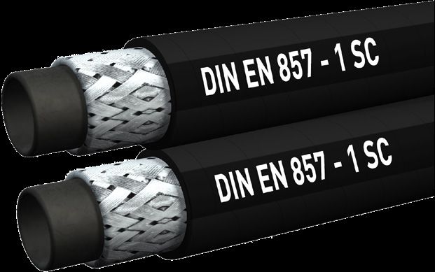
Gewindetabelle                                      Thread table                       Tableau de filetage

    JIC-Gewindeanschlüsse
    UN/UNF Gewinde mit 74° Außen-/Innenkonus                                Schl.-Nr. UN Gewinde       Außen-Ø     Innen-Ø     Bemerkung
                                                                            Key no.   UN thread        Outer-Ø     Inner-Ø     Note
                                                                            Clé       Pas UN           Ø Extérieur Ø Intérieur Remarque
    JIC thread connections
                                                                                                       mm            mm
    UN/UNF thread with 74° outer-/inner cone
                                                                            39         5/16"-24 UN     7,94          7,15      JIC
    Raccord fileté JIC                                                      40         3/8"-24 UNF     9,52          8,60      JIC
    Pas UN/UNF avec cône int/ext 74°
                                                                            41         7/16"-20 UNF 11,07            10,00     JIC + SAE
                                                                            42         1/2"-20 UNF     12,70         11,60     JIC + SAE
                                                                            43         9/16"-18 UNF 14,25            13,00     JIC + SAE
                                                                            71*        5/8"-18 UNF     15,85         14,70     SAE
                                                                            44         3/4"-16 UNF     19,00         17,60     JIC + SAE
                                                                            45         7/8"-14 UNF     22,17         20,50     JIC + SAE
                                                                            46         1 1/16"-12 UN 26,95           25,00     JIC
                                                                            72*        1 1/16"-14 UN 26,95           25,30     SAE
                                                                                       1 3/16"-12 UN 30,10           27,50     JIC + SAE
                                                                            47         1 5/16"-12 UN 33,30           31,30     JIC
                                                                            48         1 5/8"-12 UN    41,22         39,20     JIC
                                                                                       1 5/8"-14 UNS 41,22           39,50     PTT
                                                                            49         1 7/8"-12 UN    47,57         45,60     JIC
                                                                                       1 7/8"-14 UNS 47,57           45,90     PTT
                                                                            50         2 1/2"-12 UN    63,45         61,50     JIC + SAE
                                                                            51         3"-12 UN        76,20         74,30     JIC
                                                                                       3 1/2"-12 UN    88,90         87,00     JIC

    * = SAE-Gewindeanschlüsse 90° Außen-/Innenkonus
    * = SAE-thread connection 90° outer-/inner cone
    * = Raccord fileté SAE, cône int/ext 90°

    ORFS-Gewindeanschlüsse                                                 Schl.-Nr.   UN Gewinde      Außen-Ø       Innen-Ø     Bemerkung
    Flachabdichtung mit UN/UNF-Gewinde und stirnseitiger                   Key no.     UN thread       Outer-Ø       Inner-Ø     Note
    O-Ring-Abdichtung                                                      Clé         Pas UN          Ø Extérieur   Ø Intérieur Remarque
                                                                           ORS                         mm            mm
    ORFS thread connections                                                91          9/16"-18 UNF    14,25         13,00     ORS
    Flat face sealing with UN/UNF thread and O-ring seal on the end face   92          11/16"-16 UN    17,40         15,40     ORS
                                                                           93          13/16"-16 UN    20,50         18,60     ORS
    Raccord fileté ORFS
    Face plane, filet UN/UNF, étanchéité de surface par joint torique.     94          1"-14 UNS       25,30         23,10     ORS
                                                                           95          1 3/16"-12 UN   30,10         27,50     ORS
                                                                           96          1 7/16"-12 UN   36,40         33,80     ORS
                                                                           97          1 11/16"-12 UN 42,80          40,20     ORS
                                                                           98          2"-12 UN        50,70         48,10     ORS

www.schmitter-hydraulik.de                                                                               kontakt@schmitter-hydraulik.de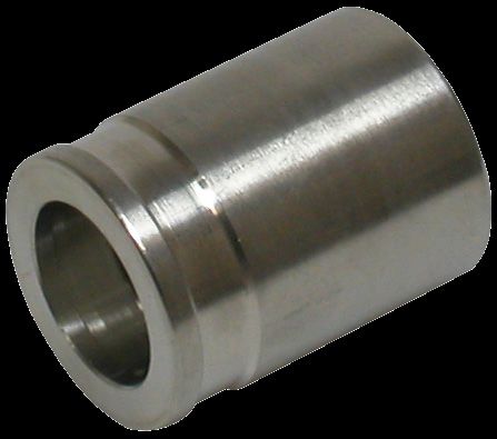
Gewindetabelle                              Thread table                   Tableau de filetage

    JIS - Gewindeanschlüsse
    BSP Gewinde mit 60° Außen-/Innenkonus

                                                                      Gewinde      Gangzahl         Außen-Ø            Innen-Ø
    JIS thread connections
                                                                      Thread       No. of threads   Outer-Ø            Inner-Ø
    BSP thread with 60° outer-/inner cone
                                                                      Pas          Nombre de filets Ø Extérieur        Ø Intérieur
                                                                                                    mm                 mm
    Raccord fileté JIS                                                1/4"         19                     13,16        11,45
    Pas BSP avec cône int/ext 60°
                                                                      3/8"         19                     16,66        14,95
                                                                      1/2"         14                     20,96        18,63
                                                                      3/4"         14                     26,44        24,12
                                                                      1"           11                     32,25        30,29
                                                                      1 1/4"       11                     41,91        38,95
                                                                      1 1/2"       11

    DKJ-Komatsu - Gewindeanschlüsse
    metrisches Gewinde mit 60° Außen-/Innenkonus

    DKJ-Komatsu - thread connections                                                   Gewinde      Außen-Ø         Innen-Ø
    Metrical thread with 60° outer-/inner cone                                         Thread       Outer-Ø         Inner-Ø
                                                                                       Pas          Ø Extérieur     Ø Intérieur
    Raccord fileté DKJ-Komatsu                                                                      mm              mm
    Pas métrique avec cône int/ext 60°
                                                                                       M 12X1,5     12,00           10,38
                                                                                       M 14X1,5     14,00           12,38
                                                                                       M 16X1,5     16,00           14,38
                                                                                       M 18X1,5     18,00           16,38
                                                                                       M 20X1,5     20,00           18,38
                                                                                       M 22X1,5     22,00           20,38
                                                                                       M 24X1,5     24,00           22,38
                                                                                       M 30X1,5     30,00           28,38
                                                                                       M 33X1,5     33,00           31,38
                                                                                       M 36X1,5     36,00           34,38
                                                                                       M 42X1,5     42,00           40,38

    Metrische Gewindeanschlüsse (24° Konus)
    französische Baureihe                                         Gewinde      Außen-Ø            Innen-Ø         Rohranschluss (RA)
                                                                  Thread       Outer-Ø            Inner-Ø         Pipe joint (PJ)
                                                                  Pas          Ø Extérieur        Ø Intérieur     Ø Ext du tube (RC)
    Metrical thread connections (24° cone)                                     mm                 mm                     F
    French series
                                                                  M 20x1,5     20,00              18,38                 13,25
    Pas métrique avec cône 24°                                    M 24X1,5     24,00              22,38                 16,75
    Série GAZ Française
                                                                  M 30X1,5     30,00              28,38                 21,25
                                                                  M 36X1,5     36,00              34,38                 26,75
                                                                  M 45X1,5     45,00              42,38                 33,50
                                                                  M 52X1,5     52,00              50,38                 42,25

www.schmitter-hydraulik.de                                                                   kontakt@schmitter-hydraulik.de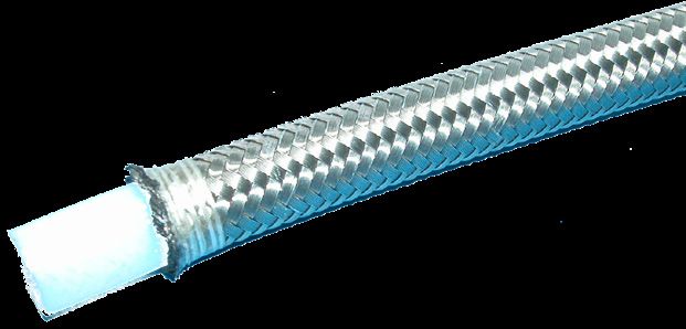
Gewindetabelle                        Thread table                  Tableau de filetage

    SFL 3000 PSI
    leichte Baureihe, SAE-Flanschanschluss
                                                            Flanschgröße    Flanschteller-Ø     Flanschtellerhöhe
                                                            Flange size     Flange plate Ø      Flange plate heigth
    SFL 3000 PSI                                            Taille          Ø de bride          Hauteur de bride
    Light series, SAE flange connection
                                                                            mm                  mm

    SFL 3000 PSI                                            1/2"            30,2                6,8
    Bride SAE série DIN légère
                                                            5/8"            34        Komatsu   6,8
                                                            3/4"            38,1                6,8
                                                            1"              44,5                8,0
                                                            1 1/4"          50,8                8,0
                                                            1 1/2"          60,3                8,0
                                                            2"              71,4                9,6
                                                            2 1/2"          84,1                9,6
                                                            3"              101,6               9,6

    SFS 6000 PSI
    schwere Baureihe, SAE-Flanschanschluss

    SFS 6000 PSI                                            Flanschgröße   Flanschteller-Ø      Flanschtellerhöhe
    Heavy series, SAE flange connection                     Flange size    Flange plate Ø       Flange plate heigth
                                                            Taille         Ø de bride           Hauteur de bride
    SFS 6000 PSI                                                           mm                   mm
    Bride SAE série DIN lourde
                                                            1/2"           31,7                 7,8
                                                            3/4"           41,3                 8,8
                                                            1"             47,6                 9,5
                                                            1 1/4"         54,0                 10,3
                                                            1 1/2"         63,5                 12,6
                                                            2"             79,4                 12,6

    SFS Supercat 9000 PSI
    schwere Baureihe, SAE-Flanschanschluss
    speziell Caterpillar
                                                            Flanschgröße   Flanschteller-Ø      Flanschtellerhöhe
                                                            Flange size    Flange plate Ø       Flange plate heigth
    SFS Supercat 9000 PSI                                   Taille         Ø de bride           Hauteur de bride
    Heavy series, SAE flange connection
    Especially Caterpillar                                                 mm                   mm

                                                            3/4"           41,3                 14,3
    SFS Supercat 9000 PSI
                                                            1"             47,6                 14,3
    Bride SAE Spéciale Caterpillar
                                                            1 1/4"         54,0                 14,3
                                                            1 1/2"         63,5                 14,3
                                                            2"             79,4                 14,3

www.schmitter-hydraulik.de                                                          kontakt@schmitter-hydraulik.de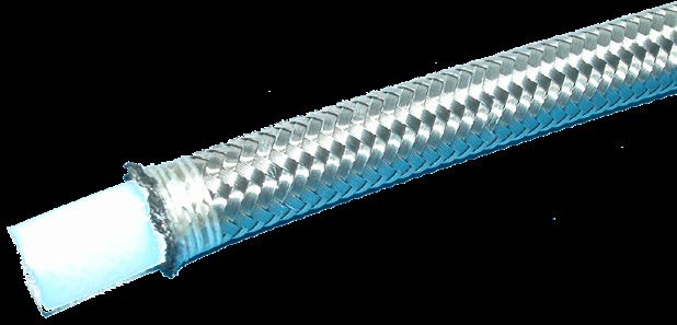
Gewindetabelle                                     Thread table                                   Tableau de filetage

    Hermetische Abdichtung bei kegeligen Gewinden
    Die kegeligen Gewinde schließen nicht hermetisch dicht. Um eine leckagesichere hermetische Abdichtung zu erzielen, müssen zusätzliche Dich-
    tungselemente eingefügt werden. Gut sind PTFE-Dichtungsbänder (z.B. TEFLON).

    Hermetic seal with tapered threads
    Tapered threads do not provide hermetic sealing. Additional sealing elements must be used to achieve leakage-proof hermetic sealing. PTFE sealing
    tape (for example, TEFLON) is good for such applications.

    Etancheité des filetages coniques
    Les filetages coniques ne sont pas étanches. Pour obtenir un montage hermétique, il est préconisé de rajouter d´autres éléments d´étanchéité. Les
    rubans d´étanchéité PTFE sont appropriés. (Ex: TEFLON)

             Einschraubgewinde Feingewinde
             Screw-in thread, fine thread
             Filetage mâle, pas fin

                                                                                                            Einschraubzapfen Form A
                Einschraubzapfen Form B                                                                     DIN 3852 Teil 2
                DIN 3852 Teil 1-2                                                                           Dichtung nach DIN 7603
                Abdichtung durch Dichtkante
                                                                                                            Screwed plug, Form A
                Screwed plug , Form B                                                                       DIN 3852, Part 2
                DIN 3852, Part 1-2                                                                          Sealing to DIN 7603
                Sealing by sealing edge
                                                                                                            Bouchon de Forme A
                Bouchon de Forme B                                                                          DIN 3852 Part 2
                DIN 3852 Part 1-2                                                                           Etanchéité selon DIN 7603
                Etanchéité par arrête

             Einschraubloch Form X
             DIN 3852 Teil 1-2
             (für zylindrische Einschraubzapfen)

             screw plug hole, Form X
             DIN 3852, Part 1-2
             (for cylindric screwed plug)

             Taraudage de Forme X
             DIN 3852 Part 1-2
             Pour bouchon vissé cylindrique

        Whitworth Rohrgewinde (BSPP), zylindrisch                                  metrisches Feingewinde, zylindrisch
        Whitworth pipe thread (BSPP), cylindric                                    Metric fine thread, cylindric
        Filetage Whitworth (BSPP), cylindrique                                     Filetage Métrique, cylindrique

                        +0,4                a1      b1                                            +0,4              a1       b1
             ØF                   ØN                          W                         ØF                 ØN                           W
                        Ø N1                max     max                                           Ø N1              max      max
           G 1/8"-28     15        14       1,0      8       0,1                     M 10X1,0      15       14       1,0       8        0,1
           G 1/4"-19     19        18       1,5     12       0,1                     M 12X1,5      18       17       1,5       12       0,1
           G 3/8"-19     23        22       2,0     12       0,1                     M 14X1,5      20       19       1,5       12       0,1
           G 1/2"-14     27        26       2,5     14       0,1                     M 16X1,5      22       21       1,5       12       0,1
           G 3/4"-14     33        32       2,5     16       0,2                     M 18X1,5      24       23       2,0       12       0,1
           G 1"-11       40        39       2,5     18       0,2                     M 20X1,5      26       25       2,0       14       0,1
          G 1 1/4"-11    50        49       2,5     20       0,2                     M 22X1,5      28       27       2,5       14       0,1
          G 1 1/2"-11    56        55       2,5     22       0,2                     M 26X1,5      32       31       2,5       16       0,2
                                                                                     M 27X2,0      33       32       2,5       16       0,2
                                                                                     M 33X2,0      40       39       2,5       18       0,2

         Toleranzklasse (A) gültig nur für Gewindezapfen                             M 42X2,0      50       49       2,5       20       0,2
         Tolerance class (A) current for male thread only                            M 48X2,0      56       55       2,5       22       0,2
         Tolérance classe (A,) valable pour filetage mâle uniquement

www.schmitter-hydraulik.de                                                                                       kontakt@schmitter-hydraulik.de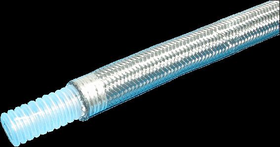
Gewindetabelle                                    Thread table                     Tableau de filetage

           Einschraubgewinde Feingewinde
           Screw-in thread, fine thread
           Filetage mâle, pas fin

           Einschraubzapfen Form E
           DIN 3852 Teil 11
           Dichtheit durch Dichtung

           Screwed plug, Form E
           DIN 3852, Part 11
           Sealing by washer seal

           Bouchon de Forme E
           DIN 3852 Part 11
           Etanchéité par joint

           Einschraubloch Form X
           DIN 3852 Teil 1-2
           (für zylindrische Einschraubzapfen)

           screw plug hole, Form X
           DIN 3852, Part 1-2
           (for cylindric screwed plug)

           Taraudage de Forme X
           DIN 3852 Part 1-2
           Pour bouchon vissé cylindrique

       Whitworth Rohrgewinde (BSPP), zylindrisch                     metrisches Feingewinde, zylindrisch
       Whitworth pipe thread (BSPP), cylindric                       Metric fine thread, cylindric
       Filetage Whitworth (BSPP), cylindrique                        Filetage Métrique, cylindrique

                     +0,4                 a1       b1                              +0,4              a1     b1
           ØF                   ØN                          W            ØF                  ØN                    W
                     Ø N1                 max      max                             Ø N1              max    max
          G 1/8"       15       13,9      1,0       8       0,1        M 10X1,0     15       13,9     1,0    8     0,1
          G 1/4"       20       18,9      1,5      12       0,1        M 12X1,5     18       16,9     1,5    12    0,1
          G 3/8"       23       21,9      2,0      12       0,1        M 14X1,5     20       18,9     1,5    12    0,1
          G 1/2"       28       26,9      2,5      14       0,1        M 16X1,5     23       21,9     1,5    12    0,1
          G 3/4"       33       31,9      2,5      16       0,2        M 18x1,5     25       23,9     2,0    12    0,1
           G 1"        41       39,9      2,5      18       0,2        M 20X1,5     27       25,9     2,0    14    0,1
         G 1 1/4"      51       49,9      2,5      20       0,2        M 22X1,5     28       26,9     2,5    14    0,1
         G 1 1/2"      56       54,9      2,5      22       0,2        M 26X1,5     33       31,9     2,5    16    0,2
                                                                       M 27X2,0     33       31,9     2,5    16    0,2
                                                                       M 33X2,0     41       39,9     2,5    18    0,2

       Toleranzklasse (A) gültig nur für Gewindezapfen                 M 42X2,0     51       49,9     2,5    20    0,2
       Tolerance class (A) current for male thread only                M 48X2,0     56       54,9     2,5    22    0,2
       Tolérance classe (A,) valable pour filetage mâle uniquement

www.schmitter-hydraulik.de                                                                          kontakt@schmitter-hydraulik.de
Gewindetabelle                                        Thread table                                  Tableau de filetage

           Einschraubgewinde Feingewinde
           Screw-in thread, fine thread
           Filetage mâle, pas fin

          Einschraubzapfen Form C                                                                            Einschraubzapfen NPT
          DIN 3852 Teil 1-2
          Abdichtung durch Kegelgewinde                                                                      Screwed plug NPT

          Screwed plug, Form C                                                                               Bouchon filetage NPT
          DIN 3852, Part 1-2
          Sealing by tapered thread

          Bouchon de Forme C
          DIN 3852 Part1-2
          Etanchéité par filetage conique

          Einschraubloch Form Z
          DIN 3852 Teil 1-2
          (für kegelige Einschraubzapfen)
                                                                                                             Einschraubloch NPT
          Port, Form Z
          DIN 3852, Part 1-2                                                                                 Screwed plug hole NPT
          (for tapered screwed plugs)
                                                                                                             Taraudage NPT
          Taraudage de Forme Z
          DIN 3852 Part 1-2
          Pour bouchon conique

       Whitworth Rohrgewinde (BSPT), kegelig                 metrisches Feingewinde, kegelig                 NPT Gewinde
       Whitworth pipe thread (BSPT), tapered                 Metric fine thread, tapered                     NPT thread
       Filetage Whitworth (BSPT), conique                    Filetage Métrique, conique                      Filetage NPT

                               b2                                                   b2                                               t3
                ØF                                                   Ø F1                                            NPT
                               min                                                  min                                              min
           R 1/8"-28 keg.       5,5                              M 8X1,0 kegelig     5,5                         1/8"-27,0 NPT       11,6
           R 1/4"-19 keg.       8,5                             M 10X1,0 kegelig     8,5                         1/4"-18,0 NPT       16,4
           R 3/8"-19 keg.       8,5                             M 12X1,5 kegelig     8,5                         3/8"-18,0 NPT       17,4
           R 1/2"-14 keg.      10,5                             M 14X1,5 kegelig    10,5                         1/2"-14,0 NPT       22,6
           R 3/4"-14 keg.      13,0                             M 16X1,5 kegelig    13,0                         3/4"-14,0 NPT       23,1
            R 1"-11 keg.       14,5                             M 18X1,5 kegelig    14,5                          1"-11,5 NPT        27,8
          R 1 1/4"-11 keg.     17,0                             M 20X1,5 kegelig    17,0                        1 1/4"-11,5 NPT      28,3
          R 1 1/2"-11 keg.     17,0                             M 22X1,5 kegelig    17,0                        1 1/2"-11,5 NPT      28,3

                                        Schl.-Nr.   NPT Gewinde      Gangzahl         Außen-Ø       Innen-Ø     Bemerkung
                                        Key no.     NPT thread       No. of threads   Outer-Ø       Inner-Ø     Note
                                        Clé         Pas NPT          Nombre de filets Ø Extérieur   Ø Intérieur Remarque
                                        NPT                                           mm            mm
                                        81          1/8"             27               9,70          8,60       NPT
                                        82          1/4"             18               13,10         11,30      NPT
                                        83          3/8"             18               16,30         15,10      NPT
                                        84          1/2"             14               20,20         18,60      NPT
                                        85          3/4"             14               25,50         24,10      NPT
                                        86          1"               11,5             32,20         30,20      NPT
                                        87          1 1/4"           11,5             41,00         38,90      NPT
                                        88          1 1/2"           11,5             47,00         44,90      NPT
                                        89          2"               11,5             58,90         56,70      NPT
                                        91          2 1/2"           8                72,69                    NPT
                                        93          3"               8                88,60                    NPT
                                        94          3 1/2"           8                101,31                   NPT
                                        95          4"               8                113,97                   NPT

www.schmitter-hydraulik.de                                                                                        kontakt@schmitter-hydraulik.de
Gewindetabelle                                 Thread table                    Tableau de filetage

           Einschraubgewinde Feingewinde
           Screw-in thread, fine thread
           Filetage pas fin

          Einschraubzapfen UNF-UN-2A
          mit O-Ring Dichtung (SAE J 514)

          Screwed plug, UNF-UN-2A
          with O-ring seal (SAE J 514)

          Bouchon UNF-UN-2A
          Etanchéité par joint torique (SAE J 514)

          Einschraubloch UNF-UN-2B
          mit O-Ring Dichtung (SAE J 514)

          UNF-UN-2B screwed plug hole
          with O-ring seal (SAE J 514)

          Taraudage UNF-UN-2B
          Avec joint torique (SAE J 514)

           UNF/UN-Gewinde
           UNF/UN thread
           Filetage UNF/UN

                                   b1        ØN      +0,1   +0,3   t1    ±1°   Ø N1   a1
                   UNF
                                   min       min      d2     t2    min    α    min    max
               7/16"-20 UNF         12       14,4    12,4   2,4    14    12°    21    1,0
               9/16"-18 UNF         13       17,6    15,6   2,5    16    12°    26    1,0
               3/4"-16 UNF          15       22,3    20,6   2,6    18    15°    32    1,5
               7/8"-14 UNF          17       25,5    23,9   2,6    20    15°    35    1,5
              1 1/16"-12 UNF        20       31,9    29,2   3,3    24    15°    42    1,5
              1 5/16"-12 UNF        20       38,2    35,5   3,3    24    15°    50    2,0
               1 5/8"-12 UNF        20       47,7    43,5   3,4    24    15°    60    2,5

www.schmitter-hydraulik.de                                                                  kontakt@schmitter-hydraulik.de
Anleitung für Prüfdorne
      Instruction for test mandrels
      Notice pour les piges de contrôle

    1. Wählen Sie den für Ihre Anforderungen benötigten Schlauch, sowie die dazu passenden Fassungen und Armaturen
    aus unserem Programm aus.

    2. Schneiden Sie den Schlauch mit einer entsprechenden Abschneidemaschine in die benötigte Länge.
    3. Falls das Schälen des Schlauches erforderlich ist, entfernen Sie den Obergummi (Schälmaße siehe Preßmaßtabelle),
    ohne dabei die Stahl-Spiralen des Schlauches zu beschädigen.
    4. Schieben Sie die Fassung komplett über den Schlauch und drücken Sie die Armatur vollständig in den Schlauch. Ver-
    wenden Sie einen Prüfdorn der entsprechenden Nennweite der Armatur und führen Sie diesen in die Armatur ein. Der
    Prüfdorn sollte vor dem Pressen bis zum Anschlag in die Armatur rutschen können. Ziehen Sie den Prüfdorn wieder
    aus dem Schlauch.

    5. Pressen Sie die Fassung lt. der Pressmaßtabelle, die Sie von uns erhalten können.
    6. Kontrollieren Sie das Pressmaß zuerst durch Messungen an der Außenseite der Fassung. Die Messungen sollten mit
    einer Toleranz von +0,0/-0,2mm den spezifischen Durchmesser entsprechen.
    7. Führen Sie nun wieder den Prüfdorn ein.
    8. Falls der NO-GO-Bereich des Prüfdornes, so wie im Bild unten zu sehen ist, stecken bleibt, ist das
    Pressmaß in Ordnung.
    9. Falls der NO-GO-Bereich des Prüfdornes sich weiterhin durch die Armatur schieben läßt, ist das Pressmaß in Schrit-
    ten von 0,1mm zu senken um eine optimale Nippeleinschnürung wie in der unteren Abbildung gezeigt.

www.schmitter-hydraulik.de                                                                  kontakt@schmitter-hydraulik.de
Anleitung für Prüfdorne
Instruction for test mandrels
Notice pour les piges de contrôle
1. Sélectionner le flexible adapté à vos exigences, ainsi que les douilles et embouts correspondants.
2. Découper le tuyau à sa longueur souhaitée avec une tronçonneuse adaptée.
3. S’il est nécessaire de dénuder le tuyau, retirez la surface supérieure de la robe (dimensions de dénudage, voir tab-
leau des côtes de sertissage) sans endommager les spirales en acier du tuyau.
4. Poussez la douille entièrement sur le tuyau et enfoncez l´embout à l´intérieur du tuyau. Utilisez un andrin d’essai de
la largeur nominale de l´embout et introduisez-le dans l´embout. Le mandrin d’essai doit glisser jusqu’à la butée de
l´embout avant le sertissage. Retirez le mandrin d’essai du tuyau.
5. Sertissez la douille selon le tableau des côtes de sertissage que vous pouvez recevoir de notre part.
6. Contrôlez les côtes de sertissage par mesure de la partie extérieure de la douille. Les côtes doivent correspondre à
une tolérance de +0,0/-0,2mm en respect du diamètre spécifique.
7. Introduisez à nouveau le mandrin d’essai.
8. Si la zone NO-GO de la pige de contrôle reste enfichée, comme dans l’illustration ci-dessous, la côte de sertissage
est correcte.
9. Si l’on peut continuer de déplacer la zone NO-GO du mandrin d’essai dans le embout, il faut réduire la côte de ser-
tissage par étapes de 0,1 mm pour un étranglement optimal de l´embout comme dans l’illustration ci-dessous.
1. Choose the right hose for your application, as well as the suitable ferrules and fittings out of our range of products.
2. Cut the hose with a special cutting machine into the needed length.
3. If needed, strip the cover of the hose ( for the strip dimensions look at the press dimensions schedule), without hur-
ting the steel wire spirals of the hose.
4. Move the ferrule complete on to the hose and push the fitting complete into the hose. Use a test pin for the right size
of the fitting and bring it into the fitting. The test pin should before crimping completely fit into the fitting. Pull the test
pin out of the hose.
5. Crimp the ferrule according to the press dimensions schedule, which is handed out from our company.
6. Controll the pressing dimensins first by measuring the outside dimensions of the ferrule. The measuring has to
comply with the specific diameter with a tolerance of +0,0/-0,2mm.
7. Now bring in the test pin again.
8. If the NO-GO-area of the test pin, as shown in the picture below, the pressing dimensions are all right.
9. If the NO-GO-area of the test pin still suits through the fitting, lower the pressing dimension in 0,1mm to reach an
optimal nipple throat as shown below.
www.schmitter-hydraulik.de kontakt@schmitter-hydraulik.dePressmaße für Schlauchtyp:
Crimping diameters for hose type: 1 TE
Cotes de sertissage pour tuyau de type:
424
Für Armaturen der Serie: Material: Stahl
For fittings of the series: Material: Steel
Pour embouts de la série: Matériaux: Acier
Oberdecke wird nicht entfernt
Fassung: DN 05-16 1 Riffelung mittig
DN 19-25 3 Rillen mittig
Cover won‘t be removed
Ferrule: DN 05-16 1 central riffle
DN 19-25 3 central grooves
Sans dénudage
Douille: DN 05-16 1 cannelure au milieu
DN 19-25 3 rainures au milieu
Schlauch Abmessungen Opt. Pressmaß Art.-Nr.
Hose Dimensions Opt. crimping diameter Item-No.
Tuyaux Dimensions Opt. diamètre de sertissage N° Art.
mm
DN Inch D L Ø/mm
05 3/16“ 15 26 13,0 423 41 05 01
06 1/4“ 17 29 14,9 423 41 06 01
08 5/16“ 20 30,5 16,7 423 41 08 01
10 3/8“ 22 32 18,5 423 41 10 01
12 1/2“ 27 32,5 22,6 423 41 12 01
16 5/8“ 31 37 26,6 423 41 16 01
19 3/4“ 36 43 31,9 423 43 20 01
25 1“ 44 49 39,1 423 43 25 01
Die angegebenen Pressmaße sind Richtwerte, die mit den Toleranzen der Schlauchdurchmesser und der Armaturen variieren. Art und Zustand der Presswerkzeuge haben maßgeb-
lichen Einfluss auf das Verpressergebnis.
Haftungs- und Gewährleistungsansprüche jeglicher Art sind ausgeschlossen. Änderungen vorbehalten!
The stated crimping measurements are guidelines, which will vary in size with the tolerances of the hose diameter and the fittings. The kind and the shape of the crimping tools have
significant influence to the crimping result.
Liability and warranty claims of all types are excluded. We reserve the right of error and technical modifications!
Les cotes de sertissage sont indiquées à titre indicatif. Elles varient selon les tolérances des diamètres des tuyaux et des embouts. L‘état et le type de presse ont une influence significa-
tive sur le sertissage.
Garantie et toute réclamation de toute nature sont exclues. Sous réserve de modifications!
www.schmitter-hydraulik.de Art.-Nr.: 999 423 001
kontakt@schmitter-hydraulik.de 11.2014Pressmaße für Schlauchtyp:
Crimping diameters for hose type: 2 TE
Cotes de sertissage pour tuyau de type:
424
Für Armaturen der Serie: Material: Stahl
For fittings of the series: Material: Steel
Pour embouts de la série: Matériaux: Acier
Oberdecke wird nicht entfernt
Fassung: DN 06-10 2 Riffelungen mittig
DN 12 1 Riffelung mittig
DN 16-25 1 Rille unten, oben abgesetzt
Cover won‘t be removed
Ferrule: DN 06-10 2 central riffles
DN 12 1 central riffle
DN 16-25 1 groove at the bottom, stepped at the top
Sans dénudage
Douille: DN 06-10 2 cannelures au milieu
DN 12 1 cannelure au milieu
DN 16-25 1 rainure en dessous, réduite en haut
Schlauch Abmessungen Opt. Pressmaß Art.-Nr.
Hose Dimensions Opt. crimping diameter Item-No.
Tuyaux Dimensions Opt. diamètre de sertissage N° Art.
mm
DN Inch D L Ø/mm
06 1/4“ 19 29 16,0 423 42 06 00
08 5/16“ 22 30 17,8 423 42 08 00
10 3/8“ 24 31 19,7 423 42 10 00
12 1/2“ 27 32,5 22,9 423 41 12 01
16 5/8“ 32 35 28,0 423 45 16 01
19 3/4“ 36 40 32,5 423 45 20 01
25 1“ 45 50 41,0 423 45 25 01
Die angegebenen Pressmaße sind Richtwerte, die mit den Toleranzen der Schlauchdurchmesser und der Armaturen variieren. Art und Zustand der Presswerkzeuge haben maßgeb-
lichen Einfluss auf das Verpressergebnis.
Haftungs- und Gewährleistungsansprüche jeglicher Art sind ausgeschlossen. Änderungen vorbehalten!
The stated crimping measurements are guidelines, which will vary in size with the tolerances of the hose diameter and the fittings. The kind and the shape of the crimping tools have
significant influence to the crimping result.
Liability and warranty claims of all types are excluded. We reserve the right of error and technical modifications!
Les cotes de sertissage sont indiquées à titre indicatif. Elles varient selon les tolérances des diamètres des tuyaux et des embouts. L‘état et le type de presse ont une influence significa-
tive sur le sertissage.
Garantie et toute réclamation de toute nature sont exclues. Sous réserve de modifications!
www.schmitter-hydraulik.de Art.-Nr.: 999 423 002
kontakt@schmitter-hydraulik.de 11.2014Pressmaße für Schlauchtyp:
Crimping diameters for hose type: 3 TE
Cotes de sertissage pour tuyau de type:
424
Für Armaturen der Serie: Material: Stahl
For fittings of the series: Material: Steel
Pour embouts de la série: Matériaux: Acier
Oberdecke wird nicht entfernt
Fassung: DN 06-31 2 Riffelungen mittig
DN 38-51 2 Rillen mittig
Cover won‘t be removed
Ferrule: DN 06-31 2 central riffles
DN 38-51 2 central grooves
Sans dénudage
Douille: DN 06-31 2 cannelures au milieu
DN 38-51 2 rainures au milieu
Schlauch Abmessungen Opt. Pressmaß Art.-Nr.
Hose Dimensions Opt. crimping diameter Item-No.
Tuyaux Dimensions Opt. diamètre de sertissage N° Art.
mm
DN Inch D L Ø/mm
06 1/4“ 19 29 17,2 423 42 06 00
08 5/16“ 22 30 19,5 423 42 08 00
10 3/8“ 24 31 21,4 423 42 10 00
12 1/2“ 28,5 34 24,5 423 42 12 00
16 5/8“ 32 36 28,7 423 42 16 00
19 3/4“ 38 42 33,6 423 42 20 00
25 1“ 46 50 42,0 423 42 25 00
31 1 1/4“ 52 57 47,0 423 42 32 00
38 1 1/2“ 62 60 56,0 423 44 40 01
51 2“ 75 75 69,0 423 44 50 01
Die angegebenen Pressmaße sind Richtwerte, die mit den Toleranzen der Schlauchdurchmesser und der Armaturen variieren. Art und Zustand der Presswerkzeuge haben maßgeb-
lichen Einfluss auf das Verpressergebnis.
Haftungs- und Gewährleistungsansprüche jeglicher Art sind ausgeschlossen. Änderungen vorbehalten!
The stated crimping measurements are guidelines, which will vary in size with the tolerances of the hose diameter and the fittings. The kind and the shape of the crimping tools have
significant influence to the crimping result.
Liability and warranty claims of all types are excluded. We reserve the right of error and technical modifications!
Les cotes de sertissage sont indiquées à titre indicatif. Elles varient selon les tolérances des diamètres des tuyaux et des embouts. L‘état et le type de presse ont une influence significa-
tive sur le sertissage.
Garantie et toute réclamation de toute nature sont exclues. Sous réserve de modifications!
www.schmitter-hydraulik.de Art.-Nr.: 999 423 003
kontakt@schmitter-hydraulik.de 11.2014Pressmaße für Schlauchtyp:
Crimping diameters for hose type: R4
Cotes de sertissage pour tuyau de type:
424
Für Armaturen der Serie: Material: Stahl
For fittings of the series: Material: Steel
Pour embouts de la série: Matériaux: Acier
Oberdecke wird nicht entfernt
Fassung: 4 Rillen mittig
Cover won‘t be removed
Ferrule: 4 central grooves
Sans dénudage
Douille: 4 rainures au milieue
Schlauch Abmessungen Opt. Pressmaß Art.-Nr.
Hose Dimensions Opt. crimping diameter Item-No.
Tuyaux Dimensions Opt. diamètre de sertissage N° Art.
mm
DN Inch D L Ø/mm
19 3/4“ 38 40 33,8 423 80 20 00
25 1“ 43 42 39,3 423 80 25 00
31 1 1/4“ 54 50 49,0 423 80 32 00
38 1 1/2“ 60 50 55,5 423 80 40 00
51 2“ 73 50,5 66,8 423 80 50 00
63 2 1/2“ 88 67 81,4 423 80 65 00
76 3“ 100 67 93,8 423 80 75 00
Die angegebenen Pressmaße sind Richtwerte, die mit den Toleranzen der Schlauchdurchmesser und der Armaturen variieren. Art und Zustand der Presswerkzeuge haben maßgeb-
lichen Einfluss auf das Verpressergebnis.
Haftungs- und Gewährleistungsansprüche jeglicher Art sind ausgeschlossen. Änderungen vorbehalten!
The stated crimping measurements are guidelines, which will vary in size with the tolerances of the hose diameter and the fittings. The kind and the shape of the crimping tools have
significant influence to the crimping result.
Liability and warranty claims of all types are excluded. We reserve the right of error and technical modifications!
Les cotes de sertissage sont indiquées à titre indicatif. Elles varient selon les tolérances des diamètres des tuyaux et des embouts. L‘état et le type de presse ont une influence significa-
tive sur le sertissage.
Garantie et toute réclamation de toute nature sont exclues. Sous réserve de modifications!
www.schmitter-hydraulik.de Art.-Nr.: 999 423 004
kontakt@schmitter-hydraulik.de 11.2014Pressmaße für Schlauchtyp:
Crimping diameters for hose type: 1 SN, 1 SN-HT
Cotes de sertissage pour tuyau de type:
424
Für Armaturen der Serie: Material: Stahl
For fittings of the series: Material: Steel
Pour embouts de la série: Matériaux: Acier
Oberdecke wird nicht entfernt
Fassung: DN 05-51 1 Rille unten, oben abgesetzt
Cover won‘t be removed
Ferrule: DN 05-51 1 groove at the bottom, stepped at the top
Sans dénudage
Douille: DN 05-51 1 rainure en dessous, réduite en haut
Schlauch Abmessungen Opt. Pressmaß Einschnürung Art.-Nr.
Hose Dimensions Opt. crimping diameter Constriction Item-No.
Tuyaux Dimensions Opt. diamètre de sertissage Rétrécissement N° Art.
mm Ø/mm
DN Inch D L Ø/mm max. min
05 3/16“ 19 24 15,2 2,65 2,85 423 45 05 01
06 1/4“ 20 27 16,1 3,65 3,85 423 45 06 01
08 5/16“ 22 27,5 17,8 5,1 5,3 423 45 08 01
10 3/8“ 24,5 30 20,3 6,3 6,5 423 45 10 01
12 1/2“ 28 32,5 23,6 8,6 9,0 423 45 12 01
16 5/8“ 32 35 27,2 11,2 11,7 423 45 16 01
19 3/4“ 36 40 31,4 13,6 14,1 423 45 20 01
25 1“ 45 50 39,2 19,0 19,5 423 45 25 01
31 1 1/4“ 54 50 46,8 24,9 25,4 423 45 32 01
38 1 1/2“ 62 55 53,9 30,8 31,3 423 45 40 01
51 2“ 76 60 67,2 42,5 43,0 423 45 50 01
Die angegebenen Pressmaße sind Richtwerte, die mit den Toleranzen der Schlauchdurchmesser und der Armaturen variieren. Art und Zustand der Presswerkzeuge haben maßgeb-
lichen Einfluss auf das Verpressergebnis. Die Prüfung der korrekten Verpressung ist nur durch Messung der erforderlichen Nippeleinschnürung möglich. Verwenden Sie hierzu unsere
Prüfdorne!
Haftungs- und Gewährleistungsansprüche jeglicher Art sind ausgeschlossen. Änderungen vorbehalten!
The stated crimping measurements are guidelines, which will vary in size with the tolerances of the hose diameter and the fittings. The kind and the shape of the crimping tools have
significant influence to the crimping result.The testing of the correct crimping is only possible with measuring the necking of the fitting. Use our test mandrels for it!
Liability and warranty claims of all types are excluded. We reserve the right of error and technical modifications!
Les cotes de sertissage sont indiquées à titre indicatif. Elles varient selon les tolérances des diamètres des tuyaux et des embouts. L‘état et le type de presse ont une influence significa-
tive sur le sertissage. La vérification du bon sertissage se fera par l‘emmanchement de la pige dans l‘embout requis. Pour cela, utilisez nos piges de contrôle sur l‘affaissement intérieur
de l‘embout!
Garantie et toute réclamation de toute nature sont exclues. Sous réserve de modifications!
www.schmitter-hydraulik.de Art.-Nr.: 999 423 005
kontakt@schmitter-hydraulik.de 09.2021Press- und Schälmaße für Schlauchtyp:
Crimping diameters and skiving lengths for hose type: 1 SN, 1 SN-HT
Cotes de sertissage et dénudage pour tuyau de type:
Für Armaturen der Serie:
For fittings of the series:
Pour embouts de la série: 424
Material: Stahl
Material: Steel
Matériaux: Acier
1 ST
Oberdecke muss entfernt werden
Fassung: DN 05-25 3 Rillen mittig
DN 31-51 1 Rille mittig
Cover has to be removed
Ferrule: DN 05-25 3 central grooves
DN 31-51 1 central groove
Dénuder la robe extérieure
Douille: DN 05-25 3 rainures au milieu
DN 31-51 1 rainure au milieu
Schlauch Abmessungen Schällänge außen Opt. Pressmaß Einschnürung Art.-Nr.
Hose Dimensions Outer skive length Opt. crimping diameter Constriction Item-No.
Tuyaux Dimensions Dénudage extérieur Opt. diamètre de sertissage Rétrécissement N° Art.
mm mm Ø/mm
DN Inch D L Ø/mm max. min
05 3/16“ 17 26 18 13,0 2,65 2,85 423 43 05 01
06 1/4“ 19 29 20 15,0 3,65 3,85 423 43 06 01
08 5/16“ 21 29 20 16,5 5,1 5,3 423 43 08 01
10 3/8“ 23 31,5 23 18,5 6,3 6,5 423 43 10 01
12 1/2“ 27 34 27 22,3 8,6 9,0 423 43 12 01
16 5/8“ 32 37 27 26,7 11,2 11,7 423 43 16 01
19 3/4“ 36 43 31 30,8 13,6 14,1 423 43 20 01
25 1“ 44 49 34 38,5 19,0 19,5 423 43 25 01
31 1 1/4“ 50 55 39 45,2 24,9 25,4 423 43 32 01
38 1 1/2“ 57 60 43 52,7 30,8 31,3 423 43 40 01
51 2“ 70 75 58 65,2 42,5 43 423 43 50 01
Die angegebenen Pressmaße sind Richtwerte, die mit den Toleranzen der Schlauchdurchmesser und der Armaturen variieren. Art und Zustand der Presswerkzeuge haben maßgeb-
lichen Einfluss auf das Verpressergebnis. Die Prüfung der korrekten Verpressung ist nur durch Messung der erforderlichen Nippeleinschnürung möglich. Verwenden Sie hierzu unsere
Prüfdorne! Bei der Montageanweisung -Geschält- sind die Schläuche bis zur Drahtlage zu schälen, die Drähte dürfen hierbei aber nicht beschädigt werden. Eine Restgummischicht von
0,2 bis 0,3 mm nach dem Schälen ist bei Geflechtschäuchen zulässig.
Haftungs- und Gewährleistungsansprüche jeglicher Art sind ausgeschlossen. Änderungen vorbehalten!
The stated crimping measurements are guidelines, which will vary in size with the tolerances of the hose diameter and the fittings. The kind and the shape of the crimping tools have
significant influence to the crimping result.The testing of the correct crimping is only possible with measuring the necking of the fitting. Use our test mandrels for it! At the installation
instruction, -Cover removed- the hoses have to be skived till to the wire position, but the wires must not be damaged. A remaining rubber layer of 0.2 till 0.3 mm, after skiving is valid for
steel wire hoses.
Liability and warranty claims of all types are excluded. We reserve the right of error and technical modifications!
Les cotes de sertissage sont indiquées à titre indicatif. Elles varient selon les tolérances des diamètres des tuyaux et des embouts. L‘état et le type de presse ont une influence significa-
tive sur le sertissage. La vérification du bon sertissage se fera par l‘emmanchement de la pige dans l‘embout requis. Pour cela, utilisez nos piges de contrôle sur l‘affaissement intérieur
de l‘embout! Instruction d‘assemblage et de montage pour l‘ensemble des tuyaux à dénuder : il est conseillé de dénuder jusque sur la tresse en métal mais sans endommager les fils.
Une couche de caoutchouc restante de 0,2 à 0,3 mm après le dénudage est autorisée sur un tuyau tressé.
Garantie et toute réclamation de toute nature sont exclues. Sous réserve de modifications!
www.schmitter-hydraulik.de Art.-Nr.: 999 423 006
kontakt@schmitter-hydraulik.de 11.2014Pressmaße für Schlauchtyp:
Crimping diameters for hose type: 2 SN
Cotes de sertissage pour tuyau de type:
424
Für Armaturen der Serie: Material: Stahl
For fittings of the series: Material: Steel
Pour embouts de la série: Matériaux: Acier
Oberdecke wird nicht entfernt
Fassung: 2 Rillen unten, oben abgesetzt
Cover won‘t be removed
Ferrule: 2 grooves at the bottom, stepped at the top
Sans dénudage
Douille: 2 rainures en dessous, réduite en haut
Schlauch Abmessungen Opt. Pressmaß Einschnürung Art.-Nr.
Hose Dimensions Opt. crimping diameter Constriction Item-No.
Tuyaux Dimensions Opt. diamètre de sertissage Rétrécissement N° Art.
mm Ø/mm
DN Inch D L Ø/mm max. min.
05 3/16“ 20 24 15,6 2,65 2,85 423 46 05 01
06 1/4“ 22 26 17,1 3,65 3,85 423 46 06 01
08 5/16“ 24 27,5 19,1 5,1 5,3 423 46 08 01
10 3/8“ 26 30 20,8 6,3 6,5 423 46 10 01
12 1/2“ 30 32,5 24,3 8,6 9,0 423 46 12 01
16 5/8“ 34 35 27,6 11,2 11,7 423 46 16 01
19 3/4“ 38 40 32,0 13,6 14,1 423 46 20 01
25 1“ 48 50 40,5 19,0 19,5 423 46 25 01
31 1 1/4“ 60 57 50,3 24,9 25,4 423 46 32 01
38 1 1/2“ 67 62 57,6 30,8 31,3 423 46 40 01
51 2“ 80 66 69,2 42,5 43,0 423 46 50 01
Die angegebenen Pressmaße sind Richtwerte, die mit den Toleranzen der Schlauchdurchmesser und der Armaturen variieren. Art und Zustand der Presswerkzeuge haben maßgeb-
lichen Einfluss auf das Verpressergebnis. Die Prüfung der korrekten Verpressung ist nur durch Messung der erforderlichen Nippeleinschnürung möglich. Verwenden Sie hierzu unsere
Prüfdorne!
Haftungs- und Gewährleistungsansprüche jeglicher Art sind ausgeschlossen. Änderungen vorbehalten!
The stated crimping measurements are guidelines, which will vary in size with the tolerances of the hose diameter and the fittings. The kind and the shape of the crimping tools have
significant influence to the crimping result.The testing of the correct crimping is only possible with measuring the necking of the fitting. Use our test mandrels for it!
Liability and warranty claims of all types are excluded. We reserve the right of error and technical modifications!
Les cotes de sertissage sont indiquées à titre indicatif. Elles varient selon les tolérances des diamètres des tuyaux et des embouts. L‘état et le type de presse ont une influence significa-
tive sur le sertissage. La vérification du bon sertissage se fera par l‘emmanchement de la pige dans l‘embout requis. Pour cela, utilisez nos piges de contrôle sur l‘affaissement intérieur
de l‘embout!
Garantie et toute réclamation de toute nature sont exclues. Sous réserve de modifications!
www.schmitter-hydraulik.de Art.-Nr.: 999 423 007
kontakt@schmitter-hydraulik.de 11.2014Pressmaße für Schlauchtyp:
Crimping diameters for hose type: 2 SN-HT
Cotes de sertissage pour tuyau de type:
424
Für Armaturen der Serie: Material: Stahl
For fittings of the series: Material: Steel
Pour embouts de la série: Matériaux: Acier
Oberdecke wird nicht entfernt
Fassung: 2 Rillen unten, oben abgesetzt
Cover won‘t be removed
Ferrule: 2 grooves at the bottom, stepped at the top
Sans dénudage
Douille: 2 rainures en dessous, réduite en haut
Schlauch Abmessungen Opt. Pressmaß Einschnürung Art.-Nr.
Hose Dimensions Opt. crimping diameter Constriction Item-No.
Tuyaux Dimensions Opt. diamètre de sertissage Rétrécissement N° Art.
mm Ø/mm
DN Inch D L Ø/mm max. min.
05 3/16“ 20 24 15,6 2,65 2,85 423 46 05 01
06 1/4“ 22 26 17,7 3,65 3,85 423 46 06 01
08 5/16“ 24 27,5 19,6 5,1 5,3 423 46 08 01
10 3/8“ 26 30 21,4 6,3 6,5 423 46 10 01
12 1/2“ 30 32,5 25,0 8,6 9,0 423 46 12 01
16 5/8“ 34 35 28,7 11,2 11,7 423 46 16 01
19 3/4“ 38 40 32,3 13,6 14,1 423 46 20 01
25 1“ 48 50 41,6 19,0 19,5 423 46 25 01
31 1 1/4“ 60 57 51,3 24,9 25,4 423 46 32 01
38 1 1/2“ 67 62 58,3 30,8 31,3 423 46 40 01
51 2“ 80 66 70,9 42,5 43,0 423 46 50 01
Die angegebenen Pressmaße sind Richtwerte, die mit den Toleranzen der Schlauchdurchmesser und der Armaturen variieren. Art und Zustand der Presswerkzeuge haben maßgeb-
lichen Einfluss auf das Verpressergebnis. Die Prüfung der korrekten Verpressung ist nur durch Messung der erforderlichen Nippeleinschnürung möglich. Verwenden Sie hierzu unsere
Prüfdorne!
Haftungs- und Gewährleistungsansprüche jeglicher Art sind ausgeschlossen. Änderungen vorbehalten!
The stated crimping measurements are guidelines, which will vary in size with the tolerances of the hose diameter and the fittings. The kind and the shape of the crimping tools have
significant influence to the crimping result.The testing of the correct crimping is only possible with measuring the necking of the fitting. Use our test mandrels for it!
Liability and warranty claims of all types are excluded. We reserve the right of error and technical modifications!
Les cotes de sertissage sont indiquées à titre indicatif. Elles varient selon les tolérances des diamètres des tuyaux et des embouts. L‘état et le type de presse ont une influence significa-
tive sur le sertissage. La vérification du bon sertissage se fera par l‘emmanchement de la pige dans l‘embout requis. Pour cela, utilisez nos piges de contrôle sur l‘affaissement intérieur
de l‘embout!
Garantie et toute réclamation de toute nature sont exclues. Sous réserve de modifications!
www.schmitter-hydraulik.de Art.-Nr.: 999 423 008
kontakt@schmitter-hydraulik.de 11.2014Pressmaße für Schlauchtyp:
Crimping diameters for hose type: 2 SN MSHA
Cotes de sertissage pour tuyau de type:
424
Für Armaturen der Serie: Material: Stahl
For fittings of the series: Material: Steel
Pour embouts de la série: Matériaux: Acier
Oberdecke wird nicht entfernt
Fassung: 2 Rillen unten, oben abgesetzt
Cover won‘t be removed
Ferrule: 2 grooves at the bottom, stepped at the top
Sans dénudage
Douille: 2 rainures en dessous, réduite en haut
Schlauch Abmessungen Opt. Pressmaß Einschnürung Art.-Nr.
Hose Dimensions Opt. crimping diameter Constriction Item-No.
Tuyaux Dimensions Opt. diamètre de sertissage Rétrécissement N° Art.
mm Ø/mm
DN Inch D L Ø/mm max. min.
06 1/4“ 22 26 17,5 3,65 3,85 423 46 06 01
08 5/16“ 24 27,5 19,5 5,1 5,3 423 46 08 01
10 3/8“ 26 30 21,2 6,3 6,5 423 46 10 01
12 1/2“ 30 32,5 25,1 8,6 9,0 423 46 12 01
Die angegebenen Pressmaße sind Richtwerte, die mit den Toleranzen der Schlauchdurchmesser und der Armaturen variieren. Art und Zustand der Presswerkzeuge haben maßgeb-
lichen Einfluss auf das Verpressergebnis. Die Prüfung der korrekten Verpressung ist nur durch Messung der erforderlichen Nippeleinschnürung möglich. Verwenden Sie hierzu unsere
Prüfdorne!
Haftungs- und Gewährleistungsansprüche jeglicher Art sind ausgeschlossen. Änderungen vorbehalten!
The stated crimping measurements are guidelines, which will vary in size with the tolerances of the hose diameter and the fittings. The kind and the shape of the crimping tools have
significant influence to the crimping result.The testing of the correct crimping is only possible with measuring the necking of the fitting. Use our test mandrels for it!
Liability and warranty claims of all types are excluded. We reserve the right of error and technical modifications!
Les cotes de sertissage sont indiquées à titre indicatif. Elles varient selon les tolérances des diamètres des tuyaux et des embouts. L‘état et le type de presse ont une influence significa-
tive sur le sertissage. La vérification du bon sertissage se fera par l‘emmanchement de la pige dans l‘embout requis. Pour cela, utilisez nos piges de contrôle sur l‘affaissement intérieur
de l‘embout!
Garantie et toute réclamation de toute nature sont exclues. Sous réserve de modifications!
www.schmitter-hydraulik.de Art.-Nr.: 999 423 035
kontakt@schmitter-hydraulik.de 12.2018Pressmaße für Schlauchtyp:
Crimping diameters for hose type: SPC 2
Cotes de sertissage pour tuyau de type:
424
Für Armaturen der Serie: Material: Stahl
For fittings of the series: Material: Steel
Pour embouts de la série: Matériaux: Acier
Oberdecke wird nicht entfernt
Fassung: 2 Rillen unten, oben abgesetzt
Cover won‘t be removed
Ferrule: 2 grooves at the bottom, stepped at the top
Sans dénudage
Douille: 2 rainures en dessous, réduite en haut
Schlauch Abmessungen Opt. Pressmaß Einschnürung Art.-Nr.
Hose Dimensions Opt. crimping diameter Constriction Item-No.
Tuyaux Dimensions Opt. diamètre de sertissage Rétrécissement N° Art.
mm Ø/mm
DN Inch D L Ø/mm max. min.
12 1/2“ 30 32,5 24,8 8,6 9,0 423 46 12 01
16 5/8“ 34 35 28,0 11,2 11,7 423 46 16 01
Die angegebenen Pressmaße sind Richtwerte, die mit den Toleranzen der Schlauchdurchmesser und der Armaturen variieren. Art und Zustand der Presswerkzeuge haben maßgeb-
lichen Einfluss auf das Verpressergebnis. Die Prüfung der korrekten Verpressung ist nur durch Messung der erforderlichen Nippeleinschnürung möglich. Verwenden Sie hierzu unsere
Prüfdorne!
Haftungs- und Gewährleistungsansprüche jeglicher Art sind ausgeschlossen. Änderungen vorbehalten!
The stated crimping measurements are guidelines, which will vary in size with the tolerances of the hose diameter and the fittings. The kind and the shape of the crimping tools have
significant influence to the crimping result.The testing of the correct crimping is only possible with measuring the necking of the fitting. Use our test mandrels for it!
Liability and warranty claims of all types are excluded. We reserve the right of error and technical modifications!
Les cotes de sertissage sont indiquées à titre indicatif. Elles varient selon les tolérances des diamètres des tuyaux et des embouts. L‘état et le type de presse ont une influence significa-
tive sur le sertissage. La vérification du bon sertissage se fera par l‘emmanchement de la pige dans l‘embout requis. Pour cela, utilisez nos piges de contrôle sur l‘affaissement intérieur
de l‘embout!
Garantie et toute réclamation de toute nature sont exclues. Sous réserve de modifications!
www.schmitter-hydraulik.de Art.-Nr.: 999 423 009
kontakt@schmitter-hydraulik.de 11.2014Press- und Schälmaße für Schlauchtyp:
Crimping diameters and skiving lengths for hose type: 2 SN, 2 SN-HT
Cotes de sertissage et dénudage pour tuyau de type:
424
Für Armaturen der Serie: Material: Stahl
For fittings of the series: Material: Steel
Pour embouts de la série: Matériaux: Acier
Oberdecke muss entfernt werden
Fassung: DN 05-25 3 Rillen mittig
DN 31-51 2 Rille mittig
Cover has to be removed
Ferrule: DN 05-25 3 central grooves
DN 31-51 2 central groove
Dénuder la robe extérieure
Douille: DN 05-25 3 rainures au milieu
DN 31-51 2 rainure au milieu
Schlauch Abmessungen Schällänge außen Opt. Pressmaß Einschnürung Art.-Nr.
Hose Dimensions Outer skive length Opt. crimping diameter Constriction Item-No.
Tuyaux Dimensions Dénudage extérieur Opt. diamètre de sertissage Rétrécissement N° Art.
mm mm Ø/mm
DN Inch D L Ø/mm max. min
05 3/16“ 17 26 18 14,4 2,65 2,85 423 43 05 01
06 1/4“ 19 29 20 16,4 3,65 3,85 423 43 06 01
08 5/16“ 21 29 20 17,9 5,1 5,3 423 43 08 01
10 3/8“ 23 31,5 23 20,0 6,3 6,5 423 43 10 01
12 1/2“ 27 34 27 23,7 8,6 9,0 423 43 12 01
16 5/8“ 32 37 27 28,2 11,2 11,7 423 43 16 01
19 3/4“ 36 43 31 32,3 13,6 14,1 423 43 20 01
25 1“ 44 49 34 40,0 19,0 19,5 423 43 25 01
31 1 1/4“ 54 55 40 49,6 24,9 25,4 423 44 32 01
38 1 1/2“ 62 60 44 57,6 30,8 31,3 423 44 40 01
51 2“ 75 75 60 70,5 42,5 43,0 423 44 50 01
Die angegebenen Pressmaße sind Richtwerte, die mit den Toleranzen der Schlauchdurchmesser und der Armaturen variieren. Art und Zustand der Presswerkzeuge haben maßgeb-
lichen Einfluss auf das Verpressergebnis. Die Prüfung der korrekten Verpressung ist nur durch Messung der erforderlichen Nippeleinschnürung möglich. Verwenden Sie hierzu unsere
Prüfdorne! Bei der Montageanweisung -Geschält- sind die Schläuche bis zur Drahtlage zu schälen, die Drähte dürfen hierbei aber nicht beschädigt werden. Eine Restgummischicht von
0,2 bis 0,3 mm nach dem Schälen ist bei Geflechtschäuchen zulässig.
Haftungs- und Gewährleistungsansprüche jeglicher Art sind ausgeschlossen. Änderungen vorbehalten!
The stated crimping measurements are guidelines, which will vary in size with the tolerances of the hose diameter and the fittings. The kind and the shape of the crimping tools have
significant influence to the crimping result.The testing of the correct crimping is only possible with measuring the necking of the fitting. Use our test mandrels for it! At the installation
instruction, -Cover removed- the hoses have to be skived till to the wire position, but the wires must not be damaged. A remaining rubber layer of 0.2 till 0.3 mm, after skiving is valid for
steel wire hoses.
Liability and warranty claims of all types are excluded. We reserve the right of error and technical modifications!
Les cotes de sertissage sont indiquées à titre indicatif. Elles varient selon les tolérances des diamètres des tuyaux et des embouts. L‘état et le type de presse ont une influence significa-
tive sur le sertissage. La vérification du bon sertissage se fera par l‘emmanchement de la pige dans l‘embout requis. Pour cela, utilisez nos piges de contrôle sur l‘affaissement intérieur
de l‘embout! Instruction d‘assemblage et de montage pour l‘ensemble des tuyaux à dénuder : il est conseillé de dénuder jusque sur la tresse en métal mais sans endommager les fils.
Une couche de caoutchouc restante de 0,2 à 0,3 mm après le dénudage est autorisée sur un tuyau tressé.
Garantie et toute réclamation de toute nature sont exclues. Sous réserve de modifications!
www.schmitter-hydraulik.de Art.-Nr.: 999 423 010
kontakt@schmitter-hydraulik.de 11.2014Pressmaße für Schlauchtyp:
Crimping diameters for hose type: 1 SC
Cotes de sertissage pour tuyau de type:
424
Für Armaturen der Serie: Material: Stahl
For fittings of the series: Material: Steel
Pour embouts de la série: Matériaux: Acier
Oberdecke wird nicht entfernt
Fassung: oben abgesetzt
Cover won‘t be removed
Ferrule: stepped at the top
Sans dénudage
Douille: réduite en haut
Schlauch Abmessungen Opt. Pressmaß Einschnürung Art.-Nr.
Hose Dimensions Opt. crimping diameter Constriction Item-No.
Tuyaux Dimensions Opt. diamètre de sertissage Rétrécissement N° Art.
mm Ø/mm
DN Inch D L Ø/mm max. min.
06 1/4“ 19 23 14,9 3,65 3,85 423 49 06 01
08 5/16“ 20 27,5 16,4 5,1 5,3 423 49 08 01
10 3/8“ 23 30 19,2 6,3 6,5 423 49 10 01
12 1/2“ 26,5 32 22,4 8,6 9,0 423 49 12 01
16 5/8“ 29 35 25,6 11,2 11,7 423 49 16 01
19 3/4“ 33 34 29,6 13,6 14,1 423 49 20 01
25 1“ 42 45 36,7 19,0 19,5 423 49 25 01
Die angegebenen Pressmaße sind Richtwerte, die mit den Toleranzen der Schlauchdurchmesser und der Armaturen variieren. Art und Zustand der Presswerkzeuge haben maßgeb-
lichen Einfluss auf das Verpressergebnis. Die Prüfung der korrekten Verpressung ist nur durch Messung der erforderlichen Nippeleinschnürung möglich. Verwenden Sie hierzu unsere
Prüfdorne!
Haftungs- und Gewährleistungsansprüche jeglicher Art sind ausgeschlossen. Änderungen vorbehalten!
The stated crimping measurements are guidelines, which will vary in size with the tolerances of the hose diameter and the fittings. The kind and the shape of the crimping tools have
significant influence to the crimping result.The testing of the correct crimping is only possible with measuring the necking of the fitting. Use our test mandrels for it!
Liability and warranty claims of all types are excluded. We reserve the right of error and technical modifications!
Les cotes de sertissage sont indiquées à titre indicatif. Elles varient selon les tolérances des diamètres des tuyaux et des embouts. L‘état et le type de presse ont une influence significa-
tive sur le sertissage. La vérification du bon sertissage se fera par l‘emmanchement de la pige dans l‘embout requis. Pour cela, utilisez nos piges de contrôle sur l‘affaissement intérieur
de l‘embout!
Garantie et toute réclamation de toute nature sont exclues. Sous réserve de modifications!
www.schmitter-hydraulik.de Art.-Nr.: 999 423 011
kontakt@schmitter-hydraulik.de 11.2014Pressmaße für Schlauchtyp:
Crimping diameters for hose type: 1 SC-Twin Longlife
Cotes de sertissage pour tuyau de type:
424
Für Armaturen der Serie: Material: Stahl
For fittings of the series: Material: Steel
Pour embouts de la série: Matériaux: Acier
Oberdecke wird nicht entfernt
Fassung: oben abgesetzt
Cover won‘t be removed
Ferrule: stepped at the top
Sans dénudage
Douille: réduite en haut
Schlauch Abmessungen Opt. Pressmaß Einschnürung Art.-Nr.
Hose Dimensions Opt. crimping diameter Constriction Item-No.
Tuyaux Dimensions Opt. diamètre de sertissage Rétrécissement N° Art.
mm Ø/mm
DN Inch D L Ø/mm max. min.
10 3/8“ 23 30 19,0 6,3 6,5 423 49 10 01
Die angegebenen Pressmaße sind Richtwerte, die mit den Toleranzen der Schlauchdurchmesser und der Armaturen variieren. Art und Zustand der Presswerkzeuge haben maßgeb-
lichen Einfluss auf das Verpressergebnis. Die Prüfung der korrekten Verpressung ist nur durch Messung der erforderlichen Nippeleinschnürung möglich. Verwenden Sie hierzu unsere
Prüfdorne!
Haftungs- und Gewährleistungsansprüche jeglicher Art sind ausgeschlossen. Änderungen vorbehalten!
The stated crimping measurements are guidelines, which will vary in size with the tolerances of the hose diameter and the fittings. The kind and the shape of the crimping tools have
significant influence to the crimping result.The testing of the correct crimping is only possible with measuring the necking of the fitting. Use our test mandrels for it!
Liability and warranty claims of all types are excluded. We reserve the right of error and technical modifications!
Les cotes de sertissage sont indiquées à titre indicatif. Elles varient selon les tolérances des diamètres des tuyaux et des embouts. L‘état et le type de presse ont une influence significa-
tive sur le sertissage. La vérification du bon sertissage se fera par l‘emmanchement de la pige dans l‘embout requis. Pour cela, utilisez nos piges de contrôle sur l‘affaissement intérieur
de l‘embout!
Garantie et toute réclamation de toute nature sont exclues. Sous réserve de modifications!
www.schmitter-hydraulik.de Art.-Nr.: 999 423 011
kontakt@schmitter-hydraulik.de 11.2014Vous pouvez aussi lire