PROPELLANT FEEDING SYSTEM OF A LIQUID ROCKET WITH MULTIPLE ENGINES - VALENTIN MIQUEL - DIVA
←
→
Transcription du contenu de la page
Si votre navigateur ne rend pas la page correctement, lisez s'il vous plaît le contenu de la page ci-dessous
DEGREE PROJECT IN VEHICLE ENGINEERING,
SECOND CYCLE, 30 CREDITS
STOCKHOLM, SWEDEN 2020

Propellant Feeding System of a
Liquid Rocket With Multiple
Engines

VALENTIN MIQUEL

KTH ROYAL INSTITUTE OF TECHNOLOGY
SCHOOL OF ENGINEERING SCIENCES
Ariane Group

 Export/transfer authorization: License number

 Issue: 1
 Date: 09/03/2020
 Internal ref.: JOLE1-0136/2020
 Class: 2
 Page: 1/46

 Program
 Propellant Feeding System of a Liquid Rocket With
 Multiple Engines

 Author Content Responsible Compliance
 Responsible
 Name Valentin Miquel Fabienne Tremblay Antoine Rabardy
 Role JOLE11 JOLE1 JTQN3
 Signature Signature
 Fabienne
 Signature numérique de
 Fabienne TREMBLAY
 DN : cn=Fabienne TREMBLAY, o,
 ou=Arianegroup,
 RABAR numérique de
 RABARDY
 TREMBLAY email=fabienne.tremblay@ariane.
 group, c=FR
 Date : 2020.03.09 14:38:00 +01'00'
 DY Date : 2020.03.09
 10:37:28 +01'00'

Template date: 16/02/2017

 In accordance with the export control laws, this document and the information contained shall not be disclosed to any third party without prior written
 approval.
Ce document et les informations qu'il contient sont propriété d’Ariane Group SAS. Il ne doit pas être utilisé à d'autres fins que celles pour lesquelles il a été remis. Il ne peut être ni reproduit, ni divulgué à
des tiers (en tout ou partie) sans l'accord préalable et écrit d’Ariane Group SAS. Ariane Group SAS – Tous droits réservés. This document and the information it contains are property of Ariane Group
SAS. It shall not be used for any purpose other than those for which it was supplied. It shall not be reproduced or disclosed (in whole or in part) to any third party without Ariane Group SAS prior written
consent. Ariane Group SAS – All rights reserved.
- Issue 1 - Page 2 / 47

 EXTERNAL DISTRIBUTION

 Company (Country) Name Area Distribution

 [Compagny] ([Country])
 [Name]
 [Name]
 [Name]
 [Name]
 …

 […] ([…])
 [Name]
 [Name]
 [Name]
 [Name]
 …

Ce document et les informations qu'il contient sont propriété d’Ariane Group SAS. Il ne doit pas être utilisé à d'autres fins que celles pour lesquelles il a été remis. Il ne peut être ni reproduit, ni divulgué à
des tiers (en tout ou partie) sans l'accord préalable et écrit d’Ariane Group SAS. Ariane Group SAS – Tous droits réservés. This document and the information it contains are property of Ariane Group
SAS. It shall not be used for any purpose other than those for which it was supplied. It shall not be reproduced or disclosed (in whole or in part) to any third party without Ariane Group SAS prior written
consent. Ariane Group SAS – All rights reserved.
- Issue 1 - Page 3 / 47

 INTERNAL DISTRIBUTION

Nominative distribution list

 Site Name First Name Distribution
 VER PORTELA Yoann (Doc-Office)
 [Name First Name]
 [Name First Name]

 AQI PONS Gisèle (Doc-Office)
 [Name First Name]
 [Name First Name]

 BRE DAVIDOFF Nelli (Doc-Office)
 [Name First Name]
 [Name First Name]

 LAM
 [Name First Name]
 [Name First Name]

 LHA
 [Name First Name]
 [Name First Name]

 LMX (Doc-Office)
 [Name First Name]
 [Name First Name]

 OTN NAUNDORF Robert (Doc-Office)
 [Name First Name]
 [Name First Name]

 TRA
 [Name First Name]
 [Name First Name]

Ce document et les informations qu'il contient sont propriété d’Ariane Group SAS. Il ne doit pas être utilisé à d'autres fins que celles pour lesquelles il a été remis. Il ne peut être ni reproduit, ni divulgué à
des tiers (en tout ou partie) sans l'accord préalable et écrit d’Ariane Group SAS. Ariane Group SAS – Tous droits réservés. This document and the information it contains are property of Ariane Group
SAS. It shall not be used for any purpose other than those for which it was supplied. It shall not be reproduced or disclosed (in whole or in part) to any third party without Ariane Group SAS prior written
consent. Ariane Group SAS – All rights reserved.
Internal reference : JOLE1-0136/2020 Issue Date : 06/03/2020
 Structured reference : 1 Page 4/47

 ARIANE GROUP SAS MILITARY PROGRAMME
 Public Unclassified (NP) General Public (1)
 Internal use Confidential (CD) Industry (2)
 CLASSIFICATION
 Confidential Secret (SD) Limited distribution (3)
 Secret Top Secret N/A Confidential (4)

 French National (SF)

 Customer Contract number Programme
 Program
 CONTRACT C.Work Item Sub-
 Contractual document CWS
 Unit item
 yes no WP ???

 TITLE Program – Propellant Feeding System of a Liquid Rocket With Multiple Engines

Ce document et les informations qu'il contient sont propriété d’Ariane Group SAS. Il ne doit pas être utilisé à d'autres fins que celles pour lesquelles il a été remis. Il ne peut être ni reproduit, ni divulgué à
des tiers (en tout ou partie) sans l'accord préalable et écrit d’Ariane Group SAS. Ariane Group SAS – Tous droits réservés. This document and the information it contains are property of Ariane Group
SAS. It shall not be used for any purpose other than those for which it was supplied. It shall not be reproduced or disclosed (in whole or in part) to any third party without Ariane Group SAS prior written
consent. Ariane Group SAS – All rights reserved.
ABSTRACT
 Multiengine first stages are the new trend in recent rockets. Reusability and an oxygen/methane
 based engine complete this picture. ArianeGroup wants to develop its own rocket following these
 principles. This thesis presents the study of the feeding system for a seven Prometheus engine
 rocket.

 Several ways of connecting propellant tanks to engines were proposed and analyzed. Two
 configurations were selected and studied with more detail. One consists of a main feeding line which
 is then split in seven secondary lines. The other one adds one rank of pipes to reduce the number
 of feeding valves. Their performances were assessed according to classic space industry drivers.
 Furthermore, the impact of the two solutions on the efficiency of the tank was evaluated.

 CAD drawings and simulation models were made and could be a base for future work if one of the
 systems is chosen. The study shows that a falcon 9 like feeding system is performant in terms of
 mass and pressure losses but another cost-effective configuration is possible and gives good
 results.

 SAMMANFATTNING
 Första stegen med flera motorer är den nya trenden i de senaste raketerna. Återanvändbart och en
 syre och metan-baserad motor kompletterar denna bild. ArianeGroup vill utveckla sin egen raket
 enligt dessa principer. Denna avhandling presenterar studien av drivmedelsrör för en sju
 Prometheus-motorraket.

 Flera sätt att ansluta drivmedelstankar till motorer föreslogs och analyserades. Två konfigurationer
 valdes ut och studerades mer detaljerat. En består av en huvudlinje som sedan delas upp i sju
 sekundära linjer som på SpaceX Falcon 9. Den andra lösningen lägger till en rang av rör för att
 minska antalet ventiler. Deras prestanda utvärderades först enligt klassiska kriterier för
 rymdindustrin. Dessutom utvärderades de två lösningarnas påverkan på tankens effektivitet.

 CAD-ritningar och simuleringsmodeller gjordes och kan vara en bas för framtida arbeten om ett av
 systemen väljs.

 Studien visar att ett Falcon 9-liknande konfiguration har bättre prestanda när det gäller massa och
 tryckförluster men en annan kostnadseffektiv konfiguration är möjlig och ger goda resultat.

 KEYWORDS
 Multiengine / Feeding System

 File ref. : Configuration
 Distribution category
 Software : management
 Language code : EN None Interest Short term
 Taking precedence : EN Internal Medium or long term
 figures appendices Customer Sup. distribution Authorized Checked

Ce document et les informations qu'il contient sont propriété d’Ariane Group SAS. Il ne doit pas être utilisé à d'autres fins que celles pour lesquelles il a été remis. Il ne peut être ni reproduit, ni divulgué à
des tiers (en tout ou partie) sans l'accord préalable et écrit d’Ariane Group SAS. Ariane Group SAS – Tous droits réservés. This document and the information it contains are property of Ariane Group
SAS. It shall not be used for any purpose other than those for which it was supplied. It shall not be reproduced or disclosed (in whole or in part) to any third party without Ariane Group SAS prior written
consent. Ariane Group SAS – All rights reserved.

ISSUES STATUS RECORD
 Main reasons for document change
 Issue n° Date (+ paragraphs nb concerned)
 Document validity status (reference and date)

 Issue 1 . .

Ce document et les informations qu'il contient sont propriété d’Ariane Group SAS. Il ne doit pas être utilisé à d'autres fins que celles pour lesquelles il a été remis. Il ne peut
être ni reproduit, ni divulgué à des tiers (en tout ou partie) sans l'accord préalable et écrit d’Ariane Group SAS. Ariane Group SAS – Tous droits réservés. This document
and the information it contains are property of Ariane Group SAS. It shall not be used for any purpose other than those for which it was supplied. It shall not be reproduced
or disclosed (in whole or in part) to any third party without Ariane Group SAS prior written consent. Ariane Group SAS – All rights reserved.
ACKNOWLEDGMENT

I would like to thank Jean-Michel and Sebastien for offering me the opportunity of doing this
internship at ArianeGroup.

Working with people from ArianeWorks or the Prometheus team was an enriching experience in
terms of organization, methods and efficiency. I want to specifically thank Nicolas and Benjamin for
helping me and providing me the opportunity of testing a CAD software in virtual reality.

I want to thank all the people who reviewed my report and gave me advice: Fabienne, Rachid and
Christian.

Working with the JOLE11 and JOLE13 teams was great. The atmosphere was nice because of all of
you and I especially loved your idea, Cindy, of doing a cake advent calendar.

I am grateful to all the teachers I had in KTH for what is my last year of study and especially to Björn
Laumert who accepted to be my supervisor for this internship.

I would like to thank my office mate, Pierre, for being always so positive and smiling and also for
answering to all my questions with his huge expertise.

Robin, Tim, Swan, Quentin and Valentin you were an amazing squad and the time spent with you
will be remembered.

Thank you Annita for being a great friend in this murky period that is the master thesis. Laughing
with you was a strong support and I hope that you will manage to have as much fun after my
departure.

Ce document et les informations qu'il contient sont propriété d’Ariane Group SAS. Il ne doit pas être utilisé à d'autres fins que celles pour lesquelles il a été remis. Il ne peut
être ni reproduit, ni divulgué à des tiers (en tout ou partie) sans l'accord préalable et écrit d’Ariane Group SAS. Ariane Group SAS – Tous droits réservés. This document
and the information it contains are property of Ariane Group SAS. It shall not be used for any purpose other than those for which it was supplied. It shall not be reproduced
or disclosed (in whole or in part) to any third party without Ariane Group SAS prior written consent. Ariane Group SAS – All rights reserved.
GLOSSARY

 AG ArianeGroup

 A5 Ariane 5

 CNES French space agency

 LOx Liquid Oxygen

 GOx Gaseous Oxygen

 LH2 Liquid Hydrogen

 LCH4 Liquid Methane

 GCH4 Gaseous Methane

 GG Gas Generator

 TP Turbopump

 VR Virtual Reality

 TVC Thrust Vector Control

 NPSP Net Positive Suction Pressure

Ce document et les informations qu'il contient sont propriété d’Ariane Group SAS. Il ne doit pas être utilisé à d'autres fins que celles pour lesquelles il a été remis. Il ne peut
être ni reproduit, ni divulgué à des tiers (en tout ou partie) sans l'accord préalable et écrit d’Ariane Group SAS. Ariane Group SAS – Tous droits réservés. This document
and the information it contains are property of Ariane Group SAS. It shall not be used for any purpose other than those for which it was supplied. It shall not be reproduced
or disclosed (in whole or in part) to any third party without Ariane Group SAS prior written consent. Ariane Group SAS – All rights reserved.
I. INTRODUCTION

 1) ArianeGroup

ArianeGroup (AG) is a European company working in the aerospace and defense industries. The
company is manufacturing the two-stage launcher Ariane 5 and the missile M51 and it is also
developing the new launcher Ariane 6. ArianeGroup is also responsible for the development, the
assembly and the testing of its own rocket engines. The group has around 8 000 employees who are
divided between building and testing sites in France and Germany. The launch site is located at Kourou,
French Guyana.

The company is specialized in sending telecommunication satellites into Geostationary Transfer Orbits.
From 5 to 7 launches are performed every year but they are usually double as Ariane 5 has the
capability to store and launch two satellites in its fairing.

This period is a key moment for ArianeGroup because it is launching its last Ariane 5 rockets and
preparing the first launch of Ariane 6 by the end of 2020. This brand-new rocket was designed to
reduce the cost of a launch in order for the company to be more profitable in an always more
competitive market. Ariane 6 will have to replace a very reliable launcher because Ariane 5 is currently
at 108 launches for two failures and three partial failures.

ArianeGroup Vernon, where the author did his internship, is specialized in liquid propulsion and it is
where the Vulcain 2 and HM7B engines are assembled and tested. The Vulcain 2 is the engine of the
first stage of Ariane 5 and a new version, named Vulcain 2.1, will propel Ariane 6. The HM7B is the one
used on the second stage of the rocket and it will be replaced by the Vinci engine on Ariane 6 upper
stage.

 2) The Themis project

Inside AG and helped by CNES staff, ArianeWorks is the group skunkworks team and its mission is to
carry the Themis project which intends to develop a demonstrator of a European reusable launcher.
Themis will inherit several technologies and algorithms from a joint study called Callisto which is led
by the French, German and Japanese space agencies.

At the end of the project, around 2025, Themis will be propelled by three Prometheus engines and
should make a successful landing after the completion of an ascent and a toss-back maneuver. It is the
current method employed by SpaceX. A detailed description for a seven engines rocket is given in
Mission definition.

The work and development logic at ArianeWorks impose that each year big steps are passed. It is an
iterative process. So, each year a more evolved version of the Themis rocket will be designed,
assembled and tested. It will start with the filling and emptying of the tanks, then a firing of a stage
propelled by a single engine and it will finish with the three engines configuration. These test
campaigns will bring back experimental knowledge on reusable launchers with a fast pace. Allowing
direct transfer of technologies between the demonstrator and Ariane Next.

The author was at the interface between ArianeGroup and ArianeWorks on the Themis project. Results
regarding Themis are not presented here but a more general study on a larger rocket is shown.

Ce document et les informations qu'il contient sont propriété d’Ariane Group SAS. Il ne doit pas être utilisé à d'autres fins que celles pour lesquelles il a été remis. Il ne peut
être ni reproduit, ni divulgué à des tiers (en tout ou partie) sans l'accord préalable et écrit d’Ariane Group SAS. Ariane Group SAS – Tous droits réservés. This document
and the information it contains are property of Ariane Group SAS. It shall not be used for any purpose other than those for which it was supplied. It shall not be reproduced
or disclosed (in whole or in part) to any third party without Ariane Group SAS prior written consent. Ariane Group SAS – All rights reserved.
3) Current and future technology at ArianeGroup
 a) Current rocket engines

Both the Vulcain 2 and the HM7B are gas generator rocket engines fed by liquid oxygen (LOx) and liquid
hydrogen (LH2). These propellants are cooled down to their saturation temperatures: 20 K for LH2 and
90 K for LOx. Performances of these two engines are summed up in Table 1.

 Vulcain 2 HM7B
 Thrust (kN) 1 350 67
 Isp vacuum (s) 432 446
 Burn time (s) 540 945
 Table 1: Current rocket engines characteristics at ArianeGroup

Ariane 4, the previous launch vehicle manufactured by ArianeGroup, had a first stage propelled by four
Viking engines on its standard version and eight on the heavier one. The decision was made, in the
 99 ’s, fo hat ould e o e A ia e to use a si gle, o e po e ful e gi e asso iated ith side
boosters. However, lately, new actors in the aerospace industry such as SpaceX, Rocket Lab or Blue
Origin all went for the same solution: no side boosters and 7 or more engines on the first stage, the
same engine, but adapted for vacuum, is used on the upper stage. This solution has several advantages:
it is a multi-tasking engine, no need to develop a different engine for the upper stage, one engine out
capability is feasible, more powerful vehicles can be developed by using more engines, and booster
can be derived from the lower stage.

Some of these companies also chose reusability has one of their designing factors in an attempt to
reduce cost and be more sustainable.

 b) Future rocket engine

A ia eG oup is de elopi g a e o ket e gi e alled P o etheus . It is a kN, gas ge e ato
engine fed by LOx and liquid methane (LCH4). Its turbopumps share the same shaft. Prometheus must
be re-ignitable, and rockets built around this engine are supposed to be reusable and have multiengine
first stages. It must also lower the cost of a rocket engine down to 1 million euros – around one tenth
that of a Vulcain 2. It can be seen as an answer to the new developments made by SpaceX and its likes.

For the first time at AG, an engine is developed before the corresponding rocket stage. Usually, the
rocket stage imposes its needs to the engine, as the kind of the future missions of the rocket is known.
But recently, the range of launched satellites has changed, from constellation of cubesats to space
telescope, meaning that it is harder to predict the commercial market of satellites for the next 20 years
which is the typical lifespan of an Ariane rocket. Here the strategy is different, and reusability and
adaptability are the guiding principles.

The Falcon 9 is using LOx/RP-1 as propellants – RP-1 is a rocket grade kerosene. RP-1 is stored at 266
K, so it is quite easy to manipulate, test, transfer and use. However, if LH2 is a more efficient propellant
- higher ISP - it is way more complex because it is used at 20 K and due to its low density the fuel
turbopump is very complex. It needs to be cooled down and all the processes must take into account
its high explosibility. Liquid methane is an intermediate easier than LH2 to manipulate. Using LCH4 can
also help reduce the cost of a cryogenic rocket. SpaceX has chosen this strategy to learn how to use
cryogenic fuel and it is currently developing the Raptor engine for its future Super Heavy rocket. They
also think to the possibility of refueling the rocket on Mars.

Ce document et les informations qu'il contient sont propriété d’Ariane Group SAS. Il ne doit pas être utilisé à d'autres fins que celles pour lesquelles il a été remis. Il ne peut
être ni reproduit, ni divulgué à des tiers (en tout ou partie) sans l'accord préalable et écrit d’Ariane Group SAS. Ariane Group SAS – Tous droits réservés. This document
and the information it contains are property of Ariane Group SAS. It shall not be used for any purpose other than those for which it was supplied. It shall not be reproduced
or disclosed (in whole or in part) to any third party without Ariane Group SAS prior written consent. Ariane Group SAS – All rights reserved.
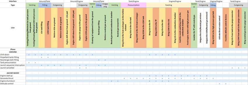
4) Problem statement

The purpose of this study is to explore the possible configurations of a feeding system for a
multiengine, reusable first stage. The number of engines is a parameter so the answer must be
adaptable. Several questions can be asked such as: how to rout the pipes in a constraint space? How
to divide the flow between the tank and several engines? How to connect the rocket and its tanks to
the ground? Which fluid functions can be merged in one pipe? Answering these questions allows to
have first calculations for design or future reflections. Moreover, it gives a possibility to discuss with
the team developing the engine to take into account some constraints which are common to all rocket
stages and especially their connections with the engine.

In parallel to this study several side questions or aspects were dealt with like technological review,
comparative study or methane passivation.

First a general view on the feeding system was adopted in order for the author to gain insight of all the
functions and subsystems used in the engine. All the different functions, implying fluids, were
considered, drains and fill operations for example, and not only the feeding ones. After this study the
subject was centered again on the feeding system and more precisely on the liquid oxygen feeding
lines.

The feeding system regroups all the pipes, valves, bellows and articulations which go from the tanks
to the turbopumps, i.e. the engine. For a basic liquid propellant engine there are three main fluids: the
oxidizer (LOx), the fuel (LH2, LCH4, RP-1) and a neutral gas (Nitrogen, Helium). All of them can be found
as a gas or a liquid in the engine. Propellants, the oxidizer/fuel couple, are used to feed the Gas
Generator which will power the turbine and as the main source of energy to propel the rocket in the
combustion chamber. Some of the exhaust gases can be used to control the attitude of the rocket. A
part of the propellants can also be used to pressurize the tanks. Neutral Gas is used to activate or
deactivate valves, to clean combustion chambers, to pressurize tanks and to isolate the oxidizer from
the fuel before the combustion chamber. As one can see, it can be difficult to separate the engine from
the rest of the stage as some fluids flow back from the engine to the tanks. The neutral gas is not used
to propel anything but its role in the feeding system cannot be ignored.

Both propellants have a very similar system and very close constraints so to study one is enough to
deal with both cases. It is quite easy to get some big figures on the fuel feeding system afterwards.

 5) Hypothesis

Without loss of generality, the number of engines for the present study was fixed to seven. This value
was chosen because some data had already been worked at AG. But adaptability to a different number
of engines was considered as a parameter. From this internal study, come the masses of propellants
and several dimensions of the rocket. With seven engines, the rocket has a 5.4 m diameter. There is
one central engine and six external engines which are placed on a hexagon.
All the engine data was extracted from Prometheus development.

The LOx tank is above the LCH4 tank and the main LOx feedline is internal to the methane tank. This
will limit the possible configurations for the feeding system.

 6) Mission definition

Internal studies at ArianeGroup have identified several steps in order to bring back to earth a first stage
equipped with Prometheus engines:
Ce document et les informations qu'il contient sont propriété d’Ariane Group SAS. Il ne doit pas être utilisé à d'autres fins que celles pour lesquelles il a été remis. Il ne peut
être ni reproduit, ni divulgué à des tiers (en tout ou partie) sans l'accord préalable et écrit d’Ariane Group SAS. Ariane Group SAS – Tous droits réservés. This document
and the information it contains are property of Ariane Group SAS. It shall not be used for any purpose other than those for which it was supplied. It shall not be reproduced
or disclosed (in whole or in part) to any third party without Ariane Group SAS prior written consent. Ariane Group SAS – All rights reserved.
- Ground: when the loading of propellants and the chill-down are performed
 - Ascending boost: liftoff and ascension
 - Toss-back boost: after stage separation, a boost to reorient the rocket toward the launch site
 - Braking boost
 - Landing boost. It is a soft landing featuring deep throttling of the engine and accurate
 regulation.
 - Coast phase (between each boost phase): short duration (no need to chill-down the engine
 again)

For a nine engines rocket like the Falcon 9, Table 2, which gives a frame for the present study, sums-
up the characteristics of the different phases. The same description was made in AG for a seven engines
rocket but it is not presented here.

 Ascending Toss-back
 Braking boost Landing boost Coast phases
 boost boost
 Duration (s) 150 30 15/5 30
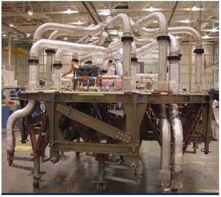
II. METHODS

 1) Comparative study

The first task of this project was to perform a comparative study of existing systems and projects having
a multiple engines first stage. Elements such as the number of engine, the temperature of the
propellants, the routing of the lines, the fill and drains ports of the tanks, the use of POGO devices, the
flowrates or the number of valves was retrieved or estimated for each engine. Two former feeding
system were of special interest to study: Ariane 4 rocket and the space shuttle main engine [1] as it
 as easie to fi d data a out the . Fo e e o kets, data as olle ted o o pa ies’ use s’ guide
[2], [3] and press-kit [4], [5], [6] o i te ie s of o pa ies’ a age s.

The goals were to determine how the routing of lines were made for multiengine rockets, what
interesting design choices were made for manifolds or flow separation devices or if the lines cross one
of the tanks. But it also allows to highlight past and future trends in space propulsion: in terms of
propellants or tanks design for example.

 2) Functional analysis

Without considering any physical subsystems, what are the most important functions for which a fluid
is used or transported to or from the engine?

It is interesting to answer to this question in order to know the basic needs in fluids of the engine. The
second step is to analyze when and how many times these functions are used. This require knowing
the diffe e t phases of the o ket’s life. The it is possi le to e ge so e functions. The final step is
to associate with each function or set of functions a physical system such as a pipe or a valve.

Functions were determined based on the study of internal documents and of engine flow diagrams.

 a) Basic needs of the engine

The most important function is generating thrust. To accomplish this one, several tasks need to be
performed:

 - Chill down the engine and all the lines: the propellants are cryogenic and when they are put in
 contact with the rocket, they will boil off. To get stable state conditions, a constant flow of
 propellant must be set in place until the solid parts in contact with fluid are at the right
 temperature.
 - Load and store propellants
 - Load and store a neutral gas. The neutral gas can be used to vent and clean combustion
 chamber, to activate valves, to isolate rotating parts or to pressurize tanks.
 - Convey propellants from tanks to engine
 - Pressurize tanks: to ensure the structural integrity of the tanks and the proper inlet pressure
 at the turbopump.

These functions in turn call for other sub-functions such as turning on/off the engine, outgas gaseous
p opella ts, u load li uid p opella ts o pe fo attitude o t ol …

Ce document et les informations qu'il contient sont propriété d’Ariane Group SAS. Il ne doit pas être utilisé à d'autres fins que celles pour lesquelles il a été remis. Il ne peut
être ni reproduit, ni divulgué à des tiers (en tout ou partie) sans l'accord préalable et écrit d’Ariane Group SAS. Ariane Group SAS – Tous droits réservés. This document
and the information it contains are property of Ariane Group SAS. It shall not be used for any purpose other than those for which it was supplied. It shall not be reproduced
or disclosed (in whole or in part) to any third party without Ariane Group SAS prior written consent. Ariane Group SAS – All rights reserved.
Moreover it is necessary to add systems in case of a launch abort before and after connectors
disconnections (not needed if disconnections happen after liftoff) and a safing system for the rocket,
i.e. emptying the tanks and venting the combustion chamber, after the final extinction of the engine.

This passivation function is the new aspect which must be considered when designing a rocket. On
Ariane 5 upper stage, passivation is already performed on orbit after completion of the mission: the
upper stage is venting its tanks while reaching a graveyard orbit or an orbit with a perigee low enough
to allow a de-orbitation in less than 25 years.

Having several engines does not change the functions, but it plays a role in the design of the piping
system, as one needs to add a manifold for example.

 b) Physical subsystems

Once the previous task has been performed, one can see when the lines will be used and how many
times. It is now possible to merge a few functions as the minimum number of lines is preferable. The
feasibility of merging functions can be checked with existing systems. For example, the filling operation
of a tank can be performed through a feeding line or directly through a dedicated line. Both systems
are used on Ariane 5. It also shows when and where the flow of a fluid must be stopped, which give
the number and position of valves.

However, this will give a result very close to what is actually done on A5 first stage. Interesting points
come from two specific aspects of a Prometheus based rocket: methane and reusability. Using
methane implies that new subsystems must be added to the rocket. Reusability means that just like
the upper stage of Ariane 5, the landing first stage must be able to vent its tanks and passivate the
whole fluid lines.

 c) Routing of feeding lines

Until this point, this functional analysis has been made from a very general viewpoint. It was done so
to give the author better knowledge on interactions between stage and engine in a rocket, to integrate
the study of methane related issues in this thesis and also to check what specific needs could come
from reusability and multiengine capacity. However, real design choices could be made on the feeding
system and especially on the LOx feeding lines.

The routing was imposed until the outlets of the tanks: both LOx and LCH4 outlets are located at the
bottom of the LCH4 tank as it was stated in the hypothesis section. From the outlets to the engines, a
design had to be proposed. Several configurations were presented, some of them were based on
existing systems. These configurations answer to different drivers: simplicity and repeatability of lines,
cost by limiting the number of feeding valves, number of engines.

 3) Qualitative trade-off

A first qualitative tradeoff was made in order to select the configurations presented above which could
be interesting to study in more detail.

Classic drivers in the space industry are weight and cost. Volume as well plays its role: cluttering must
be limited if one wants to be able to put all the required equipment or if an operator has to access to
the first stage. Solutions must minimize all these constraints but industrialization and fabrication must
also be taken into account. Repeatability of the lines (diameter, geometry, thickness) and a low number
of pipes can help to facilitate the industrialization. Criteria specific to a feeding system are: pressure
Ce document et les informations qu'il contient sont propriété d’Ariane Group SAS. Il ne doit pas être utilisé à d'autres fins que celles pour lesquelles il a été remis. Il ne peut
être ni reproduit, ni divulgué à des tiers (en tout ou partie) sans l'accord préalable et écrit d’Ariane Group SAS. Ariane Group SAS – Tous droits réservés. This document
and the information it contains are property of Ariane Group SAS. It shall not be used for any purpose other than those for which it was supplied. It shall not be reproduced
or disclosed (in whole or in part) to any third party without Ariane Group SAS prior written consent. Ariane Group SAS – All rights reserved.
d op i the li es a d the desi ed e gi e g oup o t ols i di idual, … . F o the ultiple e gi es
first stage comes two constraints: versatility to the number of engines and the adaptability to a central
engine.

All the configurations were evaluated with a mark over ten on these criteria.

 4) Quantitative study
 a) 3D design

CAD drawings, for only two of the selected configurations were made, in order to check the values
computed and the feasibility of a given routing. Other configurations were discarded after the
qualitative trade-off. It allowed to get more precise lengths of pipes, determine the number of elbows
and to check the total mass and volume of the system. Actually, two 3D designs were made, one using
CATIA and the other one using SkyReal software. SkyReal is a CAD software based on virtual reality
(VR) and it helps a lot for checking superposition and space related issues. It facilitates and accelerates
a lot the routing of fluid lines between existing components.

 b) Design values

Fo the th ee sele ted o figu atio s, the ass flo ates e e oted fo ea h step of the o ket’s life
and each pipe. Then the velocities and the pressure losses were estimated by adding a number of
equipment such as valves, POGO suppressor devices and by choosing a design with a number of elbows
a d dia ete s fo the su essi e pipes. The si gula p essu e d op o putatio as ased o Idel’ ik
[7]. Table 3 details the number of elbows and equipment on each line:

 Equipment LOx feeding system LCH4 feeding lines
 Bellow 6 1
 Spherical linkage 4 1
 Feeding valve 1 1
 POGO suppressor
 1 0
 device
 Tank filter 1 1
 Manifold/Flow
 0
 separation device
 Elbows 3
 Table 3: List of devices other than pipes on each feeding system. These devices are taken into account for pressure losses.

No POGO suppressor device was considered for the LCH4 feeding system as it is not used on other
multiengine rockets or on Ariane rockets for the fuel feeding lines.

For regular pressure losses, a friction coefficient, , as et ie ed f o Mood ’s diag a . With a
common roughness of 50 µm for all pipes, it gives a coefficient of about 0.012. Pressure drop is then
computed by:

 Δ =

Ce document et les informations qu'il contient sont propriété d’Ariane Group SAS. Il ne doit pas être utilisé à d'autres fins que celles pour lesquelles il a été remis. Il ne peut
être ni reproduit, ni divulgué à des tiers (en tout ou partie) sans l'accord préalable et écrit d’Ariane Group SAS. Ariane Group SAS – Tous droits réservés. This document
and the information it contains are property of Ariane Group SAS. It shall not be used for any purpose other than those for which it was supplied. It shall not be reproduced
or disclosed (in whole or in part) to any third party without Ariane Group SAS prior written consent. Ariane Group SAS – All rights reserved.
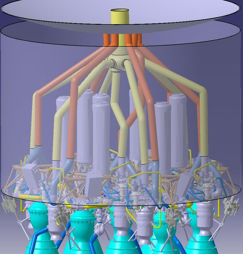
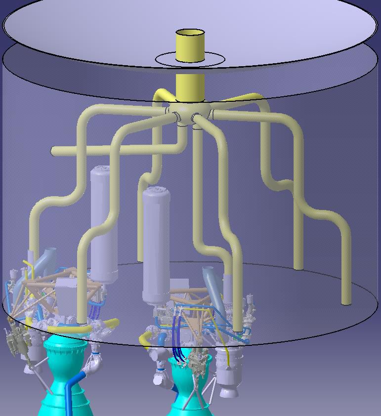
Pipe thickness was estimated by computing the hoop stress associated with a criterion based on
similarity with Ariane 5 design. The total mass between feeding system configurations was compared.
The material was assumed to be stainless steel with a density of 8 250 kg/m3. This is a conservative
hypothesis because aluminum can also be used for some parts of a feeding line.

Velocities in lines must be lower than a certain limit: for LOx it is 15 m/s and for LCH4 26 m/s.

Once the first boost phase is performed, only three engines will be re-ignited and the landing is done
on one engine, as stated in the Mission definition section. During engine shutdown, the feeding valve
will be closed. All the propellant below the valve will be drained in the purge connector. But above the
valve, it can be trapped between the valve and an elbow or the manifold. This phenomenon is called a
dead arm. The risk is that the fluid will increase in temperature, vaporize and could cause a water
hammer effect if a pressure wave re-liquefies the bubble of gas. It is a condensation induced water
hammer. This will endanger the integrity of the pipe and/or of the valve. The possibility of dead arms
was taken into account.

Figure 1 explains the distinction between main, intermediary and secondary lines:

 Figure 1: Schematic view of a generic LOx feeding system.

Each secondary line is feeding one engine and each intermediary line is feeding two or three engines.

Table 4 gives the chosen diameters and lengths used for calculations. Lengths were checked on CATIA
in order to get values as close as possible to the real dimensions. The choice for diameters is explained
in Mu a ’s la . Blues lines are for the 4 manifolds configuration, yellow for the single manifold and
orange for the Lyre configuration. Details about these different feeding systems are given in Routing
of feeding lines.

Ce document et les informations qu'il contient sont propriété d’Ariane Group SAS. Il ne doit pas être utilisé à d'autres fins que celles pour lesquelles il a été remis. Il ne peut
être ni reproduit, ni divulgué à des tiers (en tout ou partie) sans l'accord préalable et écrit d’Ariane Group SAS. Ariane Group SAS – Tous droits réservés. This document
and the information it contains are property of Ariane Group SAS. It shall not be used for any purpose other than those for which it was supplied. It shall not be reproduced
or disclosed (in whole or in part) to any third party without Ariane Group SAS prior written consent. Ariane Group SAS – All rights reserved.
Line Relative diameter Relative section Length (m)

 Main 2,3 5,3 15,30
 Intermediary 1,4 1,8 2,39
 Central intermediary 1,6 2,5 1,00
 Secondary 1,0 1,0 2,04
 Central secondary 1,0 1,0 2,91
 Secondary central engine 1,0 1,0 1,66
 Secondary 1,0 1,0 4,10
 Central secondary 1,0 1,0 2,76
 Secondary 1,0 1,0 19,00
 LCH4 secondary 1,0 1,0 4,00

Table 4: Diameters, section and length of the pipes in each configuration. Diameters and sections are relative to the TP inlet
 diameter.

 c) Murray’s law

O the Fal o 9 o figu atio , the e a e the ai LO li e a d the 7 secondary lines. The hydraulic
s ste has t o a ks. O the o figu atio alled a ifolds , the a k is th ee, e ause the
intermediary lines are added. One can wonder how to choose the evolution of the diameters between
each successive pipe, i.e. each rank, and what could be an optimal feeding system.

Co i g f o iolog a d a ato , the Mu a ’s la [8] can help answering this question. It states
that the cube of the radius of a parent vessel equals the sum of the cube of the radii of the daughters.
It was derived in 1926 by C.D. Murray [9] by minimizing the total work of a fluid, blood in his case,
going through a pipe, the vascular system. The work was divided in two: one part is the friction losses
and the other one is the cost of operating the volume of fluid. The flow was considered laminar. Results
coming from this theory were in good accordance with experimental values. Meaning that the system
is optimized.

It is possible to generalize this method [10], [11] by keeping the losses due to friction but considering
that the second term is either a cost associated with the surface or the volume of the system. This
term is coming from a constraint on the size of the system. For the feeding system of a rocket, one
wants to minimize the mass. Considering a turbulent flow will also change the aspect ratio between
two consecutive vessels.

A Poiseuille turbulent flow in a circular pipe of diameter D and length L gives the following pressure
drop:

 8 ̇
 Δ =

Where ̇ is the mass flow rate and the f i tio oeffi ie t o i g f o Mood ’s diag a . The po e
lost due to friction is then:

Ce document et les informations qu'il contient sont propriété d’Ariane Group SAS. Il ne doit pas être utilisé à d'autres fins que celles pour lesquelles il a été remis. Il ne peut
être ni reproduit, ni divulgué à des tiers (en tout ou partie) sans l'accord préalable et écrit d’Ariane Group SAS. Ariane Group SAS – Tous droits réservés. This document
and the information it contains are property of Ariane Group SAS. It shall not be used for any purpose other than those for which it was supplied. It shall not be reproduced
or disclosed (in whole or in part) to any third party without Ariane Group SAS prior written consent. Ariane Group SAS – All rights reserved.
̇ 8 ̇
 ̇ = Δ =

This corresponds to the power required to pump the liquid through the pipe. Minimizing it means
enlarging as much as possible the diameter of the pipe.

The mass of a single pipe is given by ≈ where a is the ratio of the thickness over the diameter
of the pipe, as one can consider that the thickness is directly proportional to the diameter when
keeping the hoop stress constant. Minimizing the mass means reducing as much as possible the
diameter of the pipes.

Now for the whole system, with several ranks of pipes, the total power and the total mass are
summations over the number of vessels:

 8 ̇
 ̇ = ∑

 = ∑

Using a Lagrange multiplier it is possible to find an optimum between minimization of the pumping
power and minimization of the mass. One can write = ̇ + . The optimization gives:

 ̇
 = ⇒ =

Inserting in the total power gives ̇ = /5. Minimizing the total pumping power is equivalent to
minimizing .

Inserting in the total mass gives:

 /
 /
 ∑ ̇ =

Minimizing is equivalent to minimizing the sum on the left of the last equation. The mass flow rate
raised to the power 6/7 can be seen as a cost per unit length of the hydraulic system. With this cost,
another interesting side result can be obtained: the optimal angle at a T-junction. At this junction, no
mass flow is consumed and using the method described by Gilbert [12], an optimal angle between the
two daughter vessels can be calculated.

 d) Pressurization needs

By computing the tank pressure for both propellants as well as the mass of pressuring gas needed, the
feeding system can be connected with its two endpoints: the tank and the engine. Indeed, the tank
pressure is the value which is of interest for the tank designers and is partly given by the feeding system
itself – pressure losses, height - and partly by the engine - turbopumps need a minimum amount of
pressure to work without cavitating. The value of the mass of gas required for pressurization is of
interest for people working on the whole stage as it will impact the total mass, i.e. the performance of
the launcher.

Ce document et les informations qu'il contient sont propriété d’Ariane Group SAS. Il ne doit pas être utilisé à d'autres fins que celles pour lesquelles il a été remis. Il ne peut
être ni reproduit, ni divulgué à des tiers (en tout ou partie) sans l'accord préalable et écrit d’Ariane Group SAS. Ariane Group SAS – Tous droits réservés. This document
and the information it contains are property of Ariane Group SAS. It shall not be used for any purpose other than those for which it was supplied. It shall not be reproduced
or disclosed (in whole or in part) to any third party without Ariane Group SAS prior written consent. Ariane Group SAS – All rights reserved.
The tank pressure, , is given by:

 ̇
 = + Δ + Λ + − ℎ

Where is the required pressure at the entrance of the turbopump and it is given by the
engine. Δ is the pressure losses along the feeding lines. Λ is the inductance of the line and is equal to
the ratio of the length over the section of the pipe. is the vapor pressure of the propellant (around
1.1 bar for liquid oxygen at 90 K). is the current acceleration of the launcher and ℎ is the height of
the fluid column which is close to the length of the pipe added to the height of the tank when it is full.

If a parent vessel, named 1, with a mass flow rate ̇ = ̇ is split in two daughter vessels, named 2,
each with a mass flow rate ̇ , the inductance of the system, along one line, is given by:

 Λ = Λ +Λ

The term with the inductance models the pressure drop when the flow is started. It is during this
transient phase that the pressure requirement on the tank is the highest at a given flight phase. The
most dimensioning flight phase in terms of tank pressure, during a toss-back maneuver, is the second
boost because a large part of the propellant has been consumed so the contribution of the hydrostatic
height to the entrance pressure of the pump will be small. Thus, the tank pressure has to be higher.

The hydraulic head has two variables: height ℎ and acceleration . During the ascent boost, the height
decreases from about ten meters down to just a few meters. But this is compensated by the
acceleration that will be several times the gravity. It is on the ground, during liftoff, that the
requirement on the tank pressure will be the highest as explained above. During the Toss-back boost,
height decreases a little bit and the acceleration will increase from no gravity up to several times the
gravity. It is again during engine start up that the tank pressure will have to be high.

Once this tank pressure is known it is possible to calculate the mass of gas needed to maintain
at the desired value. This can be done using an equation derived by Epstein [13] associated with
coefficients determined by Epstein and Anderson [14]. Coefficients were fitted to experimental data.
The idea is that knowing the volume of propellant consumed by the engines, one can compute the
mass of pressurization gas, assumed to be a perfect gas, needed to fill the void, and then to correct
this value using the Epstein equation.

Epstein equation gives results with a precision of 12% as long as one stays in the range covered by the
hypothesis. It takes into account the radiative flux on the tank walls and thermal exchanges due to
convection. This equation is used at AG as a quick way to estimate pressurization needs for draft
projects.

The pressurization system is said to be autogenous, if the pressurization gas is the same fluid as the
propellant stocked in the tank. Here, GOx and GCH4 would be used in this case. Otherwise, a neutral
gas such as Nitrogen or Helium can replace the gaseous propellants. An autogenous system is harder
to conceive for oxygen, but it allows to eliminate or to greatly reduce the size of the neutral gas tank.
For a Prometheus engine, the pressurization should be autogenous but both cases were considered
and Helium was the chosen Neutral gas.

The volume of propellant consumed by the engines can be computed using the values given in the
mission definition and the mass flow rate corresponding to the thrust required. For a seven engines
rocket and an ascent boost duration of 150 s, the total mass of propellant consumed is around 365t,
Ce document et les informations qu'il contient sont propriété d’Ariane Group SAS. Il ne doit pas être utilisé à d'autres fins que celles pour lesquelles il a été remis. Il ne peut
être ni reproduit, ni divulgué à des tiers (en tout ou partie) sans l'accord préalable et écrit d’Ariane Group SAS. Ariane Group SAS – Tous droits réservés. This document
and the information it contains are property of Ariane Group SAS. It shall not be used for any purpose other than those for which it was supplied. It shall not be reproduced
or disclosed (in whole or in part) to any third party without Ariane Group SAS prior written consent. Ariane Group SAS – All rights reserved.
of which about one third will be methane. Thus, it is easy to compute the volume consumed during
this part of the flight.

The mass of pressurization gas is largely driven by the temperature at which it will be injected in the
tank. If it were a perfect gas, it would be directly proportional. All pressurization gases, the system
being autogenous or not, goes through a heat exchanger and are then injected in the tank. Injection
temperature of oxygen, for example, can be derived by saying that the liquid oxygen is first vaporized
in the heater before being heated to the required temperature. Knowing the mass flow rate, ̇ ,
through the heat exchanger, the inlet temperature of the fluid, , and the thermal power
exchanged, , in this equipment, one can compute the injection temperature using this formula:

 = +( − Δ )
 ̇

The power of the heat exchanger is an information coming from the engine development team.
Tank material is Aluminum 2219 with a density of 2 823 kg/m3 and a yield strength of 276 MPa.
Stiffeners are not considered here.

 e) Amesim models

Amesim is a simulation software for the modelling of 1D systems. It can cover several fields such as
fluid mechanics, heat transfer or mechanics. A global system is modelled by pre-defined components
like pipes or springs. Amesim establishes and solves the differential equations corresponding to this
assembly of components. At AG, it is used to model an engine or a whole stage for example.

Here the purpose is to use the data computed before in order to define models of multiengine feeding
systems which could be a base for future works. Two configurations are studied here. Only the LOx
feeding system was modelled through Amesim.

The first version of this model was really simple and the tank or the engine were replaced by constant
signal values. Tanks can be modeled as flow sources with an unlimited amount of propellant. Engines
can be considered as flow sinks. Thus, the model will contain only pipes and flow separation devices.
It is really easy to add a more developed engine to this model in the form of the exact list of values of
mass flow rate needed during the flight for example. However, it does not give much more information
than sinks with step values.

This simple model also helps to familiarize oneself with the Amesim software. Components used here
were defined internally at AG and are not part of Amesim standard libraries. Figure 2 and Figure 3
show the two models.

Lengths, diameters and pressure drop coefficients were defined for each pipe based on calculations
and on CAD files derived in the previous sections. Acceleration of the whole system is taken into
account.

The model can be used to simulate different life phases of the real system. But, only the first boost,
i.e. the ascent phase, will be studied. The greatest part of the propellant is consumed during this part
of the mission so knowing the behavior of the feeding system at this step is crucial.

Flow separation devices only split the flow and they do not count as small capacities, nor do they
consider pressure losses. Pressure losses due to manifolds or flow separation devices were added
directly to the pipes.

Ce document et les informations qu'il contient sont propriété d’Ariane Group SAS. Il ne doit pas être utilisé à d'autres fins que celles pour lesquelles il a été remis. Il ne peut
être ni reproduit, ni divulgué à des tiers (en tout ou partie) sans l'accord préalable et écrit d’Ariane Group SAS. Ariane Group SAS – Tous droits réservés. This document
and the information it contains are property of Ariane Group SAS. It shall not be used for any purpose other than those for which it was supplied. It shall not be reproduced
or disclosed (in whole or in part) to any third party without Ariane Group SAS prior written consent. Ariane Group SAS – All rights reserved.
During the ascent boost, the dimensioning part in terms of tank pressure is the engines start up as
explained above. So only the first seconds are needed and were actually simulated. Thus, the value of
the acceleratio of the s ste as set to Ea th’s g a it .
A few iterations were made for each configuration in order to reach the right pressure value at the
bottom of the LOX tank which is the starting value in this model. This pressure must be large enough
so that the pressure at the entrance of the pump, , is higher than the . These two
pressures are linked by the following equation:

 = − −

Where is a few hundred millibars. To respect this criterion, must be superior or equal to
around 4 bar and this has to be true for all the engines.

Figure 2: Amesim model for the 4 manifolds configuration. Blue lines simply transfer fluid from one pipe element to another.
 Pipe elements represent real pipes with length, diameter, hydraulic head and pressure drop coefficient. No thermal load is
considered. The (P, T) element on the left represents the tank with two constants inputs. (P, T, ̇ ) elements on the right are
fluid sinks and the mass flow rate is a step input signal. Flow separators only split the flow without changing the pressure or
 the temperature.

Ce document et les informations qu'il contient sont propriété d’Ariane Group SAS. Il ne doit pas être utilisé à d'autres fins que celles pour lesquelles il a été remis. Il ne peut
être ni reproduit, ni divulgué à des tiers (en tout ou partie) sans l'accord préalable et écrit d’Ariane Group SAS. Ariane Group SAS – Tous droits réservés. This document
and the information it contains are property of Ariane Group SAS. It shall not be used for any purpose other than those for which it was supplied. It shall not be reproduced
or disclosed (in whole or in part) to any third party without Ariane Group SAS prior written consent. Ariane Group SAS – All rights reserved.
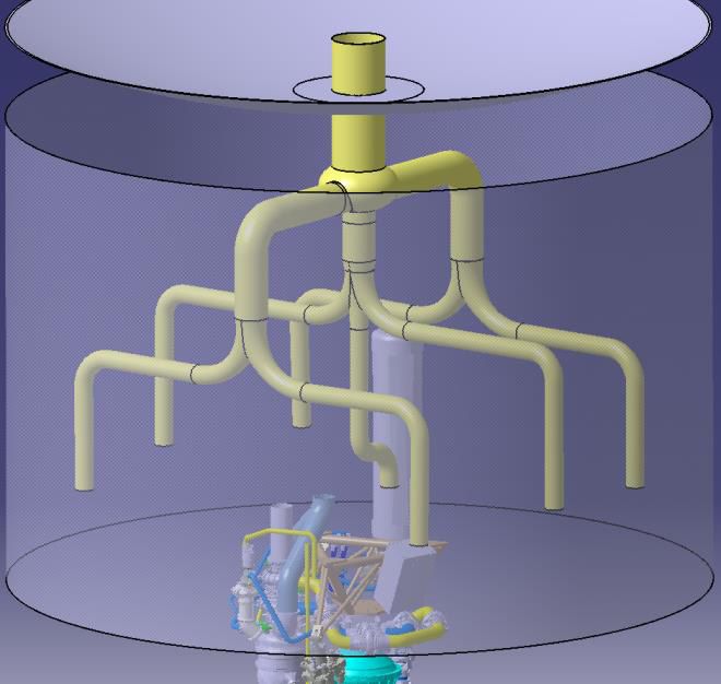
Figure 3: Amesim model for the single manifold configuration. The central engine is the bottom one.

 5) Surface functionalization study

In combination with the team working on 3D printing at AG, the possibility and feasibility of surface
functionalization was reviewed. This is not specially linked to Themis, but it could be a potential
improvement which could be implemented on Ariane Next.

The purpose is to create an artificial and controlled roughness which can reduce flow friction. This
te h i is ofte efe ed to as Sha k Ski . He e, it would be of interest inside vessels carrying
propellants. A bibliographic study was made and a few companies doing laser functionalization were
contacted.

III. RESULTS

 1) Comparative study

Table 5 and Table 6 present the work done for this comparative study. Other rockets which were
reviewed are presented in Appendix 1.

Ce document et les informations qu'il contient sont propriété d’Ariane Group SAS. Il ne doit pas être utilisé à d'autres fins que celles pour lesquelles il a été remis. Il ne peut
être ni reproduit, ni divulgué à des tiers (en tout ou partie) sans l'accord préalable et écrit d’Ariane Group SAS. Ariane Group SAS – Tous droits réservés. This document
and the information it contains are property of Ariane Group SAS. It shall not be used for any purpose other than those for which it was supplied. It shall not be reproduced
or disclosed (in whole or in part) to any third party without Ariane Group SAS prior written consent. Ariane Group SAS – All rights reserved.
Re-entry in atmospheric Mission phase for engine Oxidizer flowrate (engine- Fuel flowrate (engine-
 Number of engine Have flown Re-ignitable engine Oxidizer Fuel Thrust Vector Control
 ambiance re-ignitions global) globa)
 Next Shuttle Launch (no engine re-
 ignition during re-entry phase)
 LOX LH2
 3
 Space Shuttle Main Engine yes yes yes 91K 20K gimballing the engines 424 kg/s - 1272 kg/s 70 kg/s - 210 kg/s
 (triangular configuration)
 1140 kg/m3 70 kg/m3

 5 LOX RP1
 Saturn V 1st stage
 (one in the center and others are yes no no - 91K 293 K gimballing the engines 1790 kg/s - 8950 kg/s 788 kg/s - 3940 kg/s
 (F-1 Engines)
 on a square) 1140 kg/m3 820 kg/m3

 5 LOX LH2
 Saturn V 2nd stage
 (one in the center and others are yes no no - 91K 20K gimballing the engines 204 kg/s - 1020 kg/s 37 kg/s - 185 kg/s
 (J-2 Engines)
 on a square) 1140 kg/m3 70 kg/m3

 N2O4 UH 25
 4 gimballing the engines around
 Ariane4 1st stage yes no no - 293 K 173 kg/s - 694 kg/s 101 kg/s - 406 kg/s
 (Viking) one axis
 1450 kg/m3 850 kg/m3

 3 re-boosts:
 - Toss back boost
 9 - Re-entry boost Subcooled LOX RP1
 gimballing of each engine with 2
 Falcon9 1st stage (Merlin 1D engines in octaweb yes yes yes - Landing boost 66 K 266 K 213 kg/s - 1918 kg/s 92 kg/s - 828 kg/s
 hydraulic jacks
 configuration) 1250 kg/m3 820 kg/m3

 3 re-boosts:
 - Re-entry boost
 37 - Landing boost Subcooled LOX Subcooled LCH4
 Space X Super Heavy (BFR) (Raptor engines in 2 circles and no yes yes - Re-boost from earth to supply ?? K ?? K 443 kg/s - 16403 kg/s 117 kg/s - 4317 kg/s
 one cluster - can use less) shuttle 1250 kg/m3 422 kg/m3

 - Travel to Mars
 - Mars Landing
 6 - Mars take off Subcooled LOX Subcooled LCH4
 Space X Starship (Raptor engines, 2 Sea Level and 4 no yes yes - Earth re-entry and landing ?? K ?? K ?
 Vacuum) 1140 kg/m3 422 kg/m3

 N2O4 UDMH
 Dnepr Launcher 4 gimballing each nozzle around
 yes ? ? ? 293 K 293 K ?
 (1st stage) (RD264) one axis
 1450 kg/m3 790 kg/m3

 3 re-boosts:
 3x9 - Toss back boost
 - Re-entry boost Subcooled LOX RP1
 (Merlin 1D engines in octaweb gimballing each engine with 2
 Space X Falcon Heavy yes yes yes - Landing boost 66 K 266 K 213 kg/s - 1918 kg/s per booster 92 kg/s - 828 kg/s per booster
 configuration) (3 Falcon 9 side by hydraulic jacks
 1250 kg/m3 820 kg/m3
 side)

 Table 5: Comparative study of multiengine rockets. Part 1 a.

Ce document et les informations qu'il contient sont propriété d’Ariane Group SAS. Il ne doit pas être utilisé à d'autres fins que celles pour lesquelles il a été remis. Il ne peut être ni reproduit, ni divulgué à des tiers (en tout ou partie) sans l'accord préalable et écrit d’Ariane Group
SAS. Ariane Group SAS – Tous droits réservés. This document and the information it contains are property of Ariane Group SAS. It shall not be used for any purpose other than those for which it was supplied. It shall not be reproduced or disclosed (in whole or in part) to any
third party without Ariane Group SAS prior written consent. Ariane Group SAS – All rights reserved.
Vous pouvez aussi lire