IP IP AUDIO VIDEO IP Easy Installation Guide - Hager
←
→
Transcription du contenu de la page
Si votre navigateur ne rend pas la page correctement, lisez s'il vous plaît le contenu de la page ci-dessous
IP Easy Installation Guide
IP Easy Installation Guide
Guide d’installation rapide IP IP
AUDIO
IP
VIDEO
EASY SECURE FOCUSED Kommunikation und Sicherheit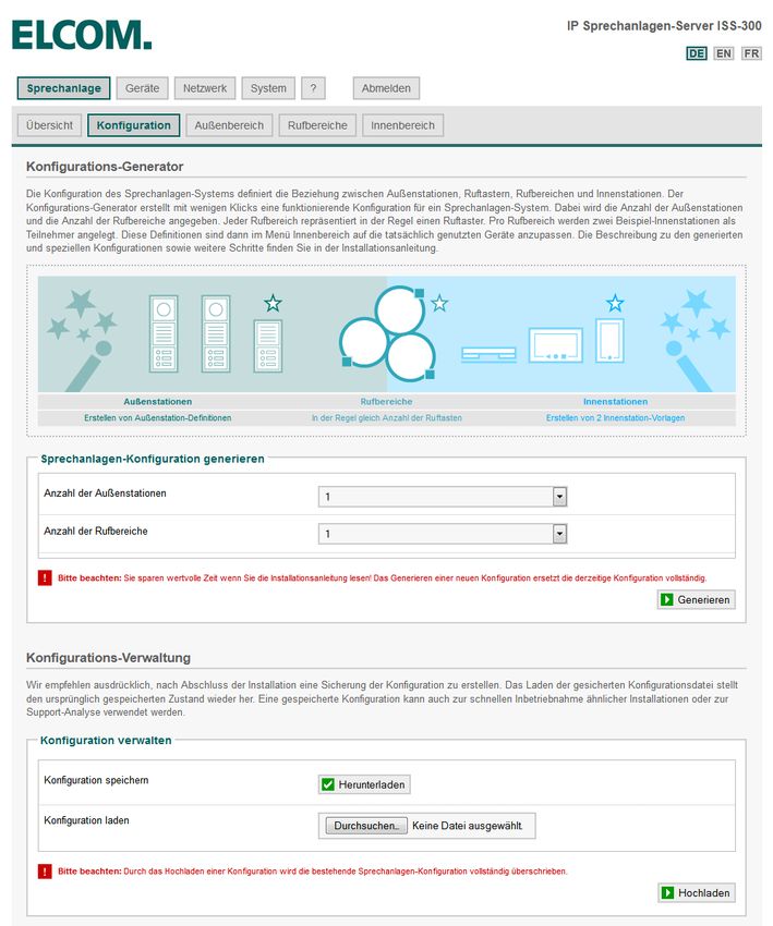
Willkommen
Welcome
Bienvenue

             EASY SECURE FOCUSED

INSTALLATION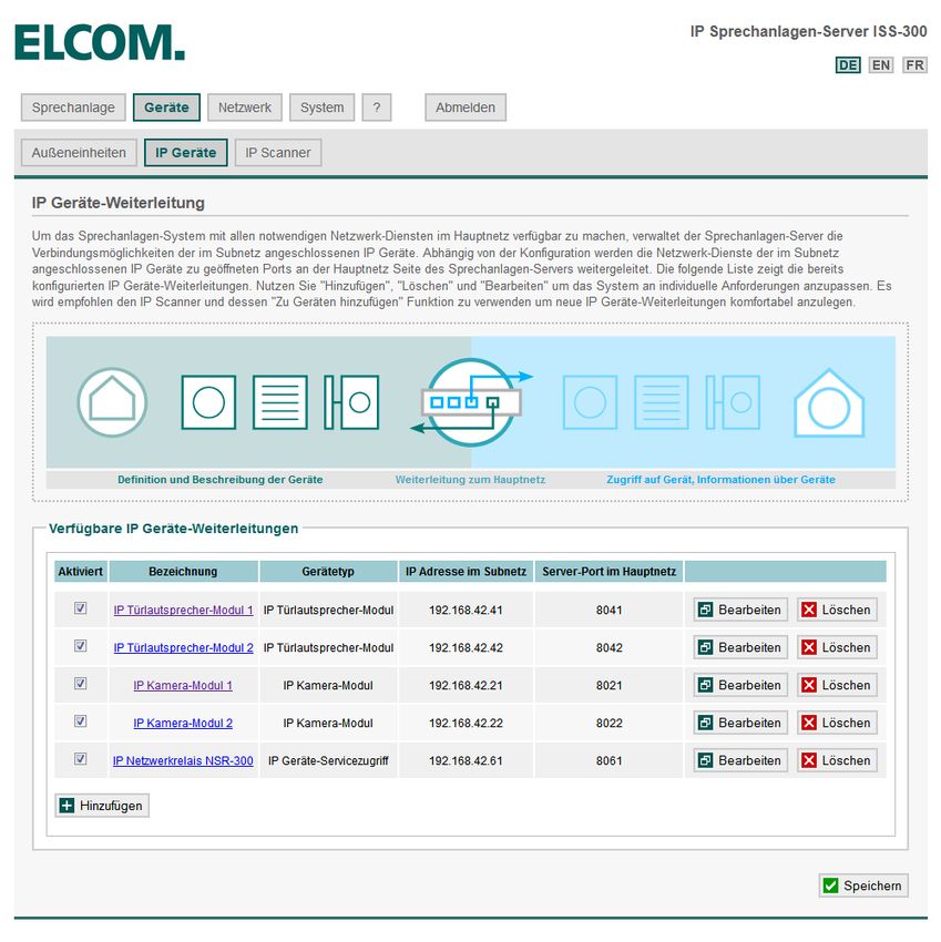
Inhaltsverzeichnis INSTALLATION
Table of contents · Sommaire Dokument: Version 2.2 Datum: 11.07.2015
Zeichenerklärung 4 Beispiel-Konfiguration dieser Anleitung 5
Signs and symbols Example configuration in this guide
Explication de symboles Exemple de configuration de cette notice
MONTAGE INSTALLATION MONTAGE GERÄTE DEVICES APPAREILS HAUPTNETZ MAINNET RÉSEAU PRINCIPAL
A1. Außeneinheit vorbereiten
Preparing the outdoor unit
6
C1. Zweite Außeneinheit mit Subnetz verbinden
Connecting the second outdoor unit to the subnet
23 - 24
E1. Sprechanlagen-Server auf statische Hauptnetz IP 42
Set intercom server to static main network IP
Préparer le module extérieur Connexion du second module extérieur au sous-réseau Serveur d‘interphone sur réseau principale IP statique
A2. Netzwerk-Infrastruktur vorbereiten
Preparing the network infrastructure
7
C2. IP Türlautsprecher der Einheit konfigurieren
Configuring IP door speakers in the unit
25 - 28
INNEN INDOOR INTÉRIEUR
Préparation de l‘infrastructure du réseau Configuration du haut-parleur de porte IP du module
A3. Sprechanlagen-Server aufrufen und anmelden
Access and log into the intercom server
8
C3. IP Kamera-Modul der Einheit konfigurieren
Configuring the IP camera module of the unit
29 - 32
F1. Innenstation konfigurieren - Übersicht
Configuring indoor stations - Overview
43
Ouverture et connexion au serveur d‘interphone Configuration du module de caméra IP du module Configuration d‘un poste intérieur - vue d‘ensemble
SYSTEM SYSTEM SYSTÉME
C4. Erste Außeneinheit mit Subnetz verbinden
Connecting the first outdoor unit to the subnet
33
F2. Innenstation konfigurieren - Registrierung
Configuring indoor stations - Registration
44
Connexion du premier module extérieur au sous-réseau Configuration d‘un poste intérieur - enregistrement
B1. Beschreibung Sprechanlagen-Systemübersicht
Description of the intercom system overview
9
C5. Sprechanlagen-Systemübersicht prüfen
Checking the intercom system overview
34
F3. Innenstation konfigurieren - Außenstationen
Configuring indoor stations - Outdoor stations
45
Description de la vue d‘ensemble du système d‘interphone Contrôler la vue d‘ensemble d‘interphone Configuration d‘un poste intérieur - postes extérieurs
B2. Konfigurationsvorlage definieren
Defining the configuration template
10 - 11
INTEGRATION INTEGRATION INTÈGRENT ABSCHLUSS FINALIZATION ACHÈVEMENT
Définition du modèle de configuration
B3. Konfiguration anpassen - Außenbereich
Adapting the configuration - outdoor area
12 - 14
D1. IP Netzwerk-Relais mit dem Subnetz verbinden
Connecting the IP network relay to the subnet
35
G1. System-Installation abschließen und prüfen
Completing and checking system installation
46
Adaptation de la configuration – espace extérieur Connexion du relais de réseau IP au sous-réseau Terminer et contrôler l‘installation du système
B4. Konfiguration anpassen - Rufbereiche
Adapting the configuration - call zones
15 - 17
D2. IP Netzwerk-Relais in das System integrieren 36 - 38
Integrating the IP network relay into the system
G2. System-Konfiguration sichern
Backing up the system configuration
47
Adaptation de la configuration - zones d‘appel Intégrer le relais de réseau IP dans le système Sauvegarde de la configuration du système
B5. Konfiguration anpassen - Innenbereich
Adapting the configuration - indoor area
18 - 21
D3. IP Netzwerk-Relais konfigurieren
Configuring the IP network relay
39 - 41 G3. Administrator-Passwort ändern
Changing the administrator password
48
Adaptation de la configuration - espace intérieur Modification du mot de passe d‘administrateur
Configuration du relais de réseau IP
B6. Sprechanlagen-Systemübersicht prüfen
Checking the intercom system overview
22
G4. Vom Sprechanlagen-Server abmelden
Logging off the intercom server
49
Contrôler la vue d‘ensemble d‘interphone Déconnexion du serveur d‘interphone
www.elcom.de 3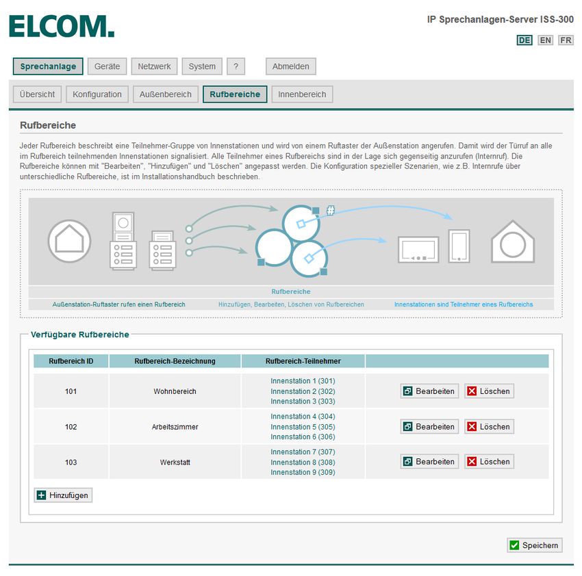
Zeichenerklärung INSTALLATION
Signs and symbols · Explication de symboles Dokument: Version 2.2 Datum: 11.07.2015
SUBNET MAINNET
Subnetz / Subnet / Sous-réseau Hauptnetz / Mainnet / Réseau principal
Außeneinheiten / Outdoor Units / Unités extérieur Inneneinheiten / Indoor Units / Unités intérieur
Video-Außenstation IP Kamera-Modul Android Client
Video Doorstation IP Camera Module Android Client
Portier vidéo Module caméra IP Android Client
Sprechanlagen-Server
IP Türlautsprecher-Modul Intercom Server iOS Client
IP Door Module Serveur d‘interphone iOS Client
Module porte IP iOS Client
Hauptnetz-Router
Mainnet router
Audio-Außenstation IP Kamera benutzerdefiniert Routeur de réseau principal Windows Client
Audio Doorstation IP Camera Generic Windows Client
Portier audio Caméra IP générique Windows Client
Rufbereiche
IP Netzwerk-Relais Call Zones Domovea Client
IP Network relay Zones d‘appel Domovea Client
Relais de réseau IP Domovea Client
Hauptnetz-Switch
Mainnet switch
Switch de réseau principal
IP Kamera IP Analog/VoIP-Adapter IP Telefonanlage,
IP Camera IP Analogue/VoIP adapter Subnetz-Switch (PoE) IP Telefon
Caméra IP Adaptateur IP analogique/VoIP Subnet switch (PoE) PBX / IP Phone
PBX / IP Phone
Switch de sous-réseau (PoE)
4 www.elcom.de
Beispiel-Konfiguration dieser Anleitung INSTALLATION
Example configuration in this guide · Exemple de configuration de cette notice Dokument: Version 2.2 Datum: 11.07.2015
SUBNET MAINNET
ISS-300
Hinweise / Notes / Notes
Das Beispiel zeigt die Installation einer Sprechanlage mit zwei Video-Aus- The example shows the installation of a intercom system with two outdoor L‘exemple montre l‘installation d‘un interphone avec deux postes vidéo ex-
senstationen und IP Netzwerk-Relais im Subnetz. Die Integration in das video stations and an IP network relay in the subnet. Integration into the térieurs et un relais de réseau IP dans le sous-réseau. L‘intégration dans le
Hauptnetz erfolgt über den Sprechanlagen-Server. Für das Netzwerk- main network takes place through the intercom system server. An additi- réseau principal s‘effectue via le serveur d‘interphone. Pour le relais de réseau,
Relais wird eine zusätzliche Spannungsversorgung 9 - 30 VDC benötigt. onal 9 - 30 VDC power supply is needed for the network relay. une alimentation électrique supplémentaire de 9 - 30 VCC est nécessaire.
www.elcom.de 5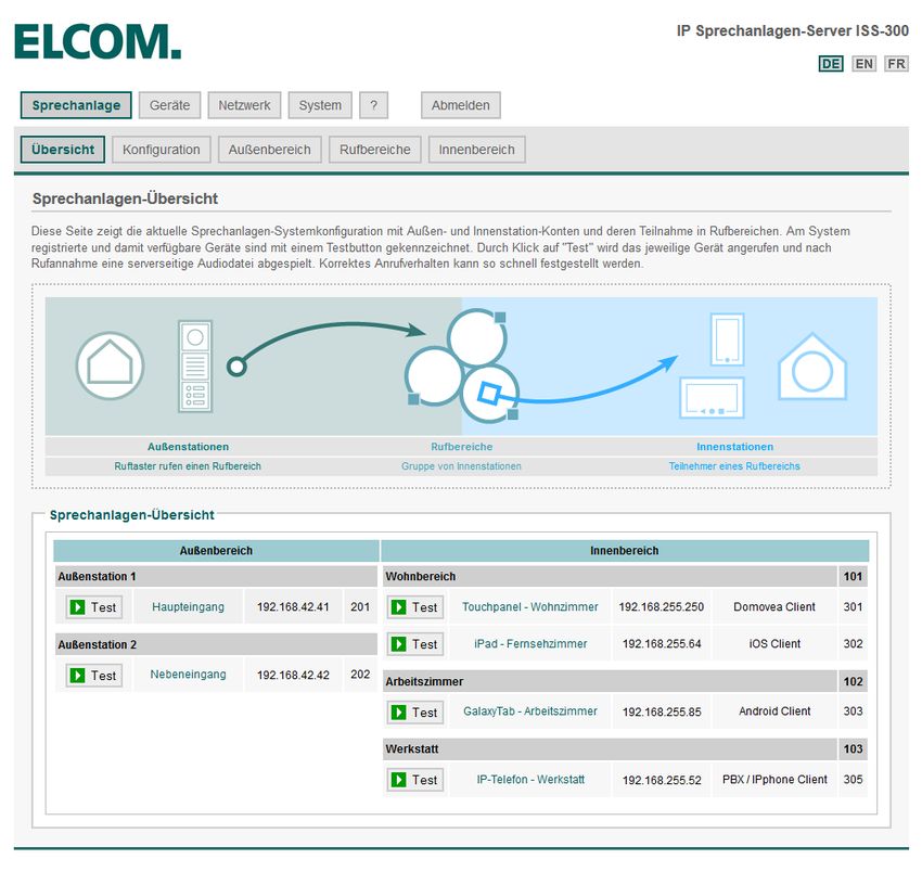
A1. Außeneinheit vorbereiten
Preparing the outdoor unit · Préparer le module extérieur
INSTALLATION
Dokument: Version 2.2 Datum: 11.07.2015
Verdrahten Sie das IP Türlautsprecher-Modul und die
Kamera und Anschlüsse und Klemmen wie folgt:
Input: zum Subnetzwerk (PoE-Switch)
Output: zur IP Kamera
5-9 rechts: Ruftaster 1 bis 4 (Z1-Z4 / GND)
NETWORK
4/5 links: Relais 1 (Türöffner)
INPUT 6/7 links: Relais 2 (Licht)
8/10 links: Ruftaster-Beleuchtung
Weitere Informationen in den Geräte-Anleitungen.
Wire the IP door speaker module and the camera,
connections and terminals as follows:
Input: To the subnetwork (PoE switch)
Output: To IP camera
5-9 right: Call buttons 1 through 4 (Z1-Z4 / GND)
4/5 left: Relay 1 (electric strike)
PE 6/7 left: Relay 2 (light)
0V S3B 8/10 left: Call button lighting
+UB GND
REL1.1 +5V You can find further information in the unit instructions.
REL1.2 LEDB
REL2.1 Z1
REL2.2 Z2 Câblez le module de haut-parleur de porte IP et la
+24V Z3
ELAN Z4 caméra avec les connecteurs et bornes comme suit :
GND GND
Input : Vers le sous-réseau (switch PoE)
Output : Vers la caméra IP
NETWORK NETWORK
5-9 à droite : Boutons d‘appel 1 à 4 (Z1-Z4 / GND)
EPORT
OUTPUT INPUT
4/5 à gauche : Relais 1 (gâche électrique)
6/7 à gauche : Relais 2 (éclairage)
8/10 à gauche : Eclairage de boutons d‘appel
Vous trouverez des informations complémentaires
dans les notices des appareils.
Hinweise / Notes / Notes
IP Türlautsprecher- und Kamera-Modul können über Power-Over- The IP door speaker and camera module can be supplied with pow- Les modules de haut-parleur de porte IP et de caméra peuvent être ali-
Ethernet oder ein separates Netzteil (28 VDC / NGV-500) versorgt wer- er through Power-Over-Ethernet or a separate power supply (28 VDC / mentés par Power-over-Ethernet ou par un bloc d‘alimentation distinct
den (Klemmen 0V und +UB). NGV-500) (terminals 0V and +UB). (28 VCC / NGV-500 – bornes 0V et +UB).
6 www.elcom.de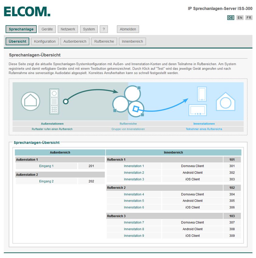
A2. Netzwerk-Infrastruktur vorbereiten
Preparing the network infrastructure · Préparation de l‘infrastructure du réseau
INSTALLATION
Dokument: Version 2.2 Datum: 11.07.2015
Bauen Sie die Netzwerk-Infrastruktur wie abgebildet
auf. Der Sprechanlagen-Server wird über den PoE-
Port (1) mit dem PoE-Switch des Subnetzes ver-
bunden. Einer der Ports 2, 3, 4 ist an das Hauptnetz
SUBNET MAINNET (Heim-/Firmennetzwerk) anzuschließen.
Wir empfehlen, die Konfiguration aus dem Haupt-
netz vorzunehmen. Hier bezieht der Sprechanlagen-
Server vom Router eine IP Adresse und wird im
Netzwerk per UPnP angekündigt.
Set up the network infrastructure as shown. The inter-
com server is connected through the PoE port (1) to
the PoE switch of the subnet. One of ports 2, 3, 4
must be connected to the main network (home/com-
pany network).
IP ISS-300 We recommend carrying out the configuration from
the main network. Here, the intercom server obtains
192.168.42.1 DHCP/UPnP an IP address from the router and is registered in the
(iss-300/UPnP) network via UPnP.
Constituer l‘infrastructure du réseau comme indiqué
sur la figure. Le serveur d‘interphone est relié par le
port PoE (1) au switch PoE du sous-réseau. Un des
!
ports 2, 3, 4 doit être raccordé au réseau principal
(réseau domestique/d‘entreprise).
Nous recommandons de procéder à la configuration
depuis le réseau principal. Ici, le serveur d‘interphone
reçoit une adresse IP qui lui est attribuée par le rou-
teur, et il est signalé au réseau par UPnP.
Hinweise / Notes / Notes
Verbinden Sie im ersten Schritt nur den Sprechanlagen-Server mit In the first step, only connect the intercom server to the PoE switch and Lors de la première étape, connectez le serveur d‘interphone au switch
dem PoE-Switch und dem Heim-/Firmennetzwerk. Die Außeneinhei- the home/company network. The outdoor units will be connected later. PoE et au réseau domestique/d‘entreprise. Les modules extérieurs sont
ten werden zu einem späteren Zeitpunkt angeschlossen. raccordés ultérieurement.
www.elcom.de 7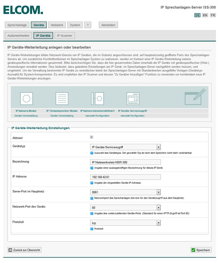
A3.     Sprechanlagen-Server aufrufen und anmelden
        Access and log into the intercom server · Ouverture et connexion au serveur ‘interphone
                                                                                                                        INSTALLATION
                                                                                                                         Dokument: Version 2.2   Datum: 11.07.2015

    M        Anmelden                                       Login                                       Connexion

                                                                                                  UPnP-Geräte werden unter Windows im Bereich
                                                                                                  „Netzwerk“ angezeigt. Ein Doppelklick auf das
                                                                                                  Symbol öffnet die Konfigurationsoberfläche im
                                                                                                  Webbrowser.
                                                                                                  Melden Sie sich am Sprechanlagen-Server an.
                                                                                                  Die werkseitigen Zugangsdaten lauten:
                                                                                                  Benutzername:		 root
                                                                                                  Passwort:		 1234

                                                                                                  UPnP devices are shown in the „Network“ area under
                                                                                                  Windows. Double-click the icon to open the configu-
                                                                                                  ration user interface in the Web browser.
                                                                                                  Log into the intercom server. The factory access data
                                                                                                  are as follows:
                                                                                                  Username: 		            root
                                                                                                  Password:		             1234

                                                                                                  Les appareils UPnP s‘affichent sous Windows dans
                                                                                                  la rubrique « Réseau ». Un double clic sur le symbole
                                                                                                  ouvre l‘interface de configuration dans le navigateur
                                                                                                  Web.
                                                                                                  Connectez-vous au serveur d‘interphone.
                                                                                                  Les données d‘accès d‘usine sont :
                                                                                                  Nom d‘utilisateur :     root
                                                                                                  Mot de passe :		        1234

8                                                                                                                                                 www.elcom.de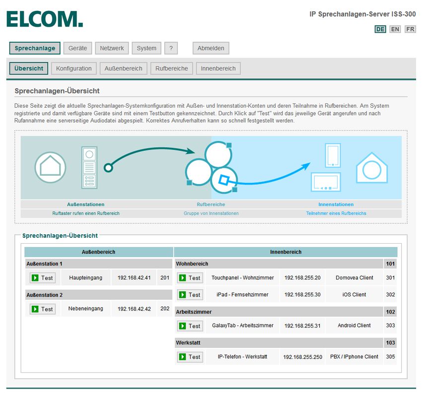
B1.            Beschreibung Sprechanlagen-Systemübersicht
               Description of the voice system overview · Description de la vue d‘ensemble du système d‘interphone
                                                                                                                                INSTALLATION
                                                                                                                                Dokument: Version 2.2   Datum: 11.07.2015

 M                Sprechanlage       Übersicht                   Intercom         Overview                    Interphone          Vue d‘ensemble

                                                                                                        Die Sprechanlagen-Übersicht ist die zentrale
                                                                                                        Statusseite zur laufenden Installation und zeigt
                                                                                                        konfigurierte und verfügbare Geräte.

                                                                                                        Werkseitig sind:
                                                                                                        1 Video-Außenstation
                                                                                                        1 Rufbereich (= 1 Ruftaster) mit
                                                                                                        3 Beispiel-Innenstationen (Clients)
                                                                                                        vordefiniert.

                                                                                                        The intercom overview is the central status page for
                                                                                                        the running installation and shows the devices that
                                                                                                        are configured and available.

                                                                                                        The following are predefined at the factory:
                                                                                                        1 outdoor video station
                                                                                                        1 call zone (= 1 call button) with
                                                                                                        3 example indoor stations (clients)

                                                                                                        La vue d‘ensemble d‘interphone constitue le masque
                                                                                                        d‘état central de l‘installation en cours et affiche les
                                                                                                        appareils configurés et disponibles.

                                                                                                        Sont prédéfinis en usine :
                                                                                                        1 poste vidéo extérieur
                                                                                                        1 zone d‘appel (= 1 bouton d‘appel) avec
                                                                                                        3 postes intérieurs modèles (clients)

www.elcom.de                                                                                                                                                                9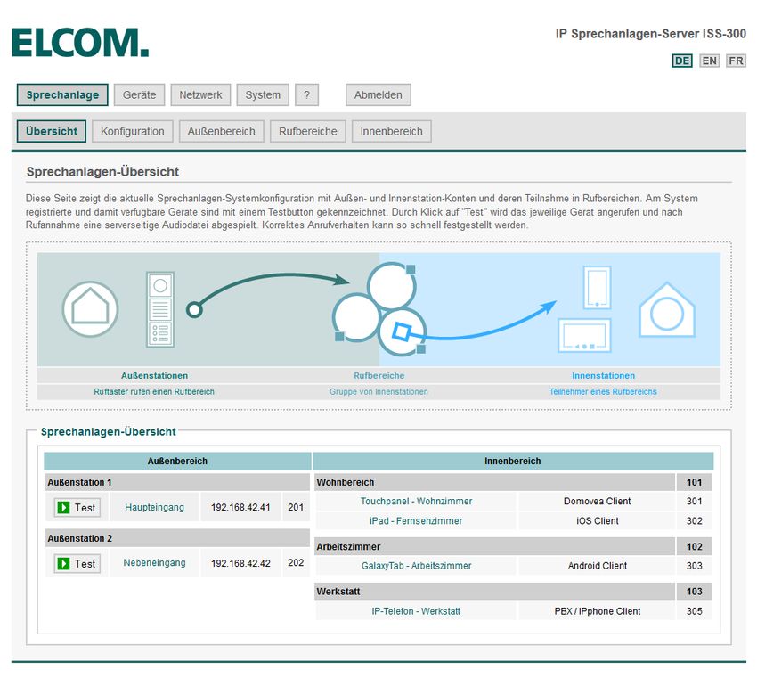
B2.   Konfigurationsvorlage definieren
      Defining the configuration template · Définition du modèle de configuration
                                                                                                                  INSTALLATION
                                                                                                                  Dokument: Version 2.2   Datum: 11.07.2015

 M       Sprechanlage      Konfiguration                  Intercom        Configuration         Interphone            Configuration

                                                                                          Mit dem Konfigurations-Generator wird die tatsäch-
                                                                                          liche Sprechanlagen-Konfiguration weitgehend
                                                                                          vordefiniert. Dabei werden notwendige Außenstati-
                                                                                          onen und Rufbereiche mit Beispiel-Innenstationen
                                                                                          (Clients) angelegt.
                                                                                          Bitte beachten: Anzahl der Rufbereiche heißt nicht
                                                                                          automatisch Anzahl Ruftaster an der Außenstation.
                                                                                          Sind pro Außenstation verschiedene Ziele zu rufen,
                                                                                          wird hier die Gesamtzahl der Rufbereiche angeben.

                                                                                          Most of the definition of the actual intercom configu-
                                                                                          ration is done in advance with the configuration gene-
                                                                                          rator. The outdoor stations and call zones needed are
                                                                                          created with example indoor stations (clients).
                                                                                          Please note: The number of call zones is not au-
                                                                                          tomatically equal to the number of call buttons on
                                                                                          the outdoor station. If each outdoor station can call
                                                                                          different destinations, the total number of call zones is
                                                                                          specified here.

                                                                                          Le générateur de configuration permet de prédéfinir
                                                                                          l‘essentiel de la configuration de l‘interphone. Les
                                                                                          postes extérieurs et zones d‘appels avec postes intéri-
                                                                                          eurs modèles (clients) sont créés lors de ce processus.
                                                                                          Veuillez noter : Le nombre de zones d‘appel ne cor-
                                                                                          respond pas nécessairement au nombre de boutons
                                                                                          d‘appel sur le poste extérieur. Si différents destina-
                                                                                          taires doivent être appelés par poste extérieur, le
                                                                                          nombre total de zones d‘appel est indiqué ici.

10                                                                                                                                         www.elcom.de
B2. Konfigurationsvorlage definieren
Defining the configuration template · Définition du modèle de configuration
INSTALLATION
Dokument: Version 2.2 Datum: 11.07.2015
M Sprechanlage Übersicht Intercom Overview Interphone Vue d‘ensemble
Im Beispiel wurden:
- 2 Außenstationen mit 3 gleich belegten Ruftastern
- 3 Rufbereiche (= 3 Rufziele im System) mit
- 3 Beispiel-Innenstationen pro Rufbereich
angenommen.
Nach dem „Generieren“-Prozess werden diese An-
gaben in der Sprechanlagen-Übersicht angezeigt.
The example assumes the following:
- 2 outdoor stations with 3 identically configured call
buttons
- 3 call zones (= 3 call destinations in the system) with
- 3 example indoor stations per call zone
After the „generation“ process, this information is
shown in the intercom overview.
Supposons que dans l‘exemple on dispose de :
- 2 postes extérieurs avec 3 boutons d‘appels à
affectation identique
- 3 zones d‘appel (= 3 destinataires d‘appel dans
le système) avec
- 3 postes d‘intérieur modèles par zone d‘appel
Après le processus de « Création », ces données
s‘affichent dans la vue d‘ensemble d‘interphone.
www.elcom.de 11B3. Konfiguration anpassen - Außenbereich
Adapting the configuration - outdoor area · Adaptation de la configuration - espace extérieur
INSTALLATION
Dokument: Version 2.2 Datum: 11.07.2015
M Sprechanlage Außenbereich Intercom Outdoor Interphone Extérieur
Im nächsten Schritt wird die Konfiguration persona-
lisiert. Dabei sind für die einzelnen Außenstationen
aussagekräftige Namen zu vergeben.
Klicken Sie auf den „Bearbeiten“-Button.
The configuration is customised in the next step. Me-
aningful names should be assigned to the individual
outdoor stations.
Click the „Edit“ button.
Lors de la prochaine étape, la configuration est
personnalisée. Lors de ce processus, il convient
d‘attribuer des noms pertinents aux postes extérieurs.
Cliquez sur le bouton « Éditer ».
12 www.elcom.deB3. Konfiguration anpassen - Außenbereich
Adapting the configuration - outdoor area · Adaptation de la configuration - espace extérieur
INSTALLATION
Dokument: Version 2.2 Datum: 11.07.2015
M Sprechanlage Außenbereich Intercom Outdoor Interphone Extérieur
Vergeben Sie für jede Außenstation einen Namen.
Dieser wird dann bei einem Anruf im Display der
Videofon-Clients und IP Telefone angezeigt:
Eingehender Anruf von z.B. „Haupteingang“.
Editieren Sie das Eingabefeld „Anzeigename“ und
bestätigen Sie die Eingabe mit „Speichern“. Bearbei-
ten Sie alle weiteren Außenstationen entsprechend.
Assign a name to each outdoor station. This is then
shown in the display of the video phone client and IP
telephones during a call:
Incoming call from e.g. „Main entrance“.
Edit the input field „Display name“ and confirm the
input with „Save“. Edit all the other outdoor stations
accordingly.
Attribuez un nom à chaque poste extérieur. Celui-ci
s‘affiche alors lors de l‘ouverture des clients Vidéo-
phone et téléphones IP à l‘écran :
Appel entrant, par ex. depuis « Entrée principale ».
Éditez le champ de saisie « Nom d‘affichage » et con-
firmez l‘entrée par « Enregistrer ». Éditez de la même
manière l‘ensemble des postes extérieurs.
www.elcom.de 13B3. Konfiguration anpassen - Außenbereich
Adapting the configuration - outdoor area · Adaptation de la configuration - espace extérieur
INSTALLATION
Dokument: Version 2.2 Datum: 11.07.2015
M Sprechanlage Außenbereich Intercom Outdoor Interphone Extérieur
Beide Außenstationen sind nun mit den Anzei-
genamen versehen.
Im nächsten Schritt erfolgt die Anpassung
der Rufbereiche.
Both outdoor stations are now assigned display
names.
In the next step, the call zones will be customised.
Les deux postes extérieurs disposent à présent des
noms d‘affichage.
Lors de la prochaine étape, il convient d‘adapter
les zones d‘appel.
14 www.elcom.deB4. Konfiguration anpassen - Außenbereich
Adapting the configuration - outdoor area · Adaptation de la configuration - espace extérieur
INSTALLATION
Dokument: Version 2.2 Datum: 11.07.2015
M Sprechanlage Rufbereiche Intercom Call Zones Interphone Zones d‘appel
Die Rufbereiche repräsentieren in der Regel ein
Ruftaster-Ziel der Außenstation. Jeder Rufbereich
kann eine oder mehrere Innenstationen enthalten.
Die Innenstationen eines Rufbereichs können sich
gegenseitig anrufen. Sollen Geräte verschiedener
Rufbereiche miteinander kommunizieren, ist dafür
ein zusätzlicher (Intern-)Rufbereich hinzuzufügen.
Mit „Bearbeiten“ vergeben Sie für jeden Rufbereich
eine aussagekräftige Bezeichnung.
The call zones generally represent a call button
destination for the outdoor station. Each call zone
can include one or more indoor stations. The indoor
stations for a call zone can call one another. Should
devices from different call zones also communicate
with one another, an additional (internal) call zone
must be added for this purpose.
With „Edit“, assign a meaningful name for each call
zone.
Les zones d‘appel correspondent généralement au
destinataire du bouton d‘appel du poste extérieur.
Chaque zone d‘appel peut comprendre un ou plu-
sieurs postes intérieurs. Les postes intérieurs d‘une
zone d‘appel peuvent s‘appeler mutuellement. Si des
appareils de différentes zones d‘appel doivent com-
muniquer, il convient d‘ajouter à cet effet une zone
d‘appel (interne) supplémentaire.
La fonction « Éditer » permet d‘attribuer à chaque
zone d‘appel une désignation pertinente.
www.elcom.de 15B4. Konfiguration anpassen - Rufbereiche
Adapting the configuration - call zones · Adaptation de la configuration - zones d‘appel
INSTALLATION
Dokument: Version 2.2 Datum: 11.07.2015
M Sprechanlage Rufbereiche Intercom Call Zones Interphone Zones d‘appel
Editieren Sie das Eingabefeld „Rufbereich-Be-
zeichnung“ und bestätigen Sie die Eingabe mit
„Speichern“.
Bearbeiten Sie alle weiteren Rufbereiche ent-
sprechend.
Edit the input field „Call zone name“ and confirm
the input with „Save“.
Edit all the other call zones accordingly.
Éditez le champ de saisie « Désignation de zone
d‘appel » et confirmez l‘entrée par « Enregistrer ».
Éditez de la même manière l‘ensemble des zones
d‘appels.
16 www.elcom.deB4. Konfiguration anpassen - Rufbereiche
Adapting the configuration - call zones · Adaptation de la configuration - zones d‘appel
INSTALLATION
Dokument: Version 2.2 Datum: 11.07.2015
M Sprechanlage Rufbereiche Intercom Call Zones Interphone Zones d‘appel
Alle drei Rufbereiche sind nun mit Bezeichnungen
versehen.
Im nächsten Schritt erfolgt nun die Anpassung
der Innenstationen.
All three call zones are now provided with names.
In the next step, the indoor stations will be custo-
mised.
Les trois zones d‘appels disposent à présent de dési-
gnations.
Lors de la prochaine étape, il convient d‘adapter les
postes intérieurs.
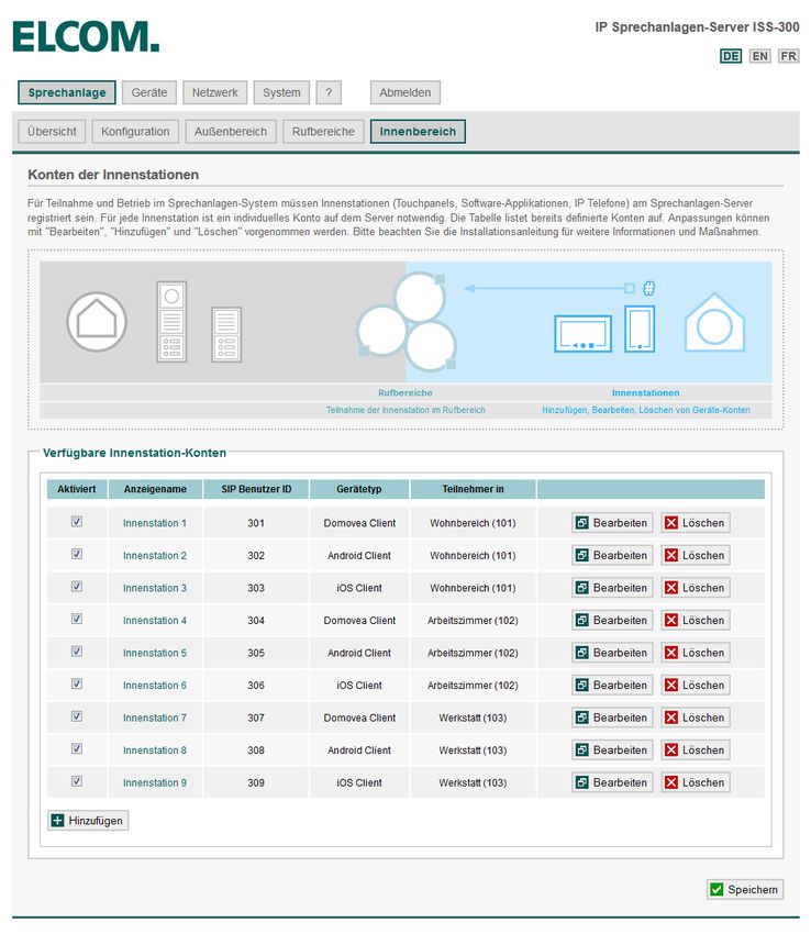
www.elcom.de 17B5. Konfiguration anpassen - Innenbereich
Adapting the configuration - indoor area · Adaptation de la configuration - espace intérieur
INSTALLATION
Dokument: Version 2.2 Datum: 11.07.2015
M Sprechanlage Innenbereich Intercom Indoor Interphone Intérieur
Beim Generieren der Konfiguration werden pro
Rufbereich zwei Beispiel-Innenstationen angelegt.
Dies dient lediglich zum besseren Verständnis und
entspricht natürlich nicht den tatsächlichen Gege-
benheiten. „Löschen“ Sie am besten zuerst nicht
benötigte Definitionen und bestätigen Sie dies mit
„Speichern“. Mit „Bearbeiten“ wird dann der tat-
sächliche Gerätetyp und Anzeigename festgelegt.
Über „Hinzufügen“ können weitere Innenstationen
angelegt werden.
When generating the configuration, two example
indoor stations are created for each call zone. These
are only for better understanding, and of course do
not correspond to the actual situation.
It is best to „Delete“ any definitions not needed and
confirm that with „Save“. Then use „Edit“ to specify
the actual device type and display name. The „Add“
button can be used to create additional indoor sta-
tions.
Lors de la création de la configuration, deux postes
intérieurs modèles sont générés par zone d‘appel. Ils
servent uniquement à faciliter la compréhension et ne
correspondent naturellement pas aux conditions réel-
les. Nous vous recommandons de supprimer d‘abord
les définitions dont vous n‘avez pas besoin, puis de
confirmer la suppression par « Enregistrer ». « Éditer
» vous permet ensuite de définit le type d‘appareil
et le nom d‘affichage réels. « Ajouter » vous permet
d‘ajouter des postes intérieurs supplémentaires.
18 www.elcom.deB5. Konfiguration anpassen - Innenbereich
Adapting the configuration - indoor area · Adaptation de la configuration - espace intérieur
INSTALLATION
Dokument: Version 2.2 Datum: 11.07.2015
M Sprechanlage Innenbereich Intercom Indoor Interphone Intérieur
Zuerst wird der Gerätetyp der Innenstation gewählt:
„Android/iOS/Windows“ beschreiben Einstellungen
für die ELCOM Videofon-Clients. „Domovea“ für
die Türkommunikations-Applikation in der Hager
Domovea-Visualisierung. „PBX/IP-Phone“ für die
Anbindung von gängigen Telefonanlagen oder IP
Hardware-Telefonen. „Benutzerdefiniert“ ermög-
licht die individuelle Angabe notwendiger SIP-
und DTMF-Parameter.
First, select the device type of the indoor station:
„Android/iOS/Windows“ describes settings for the
ELCOM video phone clients. „Domovea“ is for the
door communications application in the Hager Do-
movea visualization program. „PBX/IP phone“ is for
the connection of current telephone systems or IP
hardware telephones. „User-defined“ makes it possi-
ble to custom-specify any SIP and DTMF parameters
needed.
Sélectionnez d‘abord le type d‘appareil du poste
intérieur:
« Android/iOS/Windows » décrit les paramètres pour
les clients Vidéophone ELCOM. « Domovea » corres-
pond à l‘application de communication de porte de la
visualisation Domovea Hager. « PBX/IP-Phone » sert
à la connexion de standards téléphoniques classiques
ou de téléphones IP matériels. « Personnalisé » per-
met la saisie individuelle des paramètres SIP et DTMF
nécessaires.
www.elcom.de 19B5. Konfiguration anpassen - Innenbereich
Adapting the configuration - indoor area · Adaptation de la configuration - espace intérieur
INSTALLATION
Dokument: Version 2.2 Datum: 11.07.2015
M Sprechanlage Innenbereich Intercom Indoor Interphone Intérieur
Nun ist ein aussagekräftiger „Anzeigename“ anzu-
geben. Dieser dient der Auswahl bei automatischer
Konfiguration und der Namensanzeige bei Internru-
fen. Wählen Sie in sicheres Passwort, z.B. beim Be-
trieb in öffentlichen Bereichen. Bestimmen Sie wel-
chen Rufbereichen die Innenstation zugeordnet sein
soll. Hier ist auch eine Mehrfachauswahl möglich:
z.B. wenn die Innenstation auf mehrere Ruftaster
reagieren soll oder eine Intern-Rufbereich gebildet
wurde. „Speichern“ übernimmt die Einstellungen.
Now assign a meaningful „Display name“. This will
be used for selections in automatic configuration
and name displays in internal calls. Select a secure
password, for example for operation in public areas.
Specify which call zones should be assigned to the
indoor station. Multiple selections are also possible:
for example, when the indoor station should react to
several call buttons or an internal call zone is defined.
„Save“ saves the settings.
Il convient ensuite de saisir un « Nom d‘affichage »
pertinent. Celui-ci sert au choix lors de la configurati-
on automatique et de l‘affichage du nom lors d‘appels
internes. Sélectionnez un mot de passe sécurisé, par
ex. lors de l‘utilisation dans les espaces accessibles
au public. Définissez les zones d‘appel auxquelles
le poste intérieur doit être affecté. Ici, vous pouvez
procéder à un choix multiple : par ex. si le poste inté-
rieur doit réagir à plusieurs boutons d‘appel ou si une
zone d‘appel interne a été constituée. « Enregistrer »
permet d‘appliquer les réglages.
20 www.elcom.deB5. Konfiguration anpassen - Innenbereich
Adapting the configuration - indoor area · Adaptation de la configuration - espace intérieur
INSTALLATION
Dokument: Version 2.2 Datum: 11.07.2015
M Sprechanlage Innenbereich Intercom Indoor Interphone Intérieur
Alle nicht notwendigen Innenstation-Definitionen
wurden gelöscht, benötigte Definitionen auf den
richtigen Typ eingestellt und mit aussagekräftigen
Anzeigenamen versehen.
Damit ist die System-Konfiguration
abgeschlossen.
Any unnecessary indoor station definitions have been
deleted, all definitions needed have been set to the
correct type and assigned meaningful display names.
The system configuration is now complete.
Toutes les définitions de postes intérieurs inutiles sont
supprimées, les définitions nécessaires réglées pour
le type correspondant et pourvues de nom d‘affichage
pertinent.
La configuration du système est alors terminée.
www.elcom.de 21B6. Sprechanlagen-Systemübersicht prüfen
Checking the intercom system overview · Contrôler la vue d‘ensemble d‘interphone
INSTALLATION
Dokument: Version 2.2 Datum: 11.07.2015
M Sprechanlage Übersicht Intercom Overview Interphone Vue d‘ensemble
In der Sprechanlagen-Übersicht wird nun die
vollständige Konfiguration mit Bezeichnungen
und Rufbereich-Zuweisungen angezeigt.
Im nächsten Schritt erfolgt die Anpassung der
Außenstationen auf die System-Konfiguration.
In the intercom overview, the complete configuration
is now shown with names and call zone assignments.
In the next step, we will adapt the outdoor stations
to the system configuration.
La vue d‘ensemble d‘interphone affiche à présent la
configuration complète avec désignations et affecta-
tions des zones d‘appels.
Lors de la prochaine étape, les postes extérieurs
sont adaptés à la configuration du système.
22 www.elcom.deC1. Zweite Außeneinheit mit Subnetz verbinden
Connecting the second outdoor unit to the subnet · Connexion du second module extérieur au sous-réseau
INSTALLATION
Dokument: Version 2.2 Datum: 11.07.2015
Verbinden Sie nun zunächst die „zweite“ Außensta-
tion-Einheit (in unserem Beispiel: „Nebeneingang“)
mit dem Subnetz-Switch.
Überprüfen Sie vorher, ob die Ruftaster richtig ange-
SUBNET MAINNET schlossen sind. Das gilt insbesondere dann, wenn
von der jeweiligen Außenstation verschiedene Ruf-
bereiche anzurufen sind.
Die werkseitige Konfiguration lautet: Ruftaster an Z1
ruft 101, Z2 ruft 102, Z3 ruft 103 und Z4 ruft 104.
First, connect the „second“ outdoor station unit (in
our example „Side entrance“) to the subnet switch.
Check beforehand that the call buttons are connected
correctly. This is particularly important when different
call zones must be called from each outdoor station.
The factory configuration is as follows: Call button on
Z1 calls 101, Z2 calls 102, Z3 calls 103 and Z4 calls 104.
ISS-300
Connectez d‘abord le « second » module de poste ex-
térieur (dans le présent exemple : « Entrée secondaire »)
!
au switch de sous-réseau.
Contrôlez préalablement si les boutons d‘appel sont
#2 correctement branchés. Cela s‘applique notamment
lorsque le poste extérieur respectif permet d‘appeler
différentes zones d‘appel.
La configuration d‘usine se présente comme suit : Le
bouton d‘appel de Z1 appelle 101, Z2 appelle 102, Z3
appelle 103 et Z4 appelle 104.
Hinweise / Notes / Notes
Beginnen Sie immer mit der letzten Außenstation (bei bis zu 4) und Always start with the last outdoor station (for up to 4) and carry out Commencez toujours par le dernier poste extérieur (jusqu‘à 4) et effectu-
führen die nächsten Schritte entsprechend der Außenstations-Num- the next steps in order of the outdoor station number. Instructions for ez les prochaines étapes en fonction du numéro du poste extérieur. Vous
mer durch. Hinweise zur Installation von mehr als 4 Eingängen finden the installation of more than 4 entrances can be found in the detailed trouverez des remarques pour l‘installation de plus de 4 entrées dans la
Sie in den erweiterten Anleitungen. instructions. notice étendue.
www.elcom.de 23C1. Zweite Außeneinheit mit Subnetz verbinden
Connecting the second outdoor unit to the subnet · Connexion du second module extérieur au sous-réseau
INSTALLATION
Dokument: Version 2.2 Datum: 11.07.2015
M Sprechanlage Übersicht Intercom Overview Interphone Vue d‘ensemble
Haben Sie etwas Geduld. Das Hochfahren von Tür-
lautsprecher-Modul und Kamera dauert etwa eine
Minute. Schließen Sie in dieser Zeit keine weiteren
(falls mehrere) Außenstationen an.
Ist die Außenstation am System angemeldet, dann
erscheint ein „Test“-Button in der Übersicht.
Die im Augenblick als Haupteingang (1. Eingang)
angemeldete Außenstation muss nun als Neben-
eingang (2. Eingang) definiert werden.
Have some patience. It takes about a minute for the
door speaker module and camera to boot up. During
this time, do not connect any other outdoor stations
(if there are more). Once the outdoor station is regis-
tered in the system, a „Test“ button will appear in the
overview.
The outdoor station currently registered as the main
entrance (entrance 1) must now be defined as the
side entrance (entrance 2).
! Veuillez patienter. Le démarrage du module de haut-
parleur de porte et de la caméra prend environ une
minute. Ne connectez pas d‘autres postes extérieurs
(le cas échéant) pendant ce démarrage.
Lorsque le poste extérieur est connecté au système,
un bouton « Test » s‘affiche dans la vue d‘ensemble.
Le poste extérieur connecté actuellement comme
entrée principale (1ère entrée) doit alors être définie
comme entrée secondaire (2ème entrée).
24 www.elcom.deC2. IP Türlautsprecher der Einheit konfigurieren
Configuring IP door speakers in the unit · Configuration du haut-parleur de porte IP du module
INSTALLATION
Dokument: Version 2.2 Datum: 11.07.2015
M Geräte Außeneinheiten Devices Outdoor Units Appareils Unités extérieures
Werkseitig sind die Komponenten immer auf
Außenstation 1 eingestellt. Das heißt, Sie haben
sofort und ohne weitere PC-Umstellungen einen
Zugriff auf die Geräte.
Wechseln Sie in das Menü: „Geräte/Außeneinhei-
ten“. Hier sehen Sie eine Zusammenfassung der
verfügbaren Außeneinheiten mit ihren Geräte-Zu-
ordnungen.
Klicken Sie auf: „IP Türlautsprecher-Modul 1“
Components are always configured as outdoor stati-
on 1 at the factory. That allows you to have immediate
access to the device without additional PC configura-
tion.
Switch to the menu: „Devices / outdoor units“. Here,
you see a summary of the outdoor units available,
with their device assignments.
Click on: „IP door speaker module 1“
Par défaut, les éléments sont toujours réglés pour le
poste extérieur 1. C‘est-à-dire que vous avez immé-
diatement et sans reparamétrage PC supplémentaire
accès aux appareils.
Commutez vers le menu : « Appareils/modules
extérieurs ». Vous trouverez ici un résumé des mo-
dules extérieurs disponibles et de leurs affectations
d‘appareils.
Cliquez sur: « Module de haut-parleur de porte IP 1 »
www.elcom.de 25C2. IP Türlautsprecher der Einheit konfigurieren
Configuring IP door speakers in the unit · Configuration du haut-parleur de porte IP du module
INSTALLATION
Dokument: Version 2.2 Datum: 11.07.2015
M Geräte IP Geräte Devices IP Devices Appareils Appareils IP
Sie gelangen nun zur konfigurationstechnischen Zu-
sammenfassung des „IP Türlautsprecher-Modul 1“.
Wenn Sie aus dem Hauptnetz (Heim-/Firmennetz)
auf das System zugreifen, ist der entsprechende
Weiterleitungs-Link aktiv. Beim Zugriff aus dem
Sprechanlagen-Subnetz ist die direkte Geräte
IP-Adresse aktiv. Außerdem wird das werkseitige
Geräte-Passwort angezeigt.
Klicken Sie auf den jeweils aktiven Geräte-Link.
You are now taken to the configuration summary of
„IP door speaker module 1“.
If you access the system from the main network
(home/company network), the corresponding forwar-
ding link is active. On access from the intercom sub-
net, the direct development IP address is active. The
factory-assigned device password is also displayed.
Click the active device link.
Vous accédez alors au résumé de configuration du «
Module de haut-parleur de porte IP 1 ».
Si vous accédez au système depuis le réseau principal
(réseau domestique/d‘entreprise), le lien de transmis-
sion correspondant est actif. Lors de l‘accès depuis
le sous-réseau d‘interphone, l‘adresse IP directe de
l‘appareil est active. De plus, le mot de passe attribué
en usine à l‘appareil s‘affiche.
Cliquez sur le lien d‘appareil actif respectif.
26 www.elcom.deC2. IP Türlautsprecher der Einheit konfigurieren
Configuring IP door speakers in the unit · Configuration du haut-parleur de porte IP du module
INSTALLATION
Dokument: Version 2.2 Datum: 11.07.2015
Die Konfigurations-Oberfläche des Türlautsprechers
wird in einem neuen Browsertab geöffnet.
Wählen Sie das „Quickstart“-Menü aus und geben
Sie das Passwort (werkseitig: 1234) ein.
Das Modul ist für Standard-Anwendungen optimal
vorkonfiguriert. Über die folgenden Schritte hinaus-
gehende Änderungen sind in der Regel nicht not-
wendig. Die Einstellungen in der „Experten-Konfigu-
ration“ sollten keinesfalls geändert werden.
The configuration user interface for the door speaker
opens in a new browser tab.
Select the „Quick start“ menu and enter the password
(factory setting: 1234).
The module is preconfigured for standard applica-
tions. Changes in addition to the following steps are
generally not necessary. The settings in the „expert
configuration“ should under no circumstances be
changed.
L‘interface de configuration du haut-parleur de porte
s‘affiche dans un nouvel onglet de navigateur.
Sélectionnez le menu « Quickstart » et saisissez le
mot de passe (par défaut : 1234).
Le module est préconfiguré de manière optimale pour
! les applications standard. Au-delà des étapes suivan-
tes, aucune modification n‘est généralement néces-
saire. Les réglages dans la « Configuration Expert »
ne doivent être modifiés en aucun cas.
Hinweise / Notes / Notes
Die Konfigurationsoberfläche wird vollständig in den Browser-Spei- The configuration user interface is completely loaded in the browser L‘interface de configuration est chargée entièrement dans la mémoire du
cher geladen. Der Aufruf kann etwas dauern. Den Webseiten-Link zur cache. It can take some time to call it up. You can find the web page link navigateur. L‘ouverture peut prendre un certain temps. Vous trouverez le
IP Türlautsprecher-Anleitung finden Sie unter „Hilfe“. to the IP speaker instructions under „Help“. lien vers le site Internet de la notice du haut-parleur de porte IP dans la
rubrique « Aide ».
www.elcom.de 27C2. IP Türlautsprecher der Einheit konfigurieren
Configuring IP door speakers in the unit · Configuration du haut-parleur de porte IP du module
INSTALLATION
Dokument: Version 2.2 Datum: 11.07.2015
Das Türlautsprecher-Modul wird jetzt über die Aus-
wahl von „Eingang 2“ und „3 Ruftaster“ auf eine
zweite Außenstation (hier: Nebeneingang) mit 3 Ruf-
!
tastern eingestellt.
Die Einstellung wird mit „Speichern“ übernommen.
!
Sobald der Button „Gespeichert“ anzeigt, ist der
Vorgang abgeschlossen. Der Browsertab kann nun
geschlossen werden. Das IP Türlautsprecher-Modul
ist damit auf „Eingang 2“ umgestellt.
The door speaker module is now configured by se-
lecting „Entrance 2“ and „3 call buttons“ to make it
a second outdoor station (here, the side entry) with 3
call buttons.
Save the settings with „Save“. Once the „Saved“ but-
ton appears, the process is complete. The browser
tab can now be closed. The IP door speaker module
is set to „Entrance 2“.
Le module de haut-parleur de porte est à présent
réglé via la sélection de « Entrée 2 » et « 3 boutons
d‘appel » pour un second poste extérieur (ici : entrée
secondaire) avec 3 boutons d‘appel.
Le réglage est appliqué par « Enregistrer ». Dès que
le bouton « Enregistré » s‘affiche, le processus est ter-
miné. Vous pouvez alors fermer l‘onglet de navigateur.
À présent, le module de haut-parleur de porte IP est
réglé sur « entrée 2 ».
Hinweise / Notes / Notes
Wenn Sie das Gerätepasswort ändern, dann aktualisieren Sie bitte If you change the device password, then please also update the entry Si vous modifiez le mot de passe d‘appareil, vous devez aussi adapter
auch den Eintrag im Sprechanlagen-Server unter: „Geräte / IP Geräte / in the intercom server under: „Devices / IP devices / Edit“. Then you will l‘entrée dans le serveur d‘interphone sous : « Appareils / Appareils IP /
Bearbeiten“. So haben Sie das Passwort bei einem späteren Service have the password easily at hand during later service. Éditer ». Ainsi, vous pouvez accéder rapidement au mot de passe en cas
schnell zur Hand. de maintenance ultérieure.
28 www.elcom.deC3. IP Kamera-Modul der Einheit konfigurieren
Configuring the IP camera module of the unit · Configuration du module de caméra IP du module
INSTALLATION
Dokument: Version 2.2 Datum: 11.07.2015
M Geräte Außeneinheiten Devices Outdoor Units Appareils Unités extérieures
Gehen Sie in der Sprechanlagen-Server-Konfigura-
tion zurück auf die Übersicht: „Geräte/Außeneinhei-
ten“.
Klicken Sie hier auf den Link: „IP Kamera-Modul 1“.
In the intercom server configuration, go back to the
overview: „Devices / outdoor units“.
Click on the link: „IP camera module 1“.
Dans la configuration de serveur d‘interphone,
revenez à la vue d‘ensemble : « Appareils/modules
extérieurs ».
Cliquez ici sur le lien : « Module de caméra IP 1 »
www.elcom.de 29C3. IP Kamera-Modul der Einheit konfigurieren
Configuring the IP camera module of the unit · Configuration du module de caméra IP du module
INSTALLATION
Dokument: Version 2.2 Datum: 11.07.2015
M Geräte IP Geräte Devices IP Devices Appareils Appareils IP
Sie sehen hier die konfigurationstechnische Zusam-
menfassung zum „IP Kamera-Modul 1“.
Wenn Sie aus dem Hauptnetz (Heim-/Firmennetz)
auf das System zugreifen, ist der entsprechende
Weiterleitungs-Link aktiv, beim Zugriff aus dem
Sprechanlagen-Subnetz die direkte Geräte IP-Ad-
resse. Außerdem werden der werkseitige Benutzer-
name und das Geräte-Passwort angezeigt.
Klicken Sie auf den jeweils aktiven Geräte-Link.
Here, you see the configuration summary for „IP ca-
mera module 1“.
If you access the system from the main network
(home/company network), the corresponding forwar-
ding link is active. When accessing from the intercom
subnet, the direct device IP address is active. The
factory-configured user name and device password
are also shown. Click the active device link.
Vous y trouverez le résumé de la configuration du «
Module de caméra IP 1 »
Si vous accédez au système depuis le réseau principal
(réseau domestique/d‘entreprise), le lien de transmis-
sion correspondant est actif. Si vous accédez depuis
le sous-réseau d‘interphone, l‘adresse d‘appareil IP
directe est active. De plus, le nom d‘utilisateur d‘usine
et le mot de passe d‘appareil s‘affichent.
Cliquez sur le lien d‘appareil actif respectif.
30 www.elcom.deC3. IP Kamera-Modul der Einheit konfigurieren
Configuring the IP camera module of the unit · Configuration du module de caméra IP du module
INSTALLATION
Dokument: Version 2.2 Datum: 11.07.2015
Die Konfigurationsoberfläche der Kamera wird in
einem neuen Browsertab geöffnet.
Wählen Sie das „Quickstart“-Menü aus und geben
Sie den Benutzernamen und das Passwort (werk-
seitig: admin/1234) ein.
Das Modul ist für Standardanwendungen optimal
vorkonfiguriert. Die Einstellungen in der Experten-
Konfiguration sollten keinesfalls geändert werden.
The configuration user interface for the camera
opens in a new browser tab.
Select the „Quick start“ menu and enter the userna-
me and password (factory settings: admin/1234).
The module is preconfigured for standard applica-
tions. The settings in the expert configuration should
under no circumstances be changed.
L‘interface de configuration de la caméra s‘affiche
dans un nouvel onglet de navigateur.
Sélectionnez le menu « Quickstart » et saisissez le
nom d‘utilisateur et le mot de passe (par défaut :
admin / 1234).
Le module est préconfiguré de manière optimale pour
les applications standard. Les réglages dans la Con-
figuration Expert ne doivent être modifiés en aucun
cas.
Hinweise / Notes / Notes
Die Konfigurationsoberfläche wird vollständig in den Browser-Spei- The configuration user interface is completely loaded in the browser L‘interface de configuration est chargée entièrement dans la mémoire du
cher geladen. Der Aufruf kann etwas dauern. Den Webseiten-Link zur cache. It can take some time to call it up. You can find the web page link navigateur. L‘ouverture peut prendre un certain temps. Vous trouverez
IP Kamera-Anleitung finden Sie unter „Hilfe“. to the IP camera instructions under „Help“. le lien vers le site Internet de la notice de la caméra IP dans la rubrique
« Aide ».
www.elcom.de 31C3. IP Kamera-Modul der Einheit konfigurieren
Configuring the IP camera module of the unit · Configuration du module de caméra IP du module
INSTALLATION
Dokument: Version 2.2 Datum: 11.07.2015
Das Kamera-Modul wird über die Auswahl von z.B.
„Eingang 2“ auf die zweite Außenstation (hier: „Ne-
beneingang“) konfiguriert.
! Die Einstellung wird mit „Speichern“ übernommen.
Sobald der Button „Gespeichert“ anzeigt, ist der
Vorgang abgeschlossen. Der Browsertab kann nun
geschlossen werden. Das Modul ist nun auf „Eingang
2“ umgestellt.
The camera module is configured by selecting, for
example, „Entrance 2“ on the second outdoor station
(here, „Side entrance“).
Save the settings with „Save“. Once the „Saved“ but-
ton appears, the process is complete. The browser
tab can now be closed. The module is now converted
to „Entrance 2“.
Le module de caméra est configuré via la sélection de
par ex. « Entrée 2 » pour le second poste extérieur (ici :
« Entrée secondaire »).
Le réglage est appliqué par « Enregistrer ». Dès que le
bouton « Enregistré » s‘affiche, le processus est ter-
miné. Vous pouvez alors fermer l‘onglet de navigateur.
Le module est à présent reparamétré pour « Entrée 2 ».
Hinweise / Notes / Notes
Wenn Sie das Gerätepasswort ändern, dann aktualisieren Sie bit- If you change the device password, then please update the entry in the Si vous modifiez le mot de passe de l‘appareil, vous devez adapter
te den Eintrag im Sprechanlagen-Server unter: „Geräte / IP Geräte / intercom server under: „Devices / IP devices / Edit“. Then you will have l‘entrée dans le serveur d‘interphone sous : « Appareils / Appareils IP /
Bearbeiten“. So haben Sie das Passwort bei einem späteren Service the password easily at hand during later service. Éditer ». Ainsi, vous pouvez accéder rapidement au mot de passe en cas
schnell zur Hand. de maintenance ultérieure.
32 www.elcom.deC4. Erste Außeneinheit mit Subnetz verbinden
Connecting the first outdoor unit to the subnet · Connexion du premier module extérieur au sous-réseau
INSTALLATION
Dokument: Version 2.2 Datum: 11.07.2015
Verbinden Sie jetzt zusätzlich die „erste“ Außen-
station-Einheit (in unserem Beispiel der „Haupt-
eingang“) mit dem Subnetz-Switch.
Überprüfen Sie zuerst, ob alle Ruftaster richtig an-
SUBNET MAINNET geschlossen sind. Das gilt insbesondere, wenn von
der jeweiligen Außenstation verschiedene Rufberei-
che anzurufen sind.
Die werkseitige Konfiguration lautet: Ruftaster an Z1
ruft 101, Z2 ruft 102, Z3 ruft 103 und Z4 ruft 104.
Now also connect the „first“ outdoor station unit (in our
example the „Main entrance“) to the subnet switch.
Check beforehand that all the call buttons are con-
nected correctly. This is particularly important when
different call zones must be called from each outdoor
ISS-300 station.
The factory configuration is as follows: Call button on
#2 Z1 calls 101, Z2 calls 102, Z3 calls 103 and Z4 calls 104.
Connectez à présent aussi le « premier » module de
poste extérieur (dans le présent exemple : « Entrée
principale ») au switch de sous-réseau.
Contrôlez préalablement si les tous les boutons
!
d‘appel sont correctement branchés. Cela s‘applique
notamment lorsque le poste extérieur respectif per-
#1
met d‘appeler différentes zones d‘appel.
La configuration d‘usine se présente comme suit : Le
bouton d‘appel de Z1 appelle 101, Z2 appelle 102, Z3
appelle 103 et Z4 appelle 104.
Hinweise / Notes / Notes
Die bereits auf andere Eingänge konfigurierten Außenstationen blei- The outdoor stations already configured at other entrances remain Les postes extérieurs déjà configurés pour d‘autres entrées restent con-
ben angeschlossen. Es ist wichtig, das nicht mehrere „werkseinge- connected. It is important that more than one „factory-configured“ out- nectés Afin d‘éviter les conflits d‘adresses, il est important de ne pas
stellte“ Außenstationen gleichzeitig angeschlossen sind, da es sonst door station is not connected simultaneously, since this will result in IP connecter simultanément plusieurs postes extérieurs à « configuration
zu IP Adresskonflikten kommt. address conflicts. d‘usine ».
www.elcom.de 33C5. Sprechanlagen-Systemübersicht prüfen
Checking the intercom system overview · Contrôler la vue d‘ensemble d‘interphone
INSTALLATION
Dokument: Version 2.2 Datum: 11.07.2015
M Sprechanlage Übersicht Intercom Overview Interphone Vue d‘ensemble
Haben Sie auch hier etwas Geduld, bis die Außen-
station bei „Haupteingang“ mit dem „Test“-Button
als am System angemeldet erscheint.
Bei dieser Außenstation sind keine weiteren Einstel-
lungen notwendig. Als „Außenstation 1“ ist sie für
den „Haupteingang“ optimal konfiguriert.
Über den „Test“-Button können nun serverseitig
Anrufe durchgeführt werden, um das korrekte An-
rufverhalten der Außenstationen zu prüfen.
Have some patience here, until the outdoor station at
the „Main entrance“ appears registered in the system
with the „Test“ button.
No additional settings must be configured for this
outdoor system. As „Outdoor station 1“, it is already
perfectly configured for the „Main entrance“.
The „Test“ button can now be used to carry out calls
from the server to test the correct calling behaviour of
the outdoor stations.
Veuillez de nouveau patienter jusqu‘à ce que le poste
extérieur pour l‘« Entrée principale » s‘affiche avec le
bouton « Test » comme connecté au système.
Ce poste extérieur ne requiert aucun paramétrage
supplémentaire. En tant que « Poste extérieur 1 »,
il est configuré de manière optimale pour l‘« Entrée
principale ».
Le bouton « Test » permet à présent d‘effectuer des
appels par le serveur, afin de contrôler le comporte-
ment d‘appel correct des postes extérieurs.
34 www.elcom.deVous pouvez aussi lire