FIREPLACE - A&T PROJECT DEVELOPMENTS INC - A&T Project Developments Inc.
←
→
Transcription du contenu de la page
Si votre navigateur ne rend pas la page correctement, lisez s'il vous plaît le contenu de la page ci-dessous
FIREPLACE

                                 190

 A&T PROJECT DEVELOPMENTS INC.
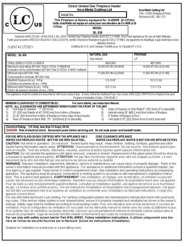
BL-936 / LANGLEY BUILDER’S LINEAR
15,500 BTU
Natural Gas & Propane
Installation and Operating Instructions
MODEL: BL-936
LANGLEY-36
CLIENT # LC773211
WARNING
IF THE INFORMATION IN THESE INSTRUCTIONS IS NOT FOLLOWED EXACTLY, A FIRE OR
EXPLOSION MAY RESULT CAUSING PROPERTY DAMAGE, PERSONAL INJURY, OR DEATH.
Do not store or use gasoline or other flammable vapors and liquids in the vicinity of this or
any other appliance.
WHAT TO DO IF YOU SMELL GAS:
Do not try to light any appliance
Do not touch any electrical switch; do not use any phone in your building
Immediately call your gas supplier from a neighbour’s phone. Follow gas supplier’s
instructions
If you cannot reach your gas supplier, call the fire department.
Installation and service must be performed by a qualified installer, service agency or gas
supplier.
WARNING: Improper installation, adjustment, alteration, services or maintenance can cause
injury or property damage. Refer to this manual. For assistance or additional information
consult a qualified installer, service agency or the gas supplier.
INSTALLER: Leave this manual with the appliance.
CONSUMER: Retain this manual for future reference.
PLEASE READ THIS MANUAL BEFORE
INSTALLING OR USING THIS APPLIANCE.
SAVE THIS MANUAL FOR FUTURE
REFERENCE.
A BARRIER DESIGNED TO REDUCE THE RISK OF
BURNS FROM THE HOT VIEWING GLASS IS
PROVIDED WITH THIS APPLIANCE AND SHALL BE
INSTALLED.
Page 1 of 53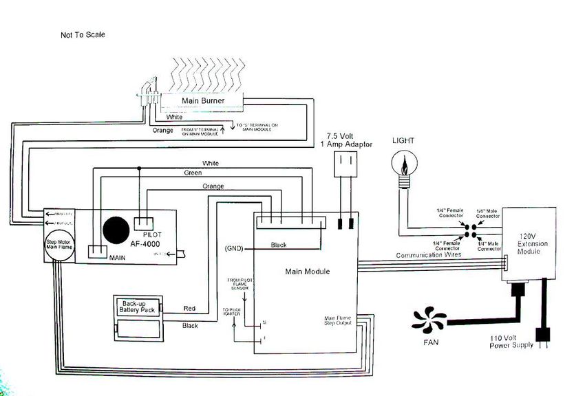
BL-936 / LANGLEY LINEAR BUILDER
15,500 BTU
GAZ NATUREL ET PROPANE
Manuel D’installation et Guide de l’utilisateur
MODEL: BL-936 /
LANGLEY-36 CLIENT # LC773211
AVERTISSEMENT
ASSUREZ-VOUS DE BIEN SUIVRE LES INSTRUCTIONS DONNÉES DANS CETTE NOTICE
POUR RÉDUIRE AU MINIMUM LE RISQUE D'INCENDIE OU D'EXPLOSION OU POUR ÉVITER
TOUT DOMMAGE MATÉRIEL, TOUTE BLESSURE OU LA MORT.
Ne pas entreposer ni utiliser d'essence ni d'autres vapeurs ou liquids inflammables dans le
voisinage de cet appareil ou de tout autre appareil.
QUE FAIRE SI VOUS SENTEZ UNE ODEUR DE GAZ:
Ne pas tenter d'allumer d'appareil.
Ne touchez à aucun interrupteur. Ne pas vous servir des telephones se trouvant dans le
bâtiment où vous vous trouvez.
Appelez immédiatement votre fournisseur de gaz depuis un voisin. Suivez les
instructions du fournisseur.
Si vous ne pouvez rejoindre le fournisseur de gaz, appelez le service des incendies.
L'installation et l'entretien doivent être assurés par un installateur ou un service d'entretien
qualifié ou par le fournisseur de gaz.
AVERTISSEMENT: Une mauvaise installation, de réglage, la modification, de services ou de
maintenance peut causer des dommages corporels ou matériels. Reportez-vous à ce manuel.
Pour toute assistance ou information supplémentaire, consulter un installateur qualifié, un
service ou le fournisseur de gaz.
INSTALLATEUR : Laissez cette notice avec
AVERTISSEMENT
l’appareil.
CONSOMMATEUR : Conservez cette notice pour
consultation ultérieure.
Une surface vitrée chaude
peut causer des brûlures.
S'IL VOUS PLAIT LIRE CE MANUEL AVANT Laisser refroidir la surface
D'INSTALLER OU UTILISER CET vitrée avant d’y toucher
APPAREIL. CONSERVEZ CE MANUEL
POUR REFERENCE FUTURE. Ne permettez jamais à un
enfant de toucher la
surface vitrée.
BARRIÈRE conçu pour réduire le
risque de brûlures et à la consultation
verre chaud EST FOURNI AVEC CET Page 2 of 53
APPAREIL ET DOIT SE.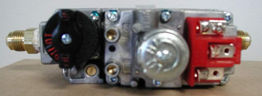
Table of Contents
IMPORTANT SAFETY INFORMATION …………………………………………………………….. 4 – 5

1.0   INTRODUCTION .....................................................................................................................
      1.1  Specifications, Appliance Dimensions & Installation Codes ................................. 6 - 7
      1.2  Features, Remote Control Functions .................................................................. 8 - 10
      1.3  Intended Use ............................................................................................................ 11
      1.4  General Safety.................................................................................................. 11 - 12

2.0   OPERATION ...........................................................................................................................
      2.1 Lighting Instructions ......................................................................................... 13 – 16
      2.2 Heat Output adjustment……………………………………………………………………17

3.0   INSTALLATION ......................................................................................................................
      3.1    Installation & Safety Notes ...................................................................................... 17
      3.2    Unpacking ................................................................................................................ 18
      3.3    Installation ............................................................................................................... 18
      3.3.1 Installing Non Combustible Board ............................................................................ 19
      3.3.2 Minimum Clearances & Non Combustible Material Requirements .......................... 20
      3.3.3 Gas Line Installation ................................................................................................ 21
      3.3.4 Thermostat,Wall Switch or Digital On/Off Remote………………………………..22 - 23
      3.3.5 Direct Vent Information .................................................................................... 23 - 29
      3.3.6 Glass Media Installation ........................................................................................... 30
      3.3.7 Door Installation and Safety Scren ................................................................... 30 – 32
      3.3.8 Initial Firing .............................................................................................................. 33
      3.3.9 Manifold Pressure..................................................................................................... 33
      3.3.10 Primary Air Adjustment .................................................................................... 33 - 34
      3.3.11 Altitude Adjustment .................................................................................................. 34
      3.3.12 Optional Fan Accessibility ........................................................................................ 35
      3.3.13 Gas Valve Access .................................................................................................... 36

4.0   MAINTENANCE .....................................................................................................................
      4.1  Maintenance Safety ................................................................................................. 37
      4.2  Recommended Service ........................................................................................... 37
      4.3  Glass Cleaning ........................................................................................................ 38
      4.4  Burner & Pilot Cleaning ........................................................................................... 38
      4.5  Valve & Pilot Replacement ............................................................................. 38 - 39

5.0   TROUBLE SHOOTING ……………………………………………………………….……. 40 - 43

6.0   REPLACEMENT PARTS ………………………………………………………………………...44

7.0   WARRANTY .………………………………………………………………………………....45 - 47

8.0   LABEL INFORMATION .………………………………………………………………….…48 - 49
APPENDIX A (INTERMITTENT PILOT & VALVE KIT)……………………....………………….50 - 53

                                                                                                                          Page 3 of 53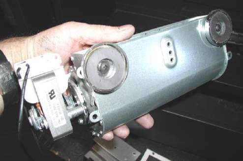
WARNING
Read this owner’s manual carefully and completely before trying to assemble, operate or
service this fireplace. Follow instructions for proper installation
Failure to install this appliance per the manufacturer’s instructions or failure to use only parts
specifically approved with this appliance may result in property damage or personal injury. Any
change to this fireplace or its controls can be dangerous.
Improper installation or use of this fireplace can cause serious injury or death from fire, burns,
explosions, electrical shock and carbon monoxide poisoning.
AVERTISSEMENT
• Lisez ce manuel attentivement et complètement avant d'essayer de monter, utiliser ou entretenir
ce foyer. Suire les instructions pour assurer une bonne installation.
• Risque de dommages ou de blessures si l’appareil n’est pas installé selon les instructions du
fabricant ou si des pièces autres que celles spécifiquement approuvées avec cet appareil sont
utilisées. Tout changement à ce foyer ou à ses contrôles peuvent être dangereux.
• Une mauvaise installation ou l'utilisation de cette cheminée peut causer des blessures graves
ou la mort par le feu, les brûlures, explosions, de chocs électriques et intoxication au monoxyde de
carbone.
DUE TO HIGH TEMPERATURES, THE APPLIANCE SHOULD BE LOCATED OUT OF TRAFFIC AND AWAY FROM FURNITURE
AND DRAPERIES.
CHILDREN AND ADULTS SHOULD BE ALERTED TO THE HAZARDS OF HIGH SURFACE TEMPERATURE AND SHOULD
STAY AWAY TO AVOID BURNS OR CLOTHING IGNITION.
YOUNG CHILDREN SHOULD BE SUPERVISED WHEN THEY ARE IN THE SAME ROOM AS THE APPLIANCE.
CLOTHING OR OTHER FLAMMABLE MATERIAL SHOULD NOT BE PLACED ON OR NEAR THE APPLIANCE.
KEEP THE ROOM AREA CLEAR AND FREE FROM COMBUSTIBLE MATERIALS, GASOLINE, AND OTHER FLAMMABLE
VAPORS AND LIQUIDS.
IF THE BARRIER BECOMES DAMAGED, THE BARRIER SHALL BE REPLACED WITH THE
MANUFACTURER’S BARRIER FOR THIS APPLIANCE
EN RAISON DE TEMPERATURES ELEVEES, L'APPAREIL DOIT ETRE PLACE HORS DE LA CIRCULATION ET LOIN DES
MEUBLES ET TENTURES.
ENFANTS ET ADULTES DOIVENT ETRE AVERTIS DES DANGERS DE LA TEMPERATURE DE SURFACE ELEVEE ET
DEVRAIT RESTER A L'ECART POUR EVITER LES BRULURES OU L'INFLAMMATION DES VETEMENTS.
LES JEUNES ENFANTS DOIVENT ETRE SOIGNEUSEMENT SURVEILLES QUAND ILS SONT DANS LA MEME PIECE QUE
L'APPAREIL.
CLOTHING OR OTHER MATERIAUX COMBUSTIBLES NE DOIVENT PAS ETRE PLACES SUR OU PRES DE L'APPAREIL.
GARDER LA ZONE SALLE CLAIRE ET LIBRE DE MATERIAUX COMBUSTIBLES, D'ESSENCE, ET AUTRES VAPEURS ET
LIQUIDES
SI LA BARRIÈRE EST ENDOMMAGÈE, LA BARRIÈRE DOIT ÈTRE REMPLACÈE PAR LA BARRIÈRE
DE LA FABRICANT DE CET APPAREIL
Page 4 of 53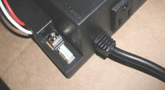
WARNING                                     AVERTISSEMENT
Do not use this appliance if any part has          Ne pas utiliser cet appareil s’il a été plongé,
been under water. Immediately call a               meme partiellement, dans l’eau. Appeler un
qualified service technician to inspect the        technician qualifié pour inspecter l’appareil et
appliance and to replace any part of the           remplacer toute partie du système de
control system and any gas control which           commande et toute commande qui a été
has been under water.                              plongée dans l’eau.
Toddlers, young children and others may be         Les tout-petits, les jeunes enfants et d'autres
susceptible to accidental contact burns. A         peuvent être sensibles aux brûlures par
physical barrier is recommended if there are       contact accidentel. Une barrière physique est
at risk individuals in the house. To restrict      recommandé s'il ya des personnes à risque
access to a fireplace or stove install an          dans la maison. Pour restreindre l'accès à une
adjustable safety gate to keep toddlers,           cheminée ou un poêle installer une barrière de
young children and at risk individuals out of      sécurité réglable pour garder les tout-petits,
the room and away from hot surfaces.               les jeunes enfants et les personnes à risque de
Any safety screen or guard removed for             la salle et à l'écart des surfaces chaudes.
servicing an appliance must be replaced            Tout écran ou grille de protection pour
prior to operating the appliance.                  l'entretien d'un appareil doit être remplacé
Installation and repair should be done by a        avant de faire fonctionner l'appareil.
qualified service person. The appliance            Installation et réparation doit être effectuée par
should be inspected before use and at least        un technicien qualifié. L'appareil doit être
annually by a professional service person.         inspecté avant son utilisation et au moins
More frequent cleaning may be required due         annuellement par un technicien qualifié. Un
to excessive lint from carpeting, bedding          nettoyage plus fréquent peut être nécessaire
material, et cetera. It is imperative that         en raison de peluches provenant des tapis,
control compartments, burners and                  literie, etc. Il est impératif que les
circulating air passageways of the appliance       compartiments de contrôle, les brûleurs et les
be kept clean.                                     conduits d'air de l'appareil soient gardés
                                                   propres.
This fireplace is a vented product. This           Ce foyer est un produit ventilé. Ce foyer doit
fireplace must be properly installed by a          être correctement installé par un technicien
qualified service person. The glass door           qualifié. La porte en verre doivent être placés
must be properly seated and sealed. If this        correctement et scellé. Si cet appareil n'est
unit is not properly installed by a qualified      pas correctement installé par un technicien
service person with the glass door properly        qualifié avec la porte en verre bien en place et
seated and sealed gas leakage can occur.           des fuites de gaz scellés peuvent se produire.
Caution: Label all wires prior to                  Attention : Au moment de l’entretien des
disconnection when servicing controls.             commandes, étiquetez tous les fils avant de
Wiring errors can cause improper and               les débrancher. Des erreurs de câblage
dangerous operation.                               peuvent entraîner un fonctionnement
                                                   inadéquate et dangereux.
Verify proper operation after servicing            S’assurer que l’appareil fonctionne
                                                   adéquatement une fois l’entretien terminé
If appliance is installed directly on carpeting,   Si l'appareil est installé directement sur un
vinyl tile or other combustible material other     tapis, carreaux de vinyle ou autre matériau
than wood flooring, the appliance shall be         combustible autre qu'un plancher de bois,
installed on a metal or wood panel extending       l'appareil doit être installé sur un panneau de
the full width and depth of the fireplace.         métal ou de bois se prolongeant sur toute la
                                                   largeur et la profondeur de la cheminée.
                                                                                      Page 5 of 53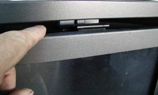
1.0 INTRODUCTION
1.1 SPECIFICATIONS

TABLE 1

                  ITEM               NATURAL GAS                   PROPANE
                                            (NG)                        (LP)
                INPUT: Hi           15,500 Btu/hr (4.54 kW)    14,500 BTU/hr (4.25 kW)
                INPUT: Lo           11,000 Btu/hr (3.22 kW)    11,500 BTU/hr (3.37 kW)
          MANIFOLD PRESSURE: Hi
             COLLECTEUR DE            3.5” w.c. (0.87 kPa)      10.0” w.c. (2.49 kPa)
             PRESSION: FORT
          MANIFOLD PRESSURE: Lo
             COLLECTEUR DE            1.7” w.c. (0.42 kPa)       6.4” w.c. (1.59 kPa)
            PRESSION: FAIBLE
            GAS INLET SUPPLY        Minimum: 5.0” w.c. (1.2    Minimum: 7.0” w.c. (1.74
               PRESSURE:                     kPa)                      kPa)
           ENTREE DE PRESSION       Maximum: 13.5” w.c. (3.4   Maximum: 13.5 w.c. (3.4
                                             kPa)                     kPa)

          ORIFICE SIZE: @ 0-4500’
                                           # 49 DMS                   # 57 DMS
            FORMAT D'ORIFICE:
               AIR SHUTTER               OPEN 1/8”min
                                                                    FULLY OPEN
              VOLET DE L’AIR              (3.175mm)
          CONTROL VALVE TYPE:          Skytech AF-40004          Skytech AF-40004
            TYPE DE SOUPAPE            Apex Control B081         Apex Control B081
                 VENTING
                                      2-ply aluminum vent        2-ply aluminum vent
               ÉVACUATION

THIS APPLIANCE IS ONLY FOR USE WITH THE TYPE OF GAS INDICATED ON THE RATING
                                    PLATE.
CET APPAREIL DOIT ÊTRE UTILISÉ UNIQUEMENT AVEC LE TYPE DE GAZ INDIQUÉ SUR LA
                            PLAQUE SIGNALÉTIQUE.

                                                                                        Page 6 of 53
APPLIANCE DIMENSIONS
                                                                             34.74”
                                                                    17.37”

                                                  10.28”

                                                                                                            32.38”
                                         27.92”
                                22.64”

                              1.00”
                 8.75”       0.50”
                                                                   34.20”

                                                                             39.19”

INSTALLATION CODES

This appliance is a Direct Vent appliance which draws all combustion air from outside the building through an intake vent pipe.
Installation must conform to local codes. In the absence of local codes, installation must conform to the National Fuel Gas
Code ANSI Z223.1/NFPA 54, or the current Natural Gas and Propane Installation Code CSA B149.1. The unit, when installed,
must be electrically grounded in accordance with local codes or, in the absence of local codes, with the National Electric Code
ANSI/NFPA No.70 or with the current Canadian Electrical Code CSA C22.1. In the state of Massachusetts, this product can
only be installed by a licensed plumber or a licensed gas fitter. Failure to comply will void the warranty.
This appliance has been certified for use with natural gas.
This appliance is not for use with solid fuels.

CODES D'INSTALLATION
Cet appareil est un appareil à évent direct, qui attire tous l'air de combustion provenant de l'extérieur du bâtiment par une
entrée d'évent.
L'installation doit se conformer aux codes locaux. En l'absence de codes locaux, l'installation doit être conforme au National
Fuel Gas Code ANSI Z223.1/NFPA 54, ou le gaz naturel actuel et le Code d'installation du propane CSA B149.1. L'unité, une
fois installé, doit être électriquement à la terre conformément aux codes locaux ou, en l'absence de codes locaux, avec le
National Electric Code ANSI / NFPA No.70 ou avec l'actuel Code canadien de l'électricité CSA C22.1
Cet appareil a été certifié pour une utilisation avec du gaz naturel.
Cet appareil n'est pas pour une utilisation avec des combustibles solides.
                                                                                                            Page 7 of 53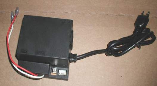
1.2 FEATURES
Ignition system:
     Standing pilot ignition system with thermopile and thermocouple flame detection and piezo igniter.

Gas control: * Optional*
   Gas control valve type:
      Automatic millivolt powered combination gas control valve with variable flame control for
      convenience and on/off switch. Optional digital remote on/off wall switch and/or optional wall
      thermostat (note: thermostats are not allowed in the United States). The gas valve does not
      require electricity from an external source.

Electronic Valve: * Optional *
    Automatic DC valve with AC power adapter. Hand held remote control.

                           Supreme Remote Control
                          Functional Operation Matrix

Initial Setup

Installation of (2) AAA-size batteries will activate the setup mode. Setup mode can
also be activated by pressing the FLAME REAR and PROG/TIME buttons
simultaneously for 5 seconds. The control will exit setup mode if no button is pressed
for 20 seconds. Appropriate icon on LCD will flash when ready for setup.
Press the UP or Down button in setup mode to change the temperature scale. Press
SET button to skip or advance to Fuel Type setup.
Press the UP or DOWN button to switch control from Natural to LP, or LP to Natural Gas. Press SET
button to skip or advance to Clock setup.
Press the UP or Down Button to set the hour. Press SET to advance to minutes.
Press the UP or Down button to set minutes. Press SET to advance to AM or PM.
Press the UP or Down button to set AM or PM. Press the SET button to advance to the day of week.
Use UP or Down button to select the day of the week.
The control will exit setup mode in 20 seconds.

MODE Button

The MODE button cycles the unit through the basic operational modes.
When off, press and release the MODE button to turn the unit on in Manual mode.
Press and release the MODE button again, and the unit will operate in the Thermostat mode.
Press and release the MODE button again, and the unit will turn off.
Program Mode

The Program function is controlled by the PROG/TIME button. The control may be programmed for up to
two settings for weekdays and two settings for weekends. The control is preset to factory settings.
When the Program Mode is activated, the unit will automatically be operating in the Thermostat Mode.
The unit will turn on or off based upon room and set temperature.
To activate the Program mode, press and release the PROG/TIME button.
To change the settings for the Program mode, press and hold the PROG/TIME button for 5 seconds. The
program feature will flash at the top of the screen.
Press the UP or DOWN button to change the setting of the weekday (MTWTF) P1 ON. Press and release
the SET button.
                                                                                       Page 8 of 53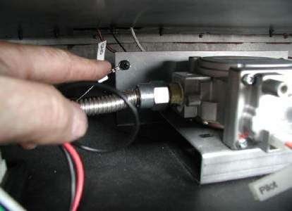
Press the UP or DOWN button to change the setting of P1 OFF. Press and release the SET button.
Press the UP or DOWN button to change the setting of P2 ON. Press and release the SET button.
Press the UP or DOWN button to change the setting of P2 OFF. Press and release the SET button.
Press the UP or DOWN button to change the setting of the weekend (SS) P1 ON. Press and release the
SET button.
Press the UP or DOWN button to change the setting of P1 OFF. Press and release the SET button.
Press the UP or DOWN button to change the setting of P2 ON. Press and release the SET button.
Press the UP or DOWN button to change the setting of P2 OFF. Press and release the SET button.
The Program Mode has been re-programmed.
Countdown Timer
The Countdown Timer Mode allows the control to operate the unit for up to 3 hours, in 10-minute
increments. It can be operated in either the Manual or Thermostat Modes.
To enter Timer Mode, press and release the TIMER button. The Timer icon will flash.
Press the UP or DOWN button to set the running time, in 10-minute increments. Press and release the
SET button. The timer will run for the set time duration.
Pressing the TIMER button while in Timer Mode will terminate the Timer operation. The Timer operation
will also terminate if the MODE button is cycled to off.
Thermostat Mode
The unit is placed in Thermostat Mode using the MODE button. Placing the unit in Thermostat Mode will
activate the numbers in the smaller window on the LCD screen.
Press the UP or DOWN button to change the thermostat set temperature. When the desired set
temperature appears, press and release the SET button to set.
If the SET button is not pressed, the set temperature will automatically be set after 5 seconds.
The Thermostat Mode can be de-activated by pressing the MODE button.
Thermostatic Flame Modulation
This control can perform Main Flame Modulation using the Thermostat. The control will shut the unit off
when the room temperature reaches 2 above set temperature. The Thermostat will automatically
modulate the main flame:
Manual Flame Modulation – Main Flame
To change the Flame Level manually, press the FLAME MAIN button. The current level will show in the
MAIN box on the LCD screen.
Press the UP or DOWN button to change the Flame Level.
When the unit is turned on, whether in Manual, Thermostatic, or Program Mode, the Main Flame will
automatically ignite at the High (7) setting. After 5 seconds, the flame will default to the previous setting.
Fan Control (Optional)
The unit must be ON to operate the Fan.
The Fan will turn on after 5 minutes of operation. Once the Fan comes on, it can be controlled using the
FAN button.
Press the FAN button, and the fan icon and speed will appear on the LCD screen.
Press the UP or DOWN button to control the fan speed (0-6). Press the DOWN button until 0 Level is
reached to turn the Fan off.
The fan will run for 12 minutes after the unit is shut off in any mode. The fan may not be controlled during
this period.
Page 9 of 53Continuous Pilot
The unit can be changed from Intermittent Pilot Ignition (IPI), to Continuous, or standing, pilot.
To place the unit in continuous pilot mode, press and release the PROG/TIME and the FLAME MAIN
buttons simultaneously. Continuous Pilot will appear on the LCD screen.
Repeat the simultaneous PROG/TIME and FLAME MAIN push to place the unit back in IPI mode.
This feature can also be activated by the Continuous Pilot (On/Off) switch on the Main Module.
Child Lock-Out
The Child Lock-out feature can be activated by pressing the PROG/Time and UP buttons simultaneously.
CP will appear on the LCD screen, and no signals can be sent from the transmitter.
To take the control out of Child Lock-out mode, repeat the above step. CP will disapper from the screen.
Learn Function
To program the system to a transmitter, press the LEARN button on the Main Module. A single audible
beep will be heard.
Press the MODE button on the transmitter to learn the transmitter to the system. A series of beeps will be
heard.
Up to two additional (NON-THERMOSTATIC) transmitters can be used simultaneously. To learn
additional transmitters, press and release the learn button again, and press the on button on the additional
transmitters.
To clear all transmitters and start over, press and hold the LEARN button for 10 seconds. A series of
three beeps will be heard, and the system is clear.
Low Battery Indicator
A low battery icon will appear on LCD screen when transmitter batteries reach low voltage level.
Thermal Safety
When the internal components of the Main Module reach 170F, the unit will automatically shut off, and
send a repetitive audible signal. The unit can be turned back on when the module cools below 160
Communication Safety
When in the Thermostat or Program Mode, the transmitter will send a silent signal to the module every 15
minutes. If a signal is not received within 2 hours due to dead batteries, lost transmitter, or transmitter out
of range, the unit will automatically shut down, and the module will send a repetitive audible signal.
1.3 INTENDED USE / USAGE PROPOSÉ
This appliance is intended to be used as a zero clearance fireplace. This unit is certified for installation in a bedroom or a
bed sitting room or a bathroom where the maximum input is within 50 cubic feet per 1000 Btu/hr, (i.e. 900 cubic feet for E
unit & 1600 cubic feet for H unit). In Canada all bedroom installations require the use of wall thermostats (note:
thermostats are not allowed in the United States).
Cet appareil est destiné à être utilisé comme un foyer à dégagement zéro. Cet appareil est certifié pour une installation
dans une chambre ou une chambre à coucher ou une salle de bain assis où l'entrée maximale est de moins de 50 pieds
cubes par 1000 Btu / h (i.e. 900 cubic feet for E unit & 1600 cubic feet for H unit). In Canada all bedroom installations
require the use of wall thermostats (note: thermostats are not allowed in the United States).
Page 10 of 531.4 GENERAL SAFETY / SÉCURITÉ GÉNÉRALE
Maintain adequate clearances around air openings into the combustion chamber.
Respecter les distances minimales convenables autour des bouches d'air dans la chambre de combustion.
Maintain adequate accessibility clearances for servicing and proper operation.
Respecter les distances minimales d'accessibilité suffisante pour l'entretien et bon.
This appliance shall not be connected to chimney flue serving a separate solid-fuel burning appliance.
Cet appareil ne doit pas être raccordé à une cheminée desservant un autre appareil brûlant des combustibles
solides.
The appliance area must be kept clear and free from combustible materials, gasoline and other flammable liquids
and vapors.
La zone appareil doit rester clair et exempt de matériaux combustibles, essence et autres vapeurs et liquides
inflammables.
The flow of combustion and ventilation air shall not be obstructed.
Le débit de combustion et de ventilation ne doit pas être obstrué.
The combustion air supply shall be in the same pressure zone as the drafthood relief opening on an appliance
equipped with a drafthood or as the vent outlet on an appliance not equipped with a drafthood.
L'alimentation en air de combustion doit être dans la zone même pression que l'ouverture de secours hotte à air
sur un appareil équipé d'une hotte à air ou que l'évent de sortie sur un appareil n'est pas équipé d'une hotte à air.
Do not use this appliance if any part has been under water. Immediately call a qualified service technician to
inspect the appliance and to replace any part of the control system and any gas control which has been under
water.
Ne pas se servir de cet appareil s’il a été plongé dans l’eau, même partiellement. Faire inspecter l’appareil par un
technicien qualifié et remplacer toute partie du système de contrôle et toute commande qui ont été plongées dans
l’eau.
Page 11 of 53IMPORTANT
PLEASE READ THE FOLLOWING CAREFULLY
It is normal for fireplaces fabricated of steel to give off some expansion and/or contraction noises
during the start up or cool down cycle.
It is not unusual for gas fireplaces to give off some odors the first time they are burned. This is
due to the oils and sealants in the manufacturing process.
PLEASE ENSURE YOU ROOM IS WELL VENTILATED DURING BURN OFF – OPEN ALL WINDOWS
It is recommended that you burn your fireplace for at least 4 (four) hours the first time you use it.
IMPORTANT
S'IL VOUS PLAÎT LIRE ATTENTIVEMENT CE QUI SUIT
Il est normal pour les foyers fabriqués d'acier à dégager une certaine expansion et / ou des bruits
de contraction pendant le démarrage ou cycle de refroidissement.
Il n'est pas inhabituel pour les foyers à gaz de dégager certaines odeurs la première fois qu'ils
sont brûlés. Cela est dû aux huiles et produits d'étanchéité dans le processus de fabrication.
S'IL VOUS PLAÎT VOUS ASSURER pièce est bien aérée pendant BRÛLER - Ouvrir toutes les
fenêtres
Il est recommandé que vous brûlez votre foyer pendant au moins 4 (quatre) heures la première
fois que vous l'utilisez.
WARNING
Hot while in operation. Do Not Touch. Severe burns may result. Keep children, clothing,
furniture, gasoline and other liquids having flammable vapors away.
Toddlers, young children and others may be susceptible to accidental contact burns. A
physical barrier is recommended if there are at risk individuals in the house. To restrict
access to a fireplace or stove install an adjustable safety gate to keep toddlers , young
children and at risk individuals out of the room and away from hot surfaces.
Any safety screen or guard removed for servicing an appliance must be replaced prior to
operating the appliance.
Installation and repair should be done by a qualified service person. The appliance should
be inspected before use and at least annually by a professional service person. More
frequent cleaning may be required due to excessive lint from carpeting, bedding material, et
cetera. It is imperative that control compartments, burners and circulating air passageways
of the appliance be kept clean.
AVERTISSEMENT
L’appareil est chaud lorsqu’il fonctionne. Ne pas toucher l’appareil. Risque de brûlures
graves. Surveiller les enfants. Garder les vêtements, les meubles, l’essence ou autres
liquides produisant des vapeur inflammables loin de l’appareil.
Les tout-petits, les jeunes enfants et d'autres peuvent être sensibles aux brûlures par
contact accidentel. Une barrière physique est recommandé s'il ya des personnes à risque
dans la maison. Pour restreindre l'accès à une cheminée ou un poêle installer une barrière
de sécurité réglable pour garder les tout-petits, les jeunes enfants et les personnes à risque
de la salle et à l'écart des surfaces chaudes.
Tout écran ou grille de protection pour l'entretien d'un appareil doit être remplacé avant de
faire fonctionner l'appareil.
Installation et réparation doit être effectuée par un technicien qualifié. L'appareil doit être
inspecté avant son utilisation et au moins annuellement par un technicien qualifié. Un
nettoyage plus fréquent peut être nécessaire en raison de peluches provenant des tapis,
literie, etc. Il est impératif que les compartiments de contrôle, les brûleurs et les conduits
d'air de l'appareil soient gardés propres.
Page 12 of 532.0 OPERATION
2.1 LIGHTING INSTRUCTIONS - for Intermittent Pilot
FOR YOUR SAFETY, READ BEFORE LIGHTING
WARNING: If you do not follow these instructions exactly, a fire or explosion may result causing property
damage, personal injury or loss of life.
A. This appliance is equipped with an ignition device which automatically lights the pilot. Do not try to light the pilot by hand.
B. BEFORE LIGHTING smell all around the appliance area for gas. Be sure to smell next to the floor because some gas is heavier than air and will
settle on the floor.
WHAT TO DO IF YOU SMELL GAS
Do not try to light any appliance.
Do not touch any electric switch; do not use any phone in your building.
Immediately call your gas supplier from a neighbour’s phone. Follow the gas supplier’s instructions.
If you cannot reach your gas supplier, call the fire department.
C. Use only your hand to push in or turn the gas control knob. Never use tools. If the knob will not push in or turn by hand, don’t try to repair it, call a
qualified service technician. Force or attempted repair may result in a fire or explosion.
D. Do not use this appliance if any part has been under water. Immediately call a qualified service technician to inspect the appliance and to replace
any part of the control system and any gas control which has been under water.
LIGHTING INSTRUCTIONS
1. STOP! Read the safety information above on this label.
2. Set the thermostat to the lowest setting.
3. Turn off all electric power to the appliance.
4. Do not attempt to light the pilot by hand.
5. Wait five (5) minutes to clear out any gas. Then smell for gas, including near the floor. If you smell gas, STOP! Follow “B” in the safety
information above on this label. If you don’t smell gas, go to the next step.
6. Turn on all electric power to the appliance.
7. Set thermostat to desired setting (or switch to "ON" if not using a thermostat).
8. If the appliance will not operate, follow the instructions "To Turn Off Gas To Appliance" and call your service technician or gas supplier.
TO TURN GAS OFF TO APPLIANCE
1.Set thermostat to lowest setting.
2.Turn on/off switch to off.
1. Pressure Taps
2. Main Valve Connection
3. Pilot Internal Solenoid Connection
4. Outlet Ports
5. Mounting Holes
7. Flow Control Screw
8. Pilot Connections
9. High/Low Connection
10. Inlet Ports
Page 13 of 532.1 INSTRUCTIONS D'ALLUMAGE - Pilote intermittent
POUR PLUS DE SÉCURITÉ, LIRE AVANT D’ALLUMER
AVERTISSEMENT: Quiconque ne respecte pas à la letter les instructions dans la présente notice risqué
de déclencher un incendie ou une explosion entraînant des dommages, des blessures ou la mort.
A. Cet appareil est équipé d'un dispositif d'allumage qui allume automatiquement le pilote. Ne pas tenter d'allumer le pilote à la main.
B. Avant d’allumer la veilleuse, reniflez tout autour de l’appareil pour déceleur une odeur de gaz. Reniflez près du plancher, car certains gaz sont
plus lourds que l’air et peuvent s’accumuler au niveau du sol.
QUE FAIRE SI VOUS SENTEZ UNE ODEUR DE GAZ:
Ne pas tenter d’allumer d’appareil.
Ne touchez à aucun interrupteur; ne pas vous server des telephones se trouvant dans le bâtiment.
Appelez immédiatement votre fournisseur de gaz depuis un voisin. Suivez les instructions du fournisseur.
Si vous ne pouvez rejoinder le fournisseur, appelez le service des incendies.
C. Ne pousser ou tourner la manette d’admission do gaz qu’à la main. Ne jamais employer d’outil à cette fin. Si la manette reste coincée, ne tentez
Pas de la réparer; appelez un technician qualifié. Quiconque tente de forcer la manette ou de la réparer peut provoquer une explosion ou un
incendie.
D. N’utilisez pas cet appareil s’il a été plunge dans l’eau, meme partiellement. Faites inspecter l’appareil par un technician qualifié et remplacez toute
partie du système de contrôle et toute commande qui ont été plongés dans l’eau.
INSTRUCTIONS D’ALLUMAGE
1. ARRÊTEZ! Lisez les instructions de sécurité sur la portion supérieure de cette etiquette.
2. Réglez le thermostat à la temperature la plus basse.
3. Coupez l’alimentation électrique de l’appareil.
4. Ne tentez pas d'allumer le pilote à la main.
5. Attendre cinq (5) minutes** pour laisser échapper tout le gaz. Reniflez tout autour de l’appareil, y compris près du plancher, pour déceler une
odeur de gaz, Si vous sentez une odeur de gaz, ARRÉTEZ! Passez à l’étape B des instructions de sécurité sur la portion supérieure (à gauche) de cette etiquette. S’il n’y a
pas d’odeur de gaz, passez à l’étape suivante.
7. Mettez l’appareil sous tension.
8. Réglez le thermostat à la temperàture désirée.
9. Si l'appareil ne fonctionne pas, suivez les instructions "Pour couper le gaz à l'appareil" et appelez votre technicien ou votre fournisseur de gaz
COMMENT COUPER L’ADMISSION DE GAZ
L’APPAREIL
1.Réglez le thermostat à la temperature la plus basse
2.Activer / OFF sur OFF.
1. Prises de pression
2. Raccordement de la vanne principale
3. Pilote de connexion interne solénoïde
4. Ports de sortie
5. Trous de montage
7. Vis de réglage du débit
8. Connexions pilote
9. High/Low Connection
10. Ports d'entrée
Page 14 of 532.1 LIGHTING INSTRUCTIONS – for Standing Pilot
FOR YOUR SAFETY, READ BEFORE LIGHTING
WARNING: If you do not follow these instructions exactly, a fire or explosion may result
causing property damage, personal injury or loss of life.
A. This appliance has a pilot which must be lighted by hand. When lighting the pilot, follow these instructions exactly.
B. BEFORE LIGHTING smell all around the appliance area for gas. Be sure to smell next to the floor because some gas is heavier than air and will
settle on the floor.
WHAT TO DO IF YOU SMELL GAS
Do not try to light any appliance.
Do not touch any electric switch; do not use any phone in your building.
Immediately call your gas supplier from a neighbour’s phone. Follow the gas supplier’s instructions.
If you cannot reach your gas supplier, call the fire department.
C. Use only your hand to push in or turn the gas control knob. Never use tools. If the knob will not push in or turn by hand, don’t try to repair it, call a
qualified service technician. Force or attempted repair may result in a fire or explosion.
D. Do not use this appliance if any part has been under water. Immediately call a qualified service technician to inspect the appliance and to replace
any part of the control system and any gas control which has been under water.
LIGHTING INSTRUCTIONS
1. STOP! Read the safety information above on this label.
2. Set the thermostat to the lowest setting.
3. Turn off all electric power to the appliance.
4. Controls are accessed by opening the bottom louver.
5. Push in gas control knob slightly and turn clockwise to “OFF”.
6. Wait five (5) minutes to clear out any gas. Then smell for gas, including near the floor. If you smell gas, STOP! Follow “B” in the safety
information above on this label. If you don’t smell gas, go to the next step.
7. Turn control knob counterclockwise pilot position.
8. Depress control knob and push in piezo igniter button. Once pilot ignites continue to hold the control knob in for one (1) minute after the pilot is lit.
Release knob and it will pop back up. Pilot should remain lit. If it goes out, repeat steps 4 – 7.
If knob does not pop up when released, stop and immediately call your service technician or gas supplier.
If the pilot will not stay lit after several attempts, turn the gas control knob to “OFF” and call your service technician or gas supplier.
9. Turn gas control knob counterclockwise to “ON”. Turn on all electric power to the appliance. Set thermostat to desired setting or turn appliance
switch to “ON” position then close bottom louver.
TO TURN GAS OFF TO APPLIANCE
1.Set thermostat to lowest setting.
2.Turn off all electric power to the appliance if service is to be performed.
3.Push in gas control knob slightly and turn clockwise to “OFF”, do not force.
Note: The valve is equipped with a safety lockout, once in the “OFF” position you must wait until the thermopile has cooled before attempting
to light the pilot (approximately 3 minutes).
Page 15 of 532.1 INSTRUCTIONS D'ALLUMAGE - pour veilleuse permanente
POUR VOTRE SÉCURITÉ, LIRE AVANT D'ALLUMER
ATTENTION: Si vous ne suivez pas exactement ces instructions, un incendie ou une
explosion entraînant des dommages matériels, des blessures ou des pertes de vie.
A. Cet appareil a un pilote qui doit être allumée à la main. Lorsque l'éclairage, le pilote, suivez ces instructions à la lettre.
B. AVANT L'ALLUMAGE odeur tout autour de l'appareil pour le gaz. Soyez sûr de sentir près du plancher, car certains gaz sont plus lourds que l'air
et se déposent sur le sol.
QUE FAIRE SI VOUS UNE ODEUR DE GAZ
Ne tentez pas d'allumer l'appareil.
Ne pas toucher à aucun interrupteur électrique; n'utilisez aucun téléphone dans votre édifice.
Appelez immédiatement votre fournisseur de gaz depuis un voisin. Suivez les instructions du fournisseur de gaz.
Si vous ne pouvez pas joindre votre fournisseur de gaz, appelez les pompiers.
C. Utilisez seulement votre main pour enfoncer ou tourner le bouton de contrôle du gaz. Ne jamais utiliser d'outils. Si le bouton ne sera pas enfoncer
ou tourner à la main, ne pas essayer de le réparer, appelez un technicien qualifié. Réparation de la force ou la tentative peut entraîner un incendie
ou une explosion.
D. Ne pas utiliser cet appareil si une partie a été sous l'eau. Appelez immédiatement un technicien qualifié pour inspecter l'appareil et remplacer toute
partie du système de contrôle et toute commande de gaz qui a été sous l'eau.
INSTRUCTIONS D'ALLUMAGE
1. STOP! Lire les consignes de sécurité ci-dessus sur cette étiquette.
2. Réglez le thermostat à réglage le plus bas.
3. Coupez l'alimentation électrique de l'appareil.
4. Les contrôles sont accessibles par l'ouverture de la persienne inférieure.
5. Poussez le bouton de contrôle du gaz et tourner vers la droite pour “OFF”.
6. Attendez cinq (5) minutes pour laisser échapper tout le gaz. Puis une odeur de gaz, y compris près du plancher. Si vous sentez une odeur de gaz,
ARRÊTEZ! Suivez «B» des consignes de sécurité ci-dessus sur cette étiquette. Si vous ne sentez pas de gaz, passez à l'étape suivante.
7. Tourner le bouton de commande antihoraire poste de pilote.
8. Enfoncez le bouton de commande et de pousser dans piézo allumeur bouton. Une fois pilote s'enflamme continuent à tenir le bouton de
commande pour un (1) minute après que le pilote est allumée. Relâchez le bouton et il apparaîtra sauvegarder. Veilleuse doit rester allumée. Si
elle s'éteint, répétez les étapes 4 - 7.
Si le bouton ne fait pas apparaître même, arrêtez et appelez immédiatement votre technicien ou votre fournisseur de gaz.
Si le pilote ne reste pas allumée après plusieurs tentatives, tournez le bouton de contrôle du gaz à "OFF" et appelez votre technicien ou votre
fournisseur de gaz.
9. Tourner le bouton de contrôle du gaz antihoraire sur "ON". Rétablissez l'alimentation électrique de l'appareil. Réglez le thermostat à la
température désirée ou tournez le commutateur appareil pour position "ON" persienne inférieure puis fermez.
À coupez le gaz À L'APPAREIL
1.Réglez le thermostat à réglage le plus bas.
2.Coupez l'alimentation électrique de l'appareil si le service doit être exécuté.
3.Poussez le bouton de contrôle du gaz et tourner dans le sens horaire sur "OFF", ne forcez pas.
Remarque: La vanne est équipée d'un verrouillage de sécurité, une fois dans la position "OFF" vous devez attendre que la thermopile a
refroidi avant de tenter d'allumer la veilleuse (environ 3 minutes).
Page 16 of 53Apex Control Valve
2.2 HEAT OUTPUT ADJUSTMENT
The valve supplied with the appliance has a HI/LO knob to control the heat output and flame height
(see valve diagram in Lighting Instructions, section 2.1).
3.0 INSTALLATION
3.1 INSTALLATION & SAFETY NOTES / NOTES D'INSTALLATION ET
DE SECURITE
Read all instructions before starting installation and follow them carefully during installation to ensure
maximum benefit and safety. Failure to follow these instructions will void your warranty and may
present a fire hazard. See the warranty at the back of this manual for disclaimers regarding improper
installation. This direct vent fireplace and it’s components are tested and safe when installed in
accordance with this installation manual.
Lisez toutes les instructions avant de commencer l'installation et de les suivre attentivement lors de
l'installation pour assurer un bénéfice et une sécurité maximales. Le non respect de ces instructions
annule la garantie et peut présenter un risque d'incendie. Voir la garantie à l'arrière de ce manuel
pour décharges de responsabilité concernant une mauvaise installation. Ce foyer à évacuation
directe et ses composantes sont testés et sûrs lorsqu'il est installé conformément aux instructions de
montage.
WARNING
Do not connect 120 VAC to the gas control valve or it’s components as this will
damage the valve.
Ne pas communiquer 120 VAC à la valve de contrôle du gaz ou de ses
composantes, car cela endommagerait la vanne.
Page 17 of 533.2 UNPACKING
Please check the appliance carefully for any damaged or missing components (specifically check the
glass condition). Report any problems to your dealer within 30 days of purchase.
3.3 INSTALLATION
For satisfactory results it is necessary to plan certain aspects of the installation prior to the
appliance’s final positioning. These include the vent system, the gas piping, and the fans wiring.
Combustible surfaces such as the hearth, mantle, and facing must also be planned for. Be sure to
leave adequate clearance for servicing and proper operation.
Pour des résultats satisfaisants, il est nécessaire de planifier certains aspects de l'installation avant le
positionnement final de l'appareil. Il s'agit notamment du système de ventilation, les canalisations de
gaz, et le câblage fans. surfaces combustibles tels que le foyer, le manteau, et en face doivent
également être prévues pour. N'oubliez pas de laisser un espace suffisant pour l'entretien et bon.
NOTE
ALL INSTALLATIONS REQUIRE VENTING.
Vented Gas Fireplace Not for Use with Solid Fuel
TOUTES LES INSTALLATIONS exigez l'aération.
Foyer au gaz à evacuation. Ne pas utiliser avec du combustible solide
SIDE VIEW OF TOP NON-COMBUSTIBLE BOARD
Heat baffle must be fixed
to non-combustible board
on installation.
45.00°
3.00”
4.00”
Page 18 of 533.3.1 INSTALLING NON-COMBUSTIBLE BOARD
WARNING
THE SURFACE ABOVE THE APPLIANCE GETS VERY HOT. IF PROPER FINISHING MATERIALS
ARE NOT USED, CRACKING CAN OCCUR.
LA SURFACE AU-DESSUS DE L'APPAREIL EST TRÈS CHAUDE. SI DES MATERIAUX DE
FINITION CORRESPONDANTS NE SONT PAS UTILISES, DES RISQUES PEUVENT
SURVENIR.
The 9.5” (241.3mm) above the appliance must not be finished with any combustible materials. If only a
painted surface is desired, a full single sheet of cement board should be used.
The manufacturer supplies only the minimum sized board required.
NOTE: To minimize joints, it may be best to replace the supplied non-combustible board with a larger piece.
SUPPLIED NON-COMBUSTIBLE
BOARD 9.5” (241.3mm) HIGH x 36”
(914.4mm) WIDE
Joint Compound where required:
Compounds such as Durabond 90 and tapes that are heat and cracking
resilient should be used when taping and mudding seams.
Setting tiles and grouting:
If using tiles we recommend you use tiles with a dry butt joint to be
installed using a two part mortar with an acrylic latex additive, to allow
for slight movement in the normal operation of the appliance. If grout is
used between the tiles we recommend a polymer-based grout.
Primer/Paint:
For a painted surface, use a 100% acrylic latex primer and finish coat.
NOTE: Light coloured surfaces may discolour due to heat.
TO CEILING
RECOMMENDED REPLACEMENT CEMENT BOARD IF
INSTALLING WITH PAINTED SURFACE ONLY. TOP OF FIREBOX
TO CEILING AND WIDTH OF WALL
TOP OF FIREBOX
Page 19 of 533.3.2 MINIMUM CLEARANCES / DÉGAGEMENTS
8.75”
0.75”
C
36.00”
NON-
COMBUSTIBLE
F
BOARD 9.5” X 36”
SUPPLIED BY
MANUFACTURER 36.00”
SEE 12.00”
MANUFACTURER Heat baffle must be
fixed to non-
NOTES
combustible board on
PREVIOUS PAGE installation. (see
A 40.00”
diagram on page 18.
40.00”
E 32.50”
26.59”
G
B 1.00” B 1.00”
D 6.00”
A = 40” TO INTERNAL CEILING
B = 1” TO INTERNAL SIDE COMBUSTIBLES (0” TO STANDOFFS)
C = 8.75” TO BACK WALL FROM FRONT OF UNIT (0” TO STANDOFFS)
D = 6” TO SIDE WALL
E = 32.5” FROM BOTTOM OF FIREPLACE TO COMBUSTIBLE MATERIAL
F=36” MINIMUM CEILING HEIGHT FROM TOP OF UNIT
G=40” MINIMUM FROM BOTTOM OF FIREPLACE TO MANTLE
(SEE DIAGRAM)
0” BASE OF UNIT TO FLOOR
0.75” REAR OF FIREPLACE TO BACK WALL
Clearances are in accordance with local installation codes and the requirements of the gas supplier.
**The mantel placement chart on this page illustrates the allowable mantel sizes and placements. The 45 degree angle can be
used to determine the allowable mantel size based on the elevation above the units upper trim.
Les dégagements sont en conformité avec les codes d'installation locaux et les exigences du fournisseur de gaz.
** Le tableau placement manteau sur cette page illustre les dimensions et les emplacements admissibles cheminée. L'angle de
45 degrés peut être utilisé pour déterminer la taille permise manteau repose sur l'élévation au-dessus de la garniture unités
supérieures.
Page 20 of 53When using paint or lacquer to finish the mantel, such paint or lacquer must be heat
ATTENTION
CAU TION
resistant ( up to 250o F ) to prevent discolorations.
Lors de l'utilisation de peinture ou de laque à la fin de la cheminée, de peinture ou
laque doit être résistante à la chaleur (jusqu'à 250o F) pour prévenir la décoloration.
3.3.3 GAS LINE INSTALLATION / INSTALLATION DE LA LIGNE de GAZ
Install supply line using any piping approved for your installation meeting CAN/CGA 6.10, AA 3, ANSI Z21.24 or Z21.45. A
qualified gas fitter should install the gas line in accordance with all local building codes. If codes permit, coiled copper
tubing may be used for gas supply.
Installez la ligne d'approvisionnement en utilisant toute la tuyauterie approuvé pour votre réunion d'installation CAN / CGA
6.10, AA 3, ANSI Z21.24 ou Z21.45. Un installateur de gaz qualifié doit installer la canalisation de gaz en conformité avec
les codes du bâtiment locaux. Si les codes le permettent, tube de cuivre enroulé peut être utilisé pour l'approvisionnement
en gaz.
Pressure taps are provided on the gas control for test gauge connections to measure the manifold and inlet pressures (see
Lighting Instructions).
Les sont fournis sur la commande de gaz pour les connexions prises de pression gabarit d'essai pour mesurer les
pressions multiples et d'une entrée (voir les Consignes d'allumage).
This appliance must be isolated from the gas supply piping system by closing its individual manual shut off valve during
any pressure testing of the gas supply piping system at test pressures equal to or less than 1/2 psi (3.45 kPa).
Cet appareil doit être isolé de l'alimentation en gaz en fermant son robinet arrêt pendant tout test de pression de la
canalisation de gaz à une pression égale ou inférieure à 1/2 psi (3.45 kPa).
The appliance and its appliance main gas valve must be disconnected from the gas supply piping system during any
pressure testing of that system at test pressures in excess of 1/2 psi (3.45 kPa).
L'appareil et son robinet d’arrêt doit être déconnectée de la canalisation de gaz pendant tout test de pression du système à des pressions
supérieures à 1/2 psi (3.45 kPa).
Install the gas line as follows:
The appliance shall be installed with a manual shut off ball valve and additional pressure regulator to bring line
pressure down to 14” w.c..
Installez la conduite de gaz comme suit:
L'appareil doit être installé avec une vanne manuelle à billes et régulateur de pression supplémentaire pour faire
pression ligne vers le bas à 14 "wc.
Upon initial firing check manifold pressure at pressure tap located on the front control
panel (see Lighting Instructions in section 2.1 ).
NOTE
Lors de la première vérification de la pression de tir collecteur à la pression du robinet
situé sur le panneau de commande avant (voir les Consignes d'allumage à la section 2.1).
WARNING
AVERTISSEMENT
DO NOT USE AN OPEN FLAME TO TEST FOR GAS LEAKS
NE PAS UTILISER UNE FLAMME DE TEST DE FUITES DE GAZ
Page 21 of 53Vous pouvez aussi lire