INSTALLATION GUIDE ILLUMISOFT ECO SERIES LED RETROFIT KITS: ALL MODELS - ILLUMISOFT LIGHTING
←
→
Transcription du contenu de la page
Si votre navigateur ne rend pas la page correctement, lisez s'il vous plaît le contenu de la page ci-dessous
Installation Guide
    Illumisoft Eco Series LED Retrofit Kits: All Models

          For Step By Step Installation Video:
          www.illumisoftlighting.com/install

USA and Canada 888-441-0555         ALL RIGHTS RESERVED BY ILLUMISOFT LIGHTING INC. 2017
                              ALL PRODUCTS COVERED UNDER 20+ US ISSUED AND PENDING PATENTS   1
  IllumisoftLighting.com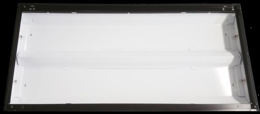
Illumisoft Eco Series LED Retrofit Kits: All Models
WARNING
FAILURE TO FOLLOW THESE INSTRUCTIONS AND WARNINGS MAY RESULT IN SERIOUS INJURY OR SIGNIFICANT PROPERTY DAMAGE.
For your protection, carefully read these warnings and instructions in their entirety before installing or maintaining this equipment. These
instructions do not attempt to cover all installation and maintenance situations. If you do not understand these instructions or if additional
information is required, contact your Illumisoft Lighting representative. Retain these instructions for maintenance reference.

AVERTISSEMENT
LE NON-RESPECT DE CES INSTRUCTIONS ET AVERTISSEMENTS PEUT ENTRAÎNER DES BLESSURES GRAVES OU D'IMPORTANTS DÉGÂTS MATÉRIELS.
Pour votre protection, lisez soigneusement et entièrement ces instructions et avertissements avant l'installation ou l'entretien de cet équipement.
Ces instructions ne couvrent pas tous les cas rencontrés au cours de l'installation ou de l'entretien. Si vous ne les comprenez pas ou si vous avez
besoin d'un complément d'information, veuillez contacter votre représentant Illumisoft Lighting local. Conservez ces instructions à titre de référence
pour l'entretien.

WARNING
RISK OF FIRE OR ELECTRIC SHOCK
The Eco Series must be installed and maintained by a professional electrician in accordance with the applicable federal, state and local laws,
regulations and electrical codes, and the installation instructions provided in this document. This professional should be familiar with the
construction and operation of this product and any hazards involved. If not qualified, do not attempt installation. Contact a qualified electrician.

AVERTISSEMENT
RISQUES D'INCENDIE OU DE DÉCHARGE ÉLECTRIQUE L'Eco Series doit être installé et entretenu par un électricien professionnel conformément aux
lois fédérales, étatiques et locales, aux réglementations et codes électriques applicables et aux consignes d'installation mentionnées dans ce
document. Ce professionnel devra bien connaître la construction et le fonctionnement de ce produit, ainsi que tous les risques encourus. Si aucune
personne n'est qualifiée, ne tentez pas l'installation. Prenez contact avec un électricien qualifié.

WARNING
RISK OF PERSONAL INJURY

This equipment may have sharp edges. Wear gloves to prevent cuts or abrasions when removing from carton, handling and maintaining this
equipment.

AVERTISSEMENT
RISQUES DE DOMMAGES CORPORELS

Cet équipement peut présenter des arêtes vives. Portez des gants pour éviter les coupures ou les écorchures lorsque vous le sortez du carton, le
manipulez et l'entretenez.

WARNING                                     WARNING
RISK OF FIRE, ELECTRIC SHOCK OR             RISK OF FIRE OR ELECTRIC SHOCK: To prevent wiring damage or abrasion, do not expose wiring to edges of
PERSONAL INJURY                             sheet metal or other sharp objects.

Do not install in a damaged fixture.        AVERTISSEMENT
                                            RISQUES D'INCENDIE OU DE DÉCHARGE ÉLECTRIQUE: N'exposez pas le câble aux bords d'une feuille
Before installation, turn power off.        métallique ou à d'autres objets pointus pour éviter de l'endommager ou de l'abraser.

AVERTISSEMENT                               Caution
RISQUES D'INCENDIE, DE DÉCHARGE             This kit is designed for permanent installation in ordinary (Non Hazardous) locations in accordance with
ÉLECTRIQUE OU DE DOMMAGES                   the National Electrical Code and all applicable local codes. Do not use in areas of limited ventilation or in
CORPORELS                                   high ambient enclosures.

N'installez pas sur un luminaire            Mise en garde
endommagé.                                  Ce kit a été conçu pour une installation permanente dans un lieu ordinaire (non dangereux)
Coupez l'alimentation avant                 conformément au code électrique national et à tous les codes locaux applicables. Ne l'utilisez pas dans des
l'installation.                             zones à aération limitée ou dans des enceintes à températures élevées.

Caution
This kit is designed for permanent installation in ordinary (Non Hazardous) locations in accordance with the National Electrical Code and all
applicable local codes. Do not use in areas of limited ventilation or in high ambient enclosures.

Mise en garde
Ce kit a été conçu pour une installation permanente dans un lieu ordinaire (non dangereux) conformément au code électrique national et à tous les
codes locaux applicables. Ne l'utilisez pas dans des zones à aération limitée ou dans des enceintes à températures élevées.

                                                                                                                                                        2
Illumisoft Eco Series LED Retrofit Kits: All Models

Notice
Do not use abrasive materials, glass cleaners or other solvents on the lens. To clean the lens, use a mild soap solution. Do not expose the product to
substances and /or materials containing sulphur, chlorine or other halogen compounds and to chemicals mentioned in below table.
Category           Chemical Name
Solvents           Toluene, xylene, benzene, chloromethane, chloroform, ethyl
                   acetate, butyl acetate, acetone, MEK, MIBK
Acid               HCl, H2SO4, HNO3
Alkali             KOH, NaOH, LiOH, Ca(OH)2
Oil                Diesel oil, petroleum, hydro carbons

Attention
N'utilisez pas de matériaux abrasifs, de nettoyants pour vitres ou d'autres solvants sur la plaque de recouvrement ou les lentilles. Nettoyez la plaque
avec une solution contenant un savon doux. N'exposez pas le produit aux substances et/ou matières contenant du soufre, du chlore ou d'autres
composés halogènes et aux produits chimiques mentionnés dans le tableau ci-après.
Catégorie           Nom chimique
Solvants            Toluène, xylène, benzène, chlorométhane, chloroforme, acétate d'éthyle, acétate de butyle, acétone, butanone, hexone
Acide               HCl, H2 SO4 , HNO3
Alcali              KOH, NaOH, LiOH, Ca(OH)2
Pétrole             Gazole, pétrole, hydrocarbures

Notice
Handle components with care. Do not drop, slide or scratch any of the components to prevent visual damage to the product, loss of functionality or
difficulties during installation.

Attention
Manipulez avec soin les composants. Ne laissez ni tomber, ni glisser et ne griffez pas les composants pour éviter les dommages visuels infligés au
produit, une perte de fonctionnalité ou des difficultés d'installation.

Notice
The original certification mark and nameplate must remain intact and visible after any labels from this retrofit kit are applied.

Attention
La marque de certification originale et la plaque signalétique doivent rester intactes et visibles après l'étiquette de Ce kit de rénovation est appliqué.

DO NOT MAKE OR ALTER ANY OPEN HOLES IN AN ENCLOSURE OF WIRING OR ELECTRICAL COMPONENTS DURING KIT INSTALLATION.

IL EST INTERDIT DE FAIRE OU DE MODIFIER UNE OUVERTURE DANS UN BOÎTIER DE CÂBLAGE OU DE COMPOSANTS ÉLECTRIQUES AU COURS DE
L’INSTALLATION DU NÉCESSAIRE.

THIS RETROFIT KIT IS ACCEPTED AS A COMPONENT OF A LUMINAIRE WHERE THE SUITABILITY OF THE COMBINATION SHALL BE DETERMINED BY
AUTHORITIES HAVING JURISDICTION.

LE NÉCESSAIRE DE MODERNISATION EST ACCEPTÉ À TITRE DE COMPOSANT D’UN LUMINAIRE LORSQUE LA PERTINENCE DE LA COMBINAISON DOIT
ËTRE DÉTERMINÉE PAR PAR LES AUTORITÉS COMPÉTENTES

WARNING – RISK OF FIRE OR ELECTRIC SHOCK. INSTALLATION OF THIS
RETROFIT ASSEMBLY REQUIRES A PERSON FAMILIAR WITH THE CONSTRUCTION AND OPERATION OF THE LUMINAIRE’S ELECTRICAL SYSTEM AND THE
HAZARD INVOLVED. IF NOT QUALIFIED, DO NOT ATTEMPT INSTALLATION. CONTACT A QUALIFIED PERSON.

AVERTISSEMENT – RISQUE D’INCENDIE OU DE CHOC ÉLECTRIQUE. L’INSTALLATION DE CE NÉCESSAIRE DE MODERNISATION EXIGE UNE
PERSONNE FAMILIÈRE AVEC LA CONSTRUCTION ET LE FONCTIONNEMENT DU
SYSTÈME ÉLECTRIQUE DU LUMINAIRE ET DES RISQUES ASSOCIÉS. TOUTE PERSONNE QUI N’EST PAS QUALIFIÉE NE DOIT FAIRE AUCUNE TENTATIVE
D’INSTALLATION ET DOIT CONTACTER UNE PERSONNE QUALIFIÉE.

                                                                                                                                                             3
Illumisoft Eco Series LED Retrofit Kits: All Models
Typical Compatible Host Troffer
A
Ballast/Wire Cover
A: 47.875” to 23.75”
B B: 9” to 23.75”
Lampholder Assemblies
Mounting Flanges
Typical Compatible Host Troffer – Ballast Cover Removed
Ballast Wires to
AC Disconnect
Lampholders
Ballast
Branch Circuit
Supply Wires:
Ballast Wires to White = Neutral
Lampholders Black = Hot
Host Lighting Fixture
The Illumisoft Lighting Eco Series is designed for installation in a wide variety of indoor fluorescent based fixtures in
horizontal applications.
• The Illumisoft Lighting Eco Series are non air-handling.
• Install the Illumisoft Lighting Eco Series only in fluorescent based host lighting fixtures.
• For LED Driver Connection Option #1, the Eco Series requires a minimum clearance of 3”between the ballast cover
and the fixture outer aperture.
• For LED Driver Connection Option #2, the Eco Series requires a minimum host troffer depth of 3.25”
• The Eco Series may be ordered for use with host troffers with dimensions as shown above, used in standard 15/16”
NEMA G and NEMA NFG t-grids, 20” x 60” , 36” x 36” and metric ceiling grids.
• Due to the wide variety in troffers and ceiling grids, it is recommended that the installer does a test install before
commencing a renovation.
• Please verify voltage that the Illumisoft Lighting Eco Series product label matches the mains voltage.
• Installation of the Eco Series requires that the host lighting fixture be moved vertically in the ceiling grid a sufficient
amount to allow the insertion of the Eco Series mounting trim between the host fixture’s mounting flanges and the
T-bar grids. If the host fixture is attached to the T-bars with seismic clips, screws or other retention brackets and is
immobile, then the seismic clips, screws or other retention brackets must be loosened sufficiently to install the Eco
Series mounting trim. Be sure to re-secure the seismic clips, screws or other retention brackets after installation of
the Eco Series.
The LED retrofit kit is for installation in currently installed recessed, Non - IC (non-insulated ceiling) certified luminaires that has the
construction features and dimensions similar to that shown in the photographs and/or drawings and where it has a suitable electrical
enclosure for supply connections per UL1598/CSA 250 Standard.
4Illumisoft Eco Series LED Retrofit Kits: All Models
Note: The installation procedures including all of its warning, cautions and other literature including the illustrations of the
intended host troffer for installation of the retrofit kits, are contained in these instructions unless otherwise specifically indicated.
The Eco Series retrofit model depicted in these instructions is a representative fixture for illustrative purposes only.
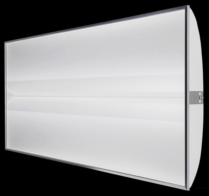
WHAT’S INCLUDED IN THIS RETROFIT KIT:
LED INPUT WIRES
OPTICAL
FILM 98% EFFICIENT
LENS REFLECTION FILM 98% EFFICIENT
END PANELS REFLECTION FILM
REFLECTOR
ALUMINUM
FRAME HEAT SINK
1. ECO SERIES FIXTURE
1.625”
23.875” TO 60”” 11.75” TO 23.75”
2. TWO SIDE MOUNTING STRIPS 3. TWO END FILLER STRIPS
DRIVER OUTPUT CONNECTORS DRIVER OUTPUT CONNECTORS
DIMMER CONNECTOR (OPTIONAL) DIMMER CONNECTOR
LED Driver
AC Disconnect
4A. LED DRIVER & WIRING ASSEMBLY 4B. LED DRIVER & WIRING
(WHEN ORDERED WITH DRIVER OPTION #2) (WHEN ORDERED WITH DRIVER OPTION #1)
5. 2 X 1/4” #8 SELF-DRILLING SCREWS
(DRIVER OPTION #1 ONLY)
1 X 1.5” #10 SELF-DRILLING SCREW
(DRIVER OPTION #2 ONLY)
6. TROFFER LABEL
TOOLS NEEDED: WIRE CUTTER/STRIPPER, MEDIUM PHILIPS OR ROBERTSON
SCREWDRIVER, ELECTRIC SCREWDRIVER WITH 5/16” SOCKET BIT 5Illumisoft Eco Series LED Retrofit Kits: All Models
LED DRIVER CONNECTION OPTION #1: LED DRIVER MOUNTS INSIDE THE HOST TROFFER’S BALLAST COVER
IF THE HOST TROFFER HAS A MINIMUM OF 3” OF DEPTH CLEARANCE BETWEEN THE BALLAST COVER AND THE HOST
FIXTURE’S MOUNTING FLANGES, THEN FOLLOW THE INSTRUCTIONS BELOW. IF THERE IS INSUFFICIENT CLEARANCE, THEN
PROCEED TO LED DRIVER CONNECTION OPTION #2
WARNING RISK OF FIRE, ELECTRIC SHOCK OR PERSONAL INJURY
BEFORE INSTALLATION, TURN THE POWER OFF!
2. Remove louver or door with lens and discard or
1. Turn the power off! even better, recycle!
3. All internal parts of the host troffer may be left in
place except for the ballast cover which needs to be
Remove Ballast Cover temporarily removed to access the host troffer
wiring. Some troffers may require 1 lamp to be
temporarily removed in order to remove the ballast
cover. However, if required by law or code,
remove and properly dispose of the lamps and
ballast. Regardless, we highly recommend they be
removed and safely discarded!
Photo #1 Photo #2 BRANCH Photo #3
SUPPLY
WIRES
Cut Ballast Old
Output Ballast
Wires Wires
AC Disconnect
AC Disconnect
4. Unplug the disconnect from the ballast input (if equipped as shown on photos #1 and #3). If not (photo #2 above),
cut the ballast AC input wires as close to the ballast as practicable. Strip about 1/2” of insulation of both wire ends.
Detach the ballast from the host troffer. Leave the lamp holders installed.
#8 Self Drilling Hex Screws
5. Attach the LED driver to the host troffer with the
two supplied self-drilling 1/4” #8 hex screws. You
can reuse one or both of the previous ballast screw
holes.
LED Driver
6Illumisoft Eco Series LED Retrofit Kits: All Models
Driver AC Branch Supply
Disconnect AC Disconnect
Old Ballast LED Driver
Wires AC Disconnect
6a). If so equipped as previously described, connect 6b). If there is no AC disconnect as previously
the LED driver AC disconnect to the branch supply AC described, insert the old ballast wires into the LED
disconnect. driver disconnect, making sure to observe the polarity!
7. Hang the Eco fixture from the ceiling T-bar nearest the LED driver output wires using the supplied hook.
Opening
LED Strip Connectors
8. Place the supplied label in a prominent place 9. Re-install the host troffer’s ballast cover while
inside the host troffer. Do not cover the existing routing the LED Wire Extension out an existing
troffer information label. opening as shown.
10. Connect the LED input wires fro the Eco
Fixture to the LED driver output connectors. Be
sure to match the red wires (or wires labeled red)
LED INPUT from the Eco fixture with the red wires from the
WIRES FROM driver. In the case of black and white LED wires,
ECO FIXTURE connect the black wire to the black wire on the
driver output connector.
DRIVER OUTPUT
CONNECTORS
7Illumisoft Eco Series LED Retrofit Kits: All Models
LED DRIVER CONNECTION OPTION #2: USE THE SUPPLIED WIRING ENCLOSURE
For all other installations other than LED Driver Connection Option #1, use the following instructions.
WARNING RISK OF FIRE, ELECTRIC SHOCK OR PERSONAL INJURY
BEFORE INSTALLATION, TURN THE POWER OFF!
2. Remove louver or door with lens and discard or
1. Turn the power off! even better, recycle!
Ballast Cover
3. Remove and safely dispose of the
ballast cover and all lamps.
Lamps
Photo #1 Photo #2 BRANCH Photo #3
SUPPLY
WIRES
Cut Ballast Old
Output Wires Ballast
Wires
AC Disconnect AC Disconnect
4. Unplug the disconnect from the ballast input (if so equipped as shown on the left and far right photo). If not, cut
the ballast AC input wires as close to the ballast as practicable. Strip about 1/2” of insulation of both wire ends
(middle photo above). Detach the ballast from the host troffer and safely dispose of it. Leave the lamp holders
installed.
8Illumisoft Eco Series LED Retrofit Kits: All Models
Driver and Wiring Enclosure
Driver AC
Driver AC
Disconnect Old Ballast Wires
Old Ballast Wires Disconnect
5. Prepare to insert the old ballast wires into the 6. Insert the old ballast wires into the LED driver
LED driver disconnect. Hold the AC wires from the disconnect, making sure to observe the polarity! If
driver enclosure with one hand, letting the equipped with an AC disconnect as previously
enclosure hang. described, mate the connectors.
Deeper Side of Enclosure
Troffer Side Panel
7. Lay the enclosure over the wiring as shown, and 8. Using the supplied #10 self-drilling hex screw,
align the enclosure as shown. Make sure all wires scratch a mark on the host troffer to mark a spot. Let
are safely inside the enclosure. the driver enclosure hang. Drill the self drilling screw
on the mark, leaving about 1” of the screw sticking out.
Screw Head
Keyhole Slot Driver and Wiring
Enclosure
PLACE THIS END OF THE
ENCLOSURE OVER THE WIRING
9. Place the driver enclosure so the screw head 10. In an application where the branch circuit wiring
protrudes through the keyhole slot as shown. Make to the troffer enters the side of the troffer and it
sure all the wires are securely inside the enclosure, cannot be moved to the back of the troffer, use the
then tighten the screw securely. optional wiring enclosure as shown. Follow the same
basic steps as #1-11, making sure to place the end of
the wiring enclosure securely over the wiring as
11. Place the supplied label in a
shown above, with no gaps, and no pinched wires.
prominent place inside the host troffer. 9Illumisoft Eco Series LED Retrofit Kits: All Models
Installation of the Eco Fixture Into the Host Troffer
Connect the LED input wires of the Eco Series to the LED driver output connector.
NOTE: Make sure to mount the end of the Eco fixture with the wires closest to the end of
the driver enclosure with the output connector. Arrange the cable to the side of the fixture
so that it does not sit on top of the Eco Fixture when installed. This will help ensure that the
wires or connectors do not get pressed against the reflectors after installation, which can
cause shadowing.
SIDE MOUNT STRIP FLANGE
TROFFER FLANGES
SIDE MOUNTING STRIP. SIDE MOUNT STRIP
INSERT BETWEEN T-BAR
CEILING T-BAR FLANGE
AND TROFFER FLANGE
1. Push up on one side of the host troffer (one of the sides with the latch holes) about ¼” and insert a Side Mounting
Strip between the T-bar flange and the Troffer Flange. The Flange of the Side Mounting Strip must nest outside of the
Troffer Flange as shown. It may help to angle the Side Mounting Strip while inserting.Illumisoft Eco Series LED Retrofit Kits: All Models
2. Repeat Step #13 for the opposing
side of the host troffer.
Installed Side Mounting Strips
Side Mounting Strip
Eco Series
Frame
Eco Series
Frame
Frame Nesting Ridge
3. Insert the Eco Series into the host troffer so that the two opposing outer frame members of the Eco Series nest on
the Frame Nesting Ridge on the Side Mounting Strips. The opposing sides of the Eco Series Frame nests on the Frame
Nesting Ridge as shown in the above cut-away view.
NOTE: Make sure to mount the end of the Eco fixture with the wires closest to the end of the driver enclosure
with the output connector. This will help ensure that the wires or connectors do not get pressed against the
reflectors after installation, which can cause shadowing.
Eco Series Filler Strips
Side Mounting Strips
Center Fixture
Between Cross-Tees
4. Center the Eco Series in the host troffer as necessary by sliding it along the Side Mounting Strips.
Insert both opposing Filler Strips between the remaining opposing host troffer flanges and the T-bar flanges as
shown above.
Cleaning
To clean bugs, dust or debris from the inside of
the Eco Series after installation, remove both End
Filler Strips. Remove the Eco Series from the host
troffer and hold it vertical. The flexible end
panels can be gently pulled back to allow the
debris to fall out. Re-install the Eco Series into
the host troffer as previously described.
5. Enjoy your Eco Series LED Retrofit for many years to come!
11Illumisoft Eco Series LED Retrofit Kits: All Models
Emergency Battery Backup Option
IMPORTANT SAFEGUARDS
When using electrical equipment, basic safety precautions should always be followed including:
READ AND FOLLOW ALL SAFETY INSTRUCTIONS
WARNING: Risk of fre or electric shock. Luminaire wiring and electrical parts may be damaged when drilling for
installation of LED Emergency Backup. Check for enclosed wiring and components.
WARNING: Risk of fire or electric shock. This LED Emergency Backup installation requires knowledge of
luminaires electrical systems. If not qualifed, do not attempt installation. Contact a qualifed electrician.
WARNING: Risk of fre or electric shock LED Emergency Backup is only for use in surface mount or recessed Type
IC or Non-IC luminaires listed to UL Standards. Suitable for use in damp locations and plenum spaces. Not for use
in heated air outlets or hazardous locations.
WARNING: To prevent wiring damage or abrasion, do not expose wiring to edges of sheet metal or other sharp
objects.
WARNING: Do not make or alter any open holes of the wiring enclosure or electrical component enclosure
during installation. Only those open holes indicated in the instructions and/or drawings may be added or altered
as a result of LED Emergency Backup installation. Do not leave any other open holes in the wiring enclosure or
electrical component enclosure during installation.
CAUTION: Before installing, make certain the AC power to the fxture is off.
CAUTION: The electrical rating of this product is 120-277V. Installer must confrm that there is 120- 277V at the
fxture before installation.
CAUTION: LEDs are extremely bright. Do not look directly at the LED light source for extended time as over-
exposure may cause harm to the eyes.
Do not use outdoors.
Use caution when servicing batteries. Battery acid can cause burns to skin and eyes. If acid is spilled on skin or in
eyes, fush acid with fresh water and contact a physician immediately.
Equipment should be mounted in locations and at heights where it will not readily be subjected to tampering by
unauthorized personnel.The use of accessory equipment not recommended by the manufacturer may cause an
unsafe condition.
Do not use this equipment for other than intended use.
This emergency pack has been evaluated to and found compliant to UL 924. The emergency pack assembly is
accepted as a component of a luminaire where the suitability of the combination shall be determined by UL or
Authorities Having Jurisdiction. The as-installed performance of the system must meet or exceed all Federal,
State, and Local code requirements.Illumisoft Eco Series LED Retrofit Kits: All Models
Emergency Battery Backup Option
What’s included:
1. Battery pack with wire connector.
2. Two #8 self drilling screws
Installation Intructions
Read and understand all warning and notes stated above before proceeding with installation.
1. Connect the battery to the driver enclosure using the
mating connector as shown.
BATTERY PACK
ATTACH SCREWS HERE 2. Attach the battery along the opposite troffer edge as
the wiring enclosure as shown, using the two supplied
self drilling #8 screws.
3. Apply the supplied luminaire modification label.
Eco Series Retrofit Kits have rated efficacies ranging from 136 to 167 lumens/watt. The actual lumen output of any
given Eco Series fixture will be approximately 5 times (5 watt option) and 12 times (12 watt option) the stated
efficacy your particular model. For example, if the Eco Series fixture is rated at 152 lumens/watt, the the lumen
output power failure conditions will be approximately 12 X 152=1824 lumens for a minimum of 90 minutes (12 watt
option).
Determining Adequacy of Means-of-Egress Lighting Levels
Follow industry standards by utilizing available .ies fles and lighting design software for your dedicated emergency
luminaires, with the above calculated emergency lumens, and validate your as-installed plans in accordance with the
applicable life safety codes governing your project. While these products are compliant with the requirements of UL
Standard 924, it is ultimately the responsibility of the designer/specifer to assure the as-installed system delivers
code compliant path of egress illumination in accordance with federal, state or local municipal
requirements.Illumisoft Eco Series LED Retrofit Kits: All Models
Master/Satellite Option Installation Instructions
EXISTING TROFFERS ARE SOMETIMES WIRED IN
A MASTER/SATELLITE CONFIGUATION AS
SHOWN.
EXISTING HOST TROFFERS WIRING OVERVIEW
The satellite fixture orginally may have been
An existing red and
Branch circuit wiring connects as
blue ballast wire routed wired with many possible configurations of
normal to the master troffer ballast wire numbers and colors that are routed
to satellite troffer
from the master to satellite troffer. Typically
these will include at least one red wire and one
blue wire. However there may be several of
each, making it difficult to know which wires in
the master correspond to which wire in the
satellite.
We recommend removing all unused ballast
wires so that only a red and blue wire remain.
MASTER TROFFER SATELLITE TROFFER
LED wires to the
Eco Fixture
installed into the LED wires attached to the Eco Fixture
satellite troffer. installed into the satellite troffer.
LED wires to the Eco Fixture installed
into the master troffer.
Insert the existing
blue ballast wire into the
black side of the disconnect.
Insert the existing blue Insert the existing
ballast wire into the black red ballast wire into the
side of the disconnect. white side of the disconnect. Insert the existing red
ballast wire into the white
Insert the blue and red wires as identified into the side of the disconnect.
push-in disconnect as shown.Vous pouvez aussi lire