INSTRUCTION MANUAL MANUEL D INSTRUCTIONS - ATGAMES
←
→
Transcription du contenu de la page
Si votre navigateur ne rend pas la page correctement, lisez s'il vous plaît le contenu de la page ci-dessous
INSTRUCTION Manual
                 MANUEL D'INSTRUCTIONS
                                              MODEL: HA8810

                                                                            Sign Up at www.arcadenet.net
                                                                            Inscrivez-vous sur www.arcadenet.net

Sign Up For ArcadeNet® !                            Inscrivez-vous à l’ArcadeNet !
 More Games to Play                                    Encore plus de jeux avec Instant Play
 Discounts and Special Offers for Members              Du jeu en ligne avec des tableaux des scores
 Online Multiplayer and Voice Chat                     Des offres spéciales pour nos membres, et bien plus
 Global Leaderboards and Leagues Events                encore…

                                            www.atgames.net
Index Assembly Guide/Guide d'assemblage P2 LEGENDS ULTIMATE MINI Features/ P 15 Fonctionnalités LEGENDS ULTIMATE MINI Quick Start Guide/ GUIDE DE DÉMARRAGE RAPIDE P 16 How to Update Firmware/ P 17 Comment mettre à jour le MICROPROGRAMME How to sign in with your ArcadeNet® account/ P 17 Comment vous connecter à votre compte ArcadeNet® HOW TO CONNECT ATGAMES BLAST! DONGLES AND P 18 CONSOLES TO LEGENDS ULTIMATE MINI/ COMMENT CONNECTER LES DONGLES ET LES CONSOLES ATGAMES BLAST! ET LES CONSOLES À LA LEGENDS ULTIMATE MINI When to safely power off arcade/ P 19 Quand mettre hors tension en toute sécurité LA BORNE WARRANTY INFO/ Informations sur la garantie P 19 Featured Games/ Jeux Inclus P 20 Safety Notice, FCC Statement/ P 21 Conditions D'utilisation, Déclaration FCC, AVIS de sécurité ISED Statement/ Déclaration de l'ISED P 23
Assembly Guide/ Guide d’assemblage

• Tools Needed
  (NOT INCLUDED)
• OUTILS NECESSAIRE
  (non inclus)

                   Phillips head screwdriver       Straight head screwdriver
                    Tournevis cruciforme             Tournevis à tête plate
Parts/ Pièces

                                                                           B
            A
                                                   C
                                   F
                                                       C

                                                                 H

                                                   I

                                       D

                                               E                         G

        J                                          D

                     O                                 P   X2

                                                   Pinball kit
Assembly Guide/ GUIDE D’ASSEMBLAGE
Screws/ Vis
S1 X16 S2 X16 S3 X3
S4 X2 S5 X10 S6 X4 S9 X4
CORD/ CORDON
Power adapter
K Alimentation
Anti-Tipping Kit/ SYSTEME ANTI BASCULE
L X2 M X2 S7 X2 S8 X2
Cable tie
N Serre-Câble
ACCESSORIES/ accessoires
Q Suction cup
VentouseASSEMBLY STEPS/ GUIDE D’ASSEMBLAGE
• HOW TO USE THE CAM BOLT KIT/ Comment utiliser le boulon à came
Step A Phillips head Step B Step C Step D
screwdriver
Straight head
screwdriver
Cam Bolt
Cam Lock
Cam Bolt Arrow
Cam Bolt Cam Lock
Step A. Use Phillips head screwdriver to fasten the cam bolt onto the panel. To avoid insufficient length to
connect the cam lock, please do not overtighten it.
Step B. When attaching two panels, please make sure the cam bolts align with the holes.
Step C. Insert the cam locks to the matching holes.
Step D. Tighten clockwise with straight head screwdriver.
Etape A. utilisez le tournevis cruciforme pour attacher le boulon à came au panneau. Pour éviter d’avoir une
longueur insuffisante lorsque vous connecterez le verrou à came, ne le serrez pas trop.
Etape B. Attachez les deux panneaux. Veillez à aligner les boulons à came avec les insertions du panneau.
Etape C. Insérez les verrous à came à l’intérieur des insertions correspondantes.
Etape D. Serrez les vis en tournant dans le sens des aiguilles d’une montre, à l’aide du tournevis à tête plate.
Phillips head screwdriver
S1
S1 S1
S1
S1 S1
S1 A
B S1
Step 1. Insert the 16 [S1] screws to the matching holes on [A] and [B] on both panels with a Phillips
head screwdriver. Please insert and make sure to tighten perpendicular to board (redo this step as
needed). Do not use excessive force or you risk breaking the panels.
Étape 1. Insérez les 16 vis [S1] dans les trous correspondants sur les deux panneaux [A] et [B] à
l'aide d'un tournevis cruciforme. Veillez à les insérer et à les serrer perpendiculairement au panneau
(refaites cette étape si nécessaire). N'utilisez pas une force excessive ou vous risquez de casser les
panneaux.ASSEMBLY STEPS/ GUIDE D’ASSEMBLAGE
S2 S2
C 2 PCS
S2 C 2 PCS
S2
Step 2. Insert 16 [S2] screws to the matching holes on the pairs of [C] and [D]. Please note the side
with the slots faces outwards.
Étape 2. Insérez 16 vis [S2] dans les trous correspondants des paires [C] et [D]. Veuillez noter que le
côté avec les fentes est orienté vers l'extérieur.
D D
D C D C
C C
A
A
Step 3. Lay [A] aside and take out one [C]. Insert [C] into [A]. Please note the sides with holes face
outwards. Use a straight head screwdriver to rotate [S2] with mark "+" to tighten. Repeat process for
the rest of [C] and [D].
Étape 3. Mettez [A] à plat et sortez un [C]. Insérez [C] dans [A]. Notez que les côtés avec les trous
sont tournés vers l'extérieur. Utilisez un tournevis à tête plate pour faire tourner [S2] avec le repère
"+" afin de le serrer. Répétez le processus pour les autres [C] et [D].ASSEMBLY STEPS/ GUIDE D’ASSEMBLAGE
E
D
D C
C
A
Step 4. Slide [E] into the tracks of the pair of [D].
Étape 4. Glissez [E] dans les rainures de la paire de [D].
B
B
D E
D
C
D
A C
D
E C
C
A
Step 5. Insert [B] to the matching holes on [C] and [D]. Use a straight head screwdriver to rotate the
8 [S2] with mark "+" to tighten.
Étape 5. Insérez [B] dans les trous correspondants de [C] et [D]. Utilisez un tournevis à tête plate
pour faire tourner les 8 [S2] avec la marque "+" pour les serrer.ASSEMBLY STEPS/ GUIDE D’ASSEMBLAGE
G
S3
F
G
B
A
Step 6. Slide [G] and [F] into the tracks of [A] and [B]. Step 7. Insert [S3] into the matching holes on [G] with
Étape 6. Glissez [G] et [F] dans les rainures de [A] et [B]. straight head screwdriver and tighten.
Étape 7. Insérez [S3] dans les trous correspondants de
[G] avec un tournevis à tête plate et serrez.
B
S6
S6
I S5
A
S5
H
F
Step 8. Insert the 4 wood dowels [S6] into the [B] panel and install [I] to [B]. Insert 2 screws [S5] into the matching
holes on [I] and tighten. Attach [H] to [A] panel in the same manner.
Étape 8. Insérez les 4 chevilles à bois [S6] dans le panneau [B] et installez [I] sur [B]. Insérez 2 vis [S5] dans les
trous correspondants de [I] et serrez-les. Installez [H] sur le panneau [A] de la même manière.ASSEMBLY STEPS/ GUIDE D’ASSEMBLAGE
J
Step 9. Attach bar top [J] to the bottom part of the cabinet.
Étape 9. Fixez la partie supérieure [J] à la partie inférieure de la borne.
J
USB
O
OUTPUT USB POWER
Step 10. Connect the cables to the matching slots on the control panel [O]. Please make sure the slots are
aligned. Insert [O] into the cabinet.
Étape 10. Connectez les câbles aux fentes correspondantes du panneau de commande [O]. Veuillez vous
assurer que les fentes sont alignées. Insérez [O] dans la borne.ASSEMBLY STEPS/ GUIDE D’ASSEMBLAGE
S4
S4
S5
S5
S5 S5
S5
S5
Step 11. Insert a pair of [S4] screws into the matching holes on [O], then insert [S5] to the 6 matching holes on the sides of
the cabinet and tighten.
Étape 11. Insérez une paire de vis [S4] dans les trous correspondants de [O], puis insérez [S5] dans les 6 trous
correspondants sur les côtés du cabinet et serrez.
J
S9
P
S9 S9
P S9
P
Spacer
Entretoise
Pinball button
Bouton de flipper
Step 12. Remove Spacer from [P] and install the pinball buttons on both sides of the cabinet, then insert [S9]
screws into the matching holes on the sides of the cabinet and tighten.
Étape 12. Retirez l'entretoise de [P] et installez les boutons de flipper des deux côtés du cabinet, puis insérez les
vis [S9] dans les trous correspondants sur les côtés du cabinet et serrez.ASSEMBLY STEPS/ GUIDE D’ASSEMBLAGE
Step 14. Drill holes against the
wall and insert plastic anchors
[L] into the holes firmly.
L5
M
6 Étape 14. Percez des trous
dans le mur et insérez
fermement des chevilles en
S8 plastique [L] dans les trous.
Step 13. Tighten [S8] on the bracket
[M] against the top back side of the
cabinet.
Étape 13. Serrez [S8] sur le support S7
[M] contre la face supérieure arrière Step 15. Tighten [S7] on the
du cabinet. bracket [M] against the wall.
Étape 15. Serrez [S7] sur le M
6
support [M] contre le mur.
Step 16. Fasten the cable tie [N] to
connect both brackets [M] to keep
N the cabinet from tipping over.
Étape 16. Fixez le serre-câble [N]
pour relier les deux supports [M]
afin d'empêcher le cabinet de
M basculer.
WARNING
Serious or fatal crushing injuries can occur from tip-over.
To help prevent tip-over:
• Do not set any heavy objects on top of the cabinet.
• Never allow children to climb or hang on the cabinet.
Use of tip-over restraints may only reduce but not
eliminate the risk of tip-over.
AVERTISSEMENT
Le renversement de l'appareil peut entraîner des
blessures graves ou mortelles par écrasement. Pour
aider à éviter le basculement :
• Ne posez pas d'objets lourds sur le dessus du cabinet.
• Ne laissez jamais les enfants grimper ou s'accrocher
au cabinet. L'utilisation de dispositifs de retenue en cas
de basculement peut seulement réduire, mais pas
éliminer, le risque de basculement.How to rotate the monitor/
Comment faire pivoter l’écran
Rotate landscape screen to portrait screen/
Comment utiliser le boulon à came
Step 1: Remove the 4 thumb screws from the acrylic panel.
Étape 1. Retirez les 4 vis à oreilles du panneau acrylique.
Q
Acrylic
Step 2. Use the suction cup [Q] to remove the acrylic panel.
Étape 2. Utilisez la ventouse [Q] pour retirer le panneau acrylique.
11Rotate portrait screen to landscape screen/ Comment utiliser le boulon à came Step 3. Remove the monitor from the machine. Turn the display counterclockwise, then put the monitor back in the machine. Étape 3. Retirez l'écran de la machine. Tournez l'écran dans le sens des aiguilles d'une montre, puis remettez-le dans la machine. Step 4. Insert 4 thumb screws into the matching holes and tighten. Étape 4. INSEREZ 4 vis à oreilles dans les trous correspondants et serrez-les. 12
How to rotate the monitor/
 Comment faire pivoter l’écran
 Rotate landscape screen to portrait screen/
 Comment utiliser le boulon à came

 Step 1: Remove the 4 thumb screws from the acrylic panel.
 Étape 1. Retirez les 4 vis à oreilles du panneau acrylique.

                              Q

                                       Acrylic

 Step 2. Use the suction cup [Q] to remove the acrylic panel.
 Étape 2. Utilisez la ventouse [Q] pour retirer le panneau acrylique.

13
Rotate landscape screen to portrait screen/ Comment utiliser le boulon à came Step 3. Remove the monitor from the machine. Turn the display clockwise, then put the monitor back in the machine. Étape 3. Retirez l'écran de la machine. Tournez l'écran dans le sens des aiguilles d'une montre, puis remettez-le dans la machine. Step 4. Insert 4 thumb screws into the matching holes and tighten. Étape 4. INSEREZ 4 vis à oreilles dans les trous correspondants et serrez-les. 14
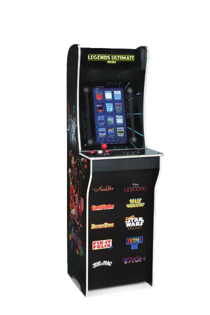
LEGENDS ULTIMATE MINI FEATURES

                   5    6   7       8    9                     10 11

                        2       1    3       4

          1. P1 JOYSTICK                 5. HDMI PORT             9. CHANNEL BUTTON
          2. REWIND                      6. USB PORT             10. POWER
          3. ATGAMES HOME BUTTON         7. RESET BUTTON         11. VOLUME ADJUSTER
          4. P1 START                    8. USB PORT

                                                                           ANCHOR TO REDUCE
         • Front                                      • Rear               TIP-OVER ACCIDENTS
                        MARQUEE LIGHT BOX                              FIXEZ LA BORNE POUR ÉVITER
                        PANNEAU LUMINEUX                                LES ACCIDENTS DE BASCULE

STEREO SPEAKERS
 HAUTS-PARLEURS

                                                                             DC POWER PORT

                                    PINBALL
                                    PINBALL BUTTONS
                                            BUTTONS
                                    BOUTONS FLIPPER

                                                                             ETHERNET PORT

    15
QUICK START GUIDE/ GUIDE DE DÉMARRAGE RAPIDE
Note: All screenshots shown are for illustration purposes only. Actual screens may vary.
Note : Les captures d’écran n’ont qu’une vocation illustrative. La disposition de l’écran de démarrage peut varier
1. Plug in AC adapter and press the Power button to turn on.
2. Use P1 joystick to select and play 150 pre-loaded games. (Note: Internet connection is not required.
The games can be played offline.)
3. Connect internet via Ethernet (Ethernet cable is not included) or Wi-Fi to play more games on ArcadeNet®.
4. To connect through Wi-Fi:
4-1. Select [Wi-Fi] under the [SETTINGS] page.
4-2. Select the Wi-Fi SSID you would like to connect to, and select [Connect].
If prompted, enter the Wi-Fi password using the on-screen keyboard and select [Submit] when done.
1. Branchez l'adaptateur secteur et appuyez sur le bouton d'alimentation pour allumer l'appareil.
2. Utilisez le joystick P1 pour sélectionner et jouer aux 150 jeux préchargés. (Remarque : une
connexion Internet n'est pas nécessaire, les jeux peuvent être joués hors ligne).
3. Connectez-vous à Internet via Ethernet (le câble Ethernet n'est pas inclus) ou Wi-Fi pour jouer à
d'autres jeux sur ArcadeNet®.
4. Pour se connecter via Wi-Fi :
4-1. Sélectionnez [Wi-Fi] dans la page [PARAMETRES].
4-2. Sélectionnez le réseau Wi-Fi auquel vous souhaitez vous connecter, puis sélectionnez [Connecter].
Si vous y êtes invité, saisissez le mot de passe Wi-Fi à l'aide du clavier à l'écran et sélectionnez
[Submit] (Soumettre) lorsque vous avez terminé.
HOW TO UPDATE FIRMWARE/
COMMENT METTRE A JOUR LE MICROPROGRAMME :
1. Power on the arcade.
2. Connect internet via Ethernet (Ethernet cable is not included) or Wi-Fi.
3. Go to [SETTINGS] and select [Version].
4. If there is a newer version, follow the instructions to download the latest firmware. Make sure the
internet connection is stable during this process.
5. Once the firmware is downloaded successfully, select [Upgrade] and the device will reboot
automatically to activate the new firmware version.
Note: If you encounter any issues on firmware update, please refer to:
https://www.atgames.net/arcades/release-notes/ or contact support@atgames.net
16HOW TO UPDATE FIRMWARE/
COMMENT METTRE A JOUR LE MICROGRAMME :
1. Mettez la borne en marche.
2. Connectez l'Internet via Ethernet (le câble Ethernet n'est pas inclus) ou Wi-Fi.
3. Allez dans [PARAMÈTRES] et sélectionnez [Version].
4. S'il existe une version plus récente, suivez les instructions pour télécharger le dernier
micrologiciel. Assurez-vous que la connexion Internet est stable pendant ce processus.
5. Une fois le micrologiciel téléchargé avec succès, sélectionnez [Upgrade] et l'appareil redémarrera
automatiquement pour activer la nouvelle version du micrologiciel.
Remarque : si vous rencontrez des problèmes lors de la mise à jour du micrologiciel, veuillez vous référer à :
https://www.atgames.net/arcades/release-notes/ ou contacter support@atgames.net
How to sign in with your ArcadeNet® account/
Comment se connecter avec votre compte ArcadeNet®
1. Go to [SETTINGS] and select [SIGN IN].
2. Sign up for a new account if you don’t have one yet.
3. Once you have an ArcadeNet® account, you can choose either to sign in with your email or with the
QR code. To sign in with your email, enter the email address and password.
1. Allez à [SETTINGS] et sélectionnez [SIGN IN].
2. Créez un nouveau compte si vous n'en avez pas encore.
3. Une fois que vous avez un compte ArcadeNet®, vous pouvez choisir de vous connecter avec votre
e-mail ou avec le code QR. Pour vous connecter avec votre e-mail, entrez l'adresse e-mail et le mot de passe.
4. To sign in with the QR-code, a smartphone or tablet is required.
5. Use a smartphone or tablet to scan the QR-code on the screen to launch the ArcadeNet® website.
You will be directed to the login page, where you can choose either to sign in with your existing
Google/Facebook account or your email.
4. Pour se connecter avec le QR-code, un smartphone est nécessaire.
5. Utilisez un smartphone pour scanner le code QR sur
l'écran afin de lancer le site Web ArcadeNet®. Vous serez
dirigé vers la page de connexion, où vous pouvez choisir de
vous connecter avec votre compte Google/Facebook existant
ou votre e-mail.
17How to sign in with your ArcadeNet® account/
Comment se connecter avec votre compte ArcadeNet®
6. You will see the authorization notification once complete. Now you can close the window and return
to your arcade. A “Success!” message will show on the arcade once signed in.
6. Vous verrez la notification d'autorisation une fois terminée. Vous pouvez maintenant fermer la
fenêtre et retourner dans votre arcade. Un message "Success !" s'affichera sur l'arcade une fois la
connexion effectuée.
HOW TO CONNECT ATGAMES BLAST! DONGLES AND CON
SOLES TO LEGENDS ULTIMATE MINI*/
COMMENT CONNECTER LES DONGLES ET CONSOLES
ATGAMES BLAST! À LA LEGENDS ULTIMATE MINI*
Step 1. Plug the “Blast! dongle” or connect “AtGames console” with HDMI cable in the
HDMI PORT, and connect USB power cord.
Step 2. Press HDMI CHANNEL button to selected HDMI source.
Step 3. The Games Menu will display on the screen. Select the game you like and play!
Étape 1. Branchez le "dongle Blast!" ou connectez la "console AtGames" avec le câble HDMI dans le
PORT HDMI, et connectez le cordon d'alimentation USB.
Étape 2. Appuyez sur le bouton HDMI CHANNEL pour sélectionner la source HDMI.
Étape 3. Le menu des jeux s'affiche à l'écran. Sélectionnez le jeu que vous aimez et jouez!
*Legends Ultimate Mini supports the following AtGames products:
2022: Legends Core Max (HA8819C).
2019: Legends Flashback (FB8660), Atari Flashback X (AR3060), Bandai Namco Arcade Blast! (WD3305
and WD3305S), Adventure Flashback Blast! (WD3308), Star Flashback Blast! (WD3309).
2018: Activision Flashback Blast! (WD3301), Atari Flashback Blast! Vol.1 (WD3302), Atari Flashback
Blast! Vol.2 (WD3303), Legends Flashback Blast! (WD3304), Bandai Namco Flashback Blast! (WD3306).
For 2018 Blast! and 2019 (WD3305S), please follow the instructions shown on the screen at SETTINGS
to pair the dongle with Legends Ultimate Mini.
18When to safely power off arcade/ Quand éteindre l'arcade en toute sécurité Do not power off the cabinet during the following: • Firmware update • Factory reset • Data cleanup • Read/write USB drive This could prevent irreversible data loss and/or damage to your cabinet and USB drives. N'éteignez pas l'armoire pendant les opérations suivantes : • Mise à jour du micrologiciel • Réinitialisation d'usine • Nettoyage des données • Lecture/écriture d'une clé USB Cela pourrait éviter une perte de données irréversible et/ou des dommages à votre cabinet et aux lecteurs USB. WARRANTY INFO The manufacturer warrants this product to be free and clear of defects in the materials and workmanship, under normal residential use and conditions, for a period of thirty (30) days from the original invoice date. Shipping and handling fees are to be paid for by the customer. To make a warranty claim, please submit a service request here: support@atgames.net. Standard warranty coverage for the AtGames Legends Ultimate Mini does not apply to and is considered invalid due to misuse, improper maintenance, self-repair, tampering, or invasive hardware modifications of any kind, and damages or dysfunction caused by shipping or non-manufacturing related causes. Note: Standard warranty services are valid with receipt from an authorized retailer. Purchases through third-party sellers and resellers do not fall under the standard warranty program. For warranty support, please contact the third-party seller or reseller where you purchased the product. Please find the latest AtGames Warranty policy at: https://www.atgames.net/arcades/warranty 19
Featured Games

Aladdin                                                   KiKi KaiKai™
Asuka & Asuka                                             Magical Drop III / The Tower
Bad Dudes vs. Dragon Ninja                                Midnight Resistance
Big Run                                                   Nastar Warrior™
Bubble Bobble™                                            Operation Wolf™
BurgerTime™ (Arcade)                                      Pinbo
Cameltry™                                                 Plus Alpha
Cybattler                                                 Pop Flamer
Desert Assault / Desert Storm Gulf War / Thunder Zone     Psychic 5
Desert War                                                Rastan™
Donald in Maui Mallard                                    Space Invaders™
Drift Out                                                 Spinmaster / Miracle Adventure
Earth Joker - U.N. Defense Force                          Storm Blade
Elevator Action Returns™                                  Super Real Darwin
Exerion                                                   Super Star Wars: Return of the Jedi
Fighter's History Dynamite / Karnov's Revenge             Tetris® Plus 2
Fix-It Felix, Jr.                                         The Jungle Book
Galmedes                                                  The Lion King
Gargoyles                                                 The Ninja Kids™
Growl™                                                    Tron
Gun & Frontier™                                           Valtric
Gun Ball / Nitro Ball                                     Volfied™
Heavy Barrel                                              Wild Western™
Joe & Mac Returns                                         Zombies Ate My Neighbors
Joe & Mac: Caveman Ninja (Arcade)                         Zoo Keeper™
                                                          And many more...

© CITY CONNECTION CO., LTD
DATA EAST and DATA EAST logo(s) are trademarks in United States and other countries or registered
trademarks in European Union and Japan of G-MODE Corporation.

© 2021 Disney. All rights reserved.
© 2021 Lucasfilm Ltd. All rights reserved.

Copyright © Piko Interactive LLC - All Rights Reserved.

SPACE INVADERS™ and other TAITO branded games included in this product are
officially licensed by TAITO CORPORATION to AtGames Interactive.
TAITO is the exclusive owner of the global intellectual property rights including
copyrights and trademarks for all TAITO branded games included in this product.

Tetris ® & © 1985~2021 Tetris Holding.
Tetris logos, Tetris theme song and Tetriminos are trademarks of Tetris Holding.
The Tetris trade dress is owned by Tetris Holding.
Licensed to The Tetris Company.
Tetris Game Design by Alexey Pajitnov.
All Rights Reserved.

                                                                                                20
Safety Notice
• Do not submerge the arcade cabinet in water or expose it to extreme heat or to strong magnetic fields.
Doing so may cause permanent damage to your device.
• Always use a dry towel to clean the cabinet and the control top.
• Transformers are suitable for indoor use only. Transformers and power supplies for toys are not
intended to be used as toys, and the use of these products by children shall be under the full
supervision of parents.
FCC Statement
This equipment has been tested and found to comply with the limits for a Class B digital device,
pursuant to part 15 of the FCC Rules. These limits are designed to provide reasonable protection
against harmful interference in a residential installation. This equipment generates, uses and can radiate
radio frequency energy and, if not installed and used in accordance with the instructions, may cause
harmful interference to radio communications. However, there is no guarantee that interference will not
occur in a particular installation. If this equipment does cause harmful interference to radio or television
reception, which can be determined by turning the equipment off and on, the user is encouraged to try
to correct the interference by one or more of the following measures:
• Reorient or relocate the receiving antenna.
• Increase the separation between the equipment and receiver.
• Connect the equipment into an outlet on a circuit different from that to which the
receiver is connected.
• Consult the dealer or an experienced radio/TV technician for help.
Caution
Any changes or modi fications to this device not explicitly approved by manufacturer could void your
authority to operate this equipment.
This device complies with part 15 of the FCC Rules. Operation is subject to the following two conditions:
(1) This device may not cause harmful interference, and (2) this device must accept any interference
received, including interference that may cause undesired operation.
For Game Host
This equipment complies with FCC radiation exposure limits set forth for an uncontrolled environment.
This equipment should be installed and operated with minimum distance 20cm between the radiator and
your body. This transmitter must not be co-located or operating in conjunction with any other antenna or
transmitter.
Warning
Adult assembly required. Due to the presence of small parts during assembly, keep out of reach of
children until assembly is complete.
21Avis de sécurité
• Ne pas immerger le cabinet d'arcade dans l'eau ou l'exposer à une chaleur extrême ou à des champs
magnétiques puissants. Cela pourrait causer des dommages permanents à votre appareil.
• Utilisez toujours une serviette sèche pour nettoyer l'armoire et le panneau de commande.
• Les transformateurs ne peuvent être utilisés qu'à l'intérieur. Les transformateurs et les alimentations
pour jouets ne sont pas destinés à être utilisés comme des jouets, et l'utilisation de ces produits par des
enfants doit se faire sous l'entière surveillance des parents.
FCC Statement
This equipment has been tested and found to comply with the limits for a Class B digital device,
pursuant to part 15 of the FCC Rules. These limits are designed to provide reasonable protection
against harmful interference in a residential installation. This equipment generates, uses and can radiate
radio frequency energy and, if not installed and used in accordance with the instructions, may cause
harmful interference to radio communications. However, there is no guarantee that interference will not
occur in a particular installation. If this equipment does cause harmful interference to radio or television
reception, which can be determined by turning the equipment off and on, the user is encouraged to try
to correct the interference by one or more of the following measures:
• Reorient or relocate the receiving antenna.
• Increase the separation between the equipment and receiver.
• Connect the equipment into an outlet on a circuit different from that to which the
receiver is connected.
• Consult the dealer or an experienced radio/TV technician for help.
Caution
Any changes or modi fications to this device not explicitly approved by manufacturer could void your
authority to operate this equipment.
This device complies with part 15 of the FCC Rules. Operation is subject to the following two conditions:
(1) This device may not cause harmful interference, and (2) this device must accept any interference
received, including interference that may cause undesired operation.
For Game Host
This equipment complies with FCC radiation exposure limits set forth for an uncontrolled environment.
This equipment should be installed and operated with minimum distance 20cm between the radiator and
your body. This transmitter must not be co-located or operating in conjunction with any other antenna or
transmitter.
Avertissement
L'assemblage par un adulte est requis. En raison de la présence de petites pièces lors de l'assemblage,
garder hors de portée des enfants jusqu'à ce que l'assemblage soit terminé.
22ISED Statement
• English: This device complies with Industry Canada license ‐ exempt RSS standard(s). Operation is
subject to the following two conditions: (1) This device may not cause interference, and (2) This device
must accept any interference, including interference that may cause undesired operation of the device.
The digital apparatus complies with Canadian CAN ICES‐3 (B)/NMB‐3(B).
• French: Le présentappareilestconforme aux CNR d'Industrie Canada applicables aux appareils radio
exempts de licence. L'exploitationestautorisée aux deux conditions suivantes: (1) l'appareil ne doit pas
produire de brouillage, et (2) l'utilisateur de l'appareildoit accepter tout brouillageradioélectriquesubi,
mêmesi le brouillageest susceptible d'encompromettre le fonctionnement.
l'appareil numérique du ciem conforme canadien peut ‐ 3 (b) / nmb ‐ 3 (b).
This device meets the exemption from the routine evaluation limits in section 2.5 of RSS 102 and
compliance with RSS 102 RF exposure, users can obtain Canadian information on RF exposure and
compliance.
cet appareil est conforme à l'exemption des limites d'évaluation courante dans la section 2.5 du cnr - 102
et conformité avec rss 102 de l'exposition aux rf, les utilisateurs peuvent obtenir des données
canadiennes sur l'exposition aux champs rf et la conformité.
This equipment complies with Canada radiation exposure limits set forth for an uncontrolled environment.
This equipment should be installed and operated with minimum distance 20cm between the radiator &
your body.
Cet équipement est conforme Canada limites d'exposition aux radiations dans un environnement non
contrôlé. Cet équipement doit être installé et utilisé à distance minimum de 20cm entre le radiateur et
votre corps.
This device meets the exemption from the routine evaluation limits in section 2.5 of RSS 102 and
compliance with RSS 102 RF exposure, users can obtain Canadian information on RF exposure and
compliance.
cet appareil est conforme à l'exemption des limites d'évaluation courante dans la section 2.5 du cnr - 102
et conformité avec rss 102 de l'exposition aux rf, les utilisateurs peuvent obtenir des données
canadiennes sur l'exposition aux champs rf et la conformité.
This equipment complies with Canada radiation exposure limits set forth for an uncontrolled environment.
This equipment should be installed and operated with minimum distance 0mm between the radiator & your
body.
Cet équipement est conforme Canada limites d'exposition aux radiations dans un environnement non
contrôlé. Cet équipement doit être installé et utilisé à distance minimum de 0mm entre le radiateur et votre
corps.
23For additional support please email: support@atgames.net
Pour plus d’aide, veuillez contacter le support AtGames : support@atgames.net
© 2021 AtGames Interactive
www.atgames.net
PO Box 1691, El Segundo, CA 90245
All rights reserved.
*Content and images are for reference only and subject to change.
*Les images du produit sont illustratives et peuvent ne pas refléter son état final.
Made in China/ Fabriqué en ChineVous pouvez aussi lire