IT Indirecte boiler Indirect calorifier Ballon échangeur IT 300 Installatie-, Gebruikers- en Servicehandleiding Installation, User and Service ...
←
→
Transcription du contenu de la page
Si votre navigateur ne rend pas la page correctement, lisez s'il vous plaît le contenu de la page ci-dessous
IT
Indirecte boiler
Indirect calorifier
Ballon échangeur
IT 300

Installatie-, Gebruikers- en Servicehandleiding
Installation, User and Service Manual
Manuel d'installation, d'utilisation et d'entretien   1019 / NL/EN/FR
                                                      0312727 / R1.0
Gegevens onderhevig aan verandering. / Data is subject to change. / Données sujettes à révision.
A.O. Smith Hoofdkantoor Europa
De Run 5305 T : +31 (0)40 294 2500
Postbus 70 T : 0800 267 6484 (gratis)
5500 AB Veldhoven info@aosmith.nl
Nederland www.aosmith.nl
A.O. Smith Water Heaters A.O. Smith Europe
Unit B7-B8 Armstong Mall T : 0870 267 6484 De Run 5305
Southwood Business Park sales@aosmith.co.uk PO Box 70
Farnborough Hampshire www.aosmith.co.uk 5500 AB Veldhoven
GU14 ONR UK The Netherlands
A.O. Smith siège France A.O. Smith siège social Europe
14, allée Charles Pathé T : 01 3975 5140 De Run 5305
18000 Bourges info@aosmith.nl Boîte postale 70
France www.aosmith.fr 5500 AB Veldhoven
Pays-BasIT 300
Inhoudsopgave / Table
of contents / Table des
matières
NL
Deze handleiding bestaat uit 3 talen.
1 - NL Handleiding IT 300 .................................................................................................... 5
2 - EN Manual IT 300 ......................................................................................................... 21
3 - FR Notice IT 300 ........................................................................................................... 37
EN
This manual consists of 3 languages.
1 - NL Handleiding IT 300 .................................................................................................... 5
2 - EN Manual IT 300 ......................................................................................................... 21
3 - FR Notice IT 300 ........................................................................................................... 37
FR
Ce notice est composé de 3 langues.
1 - NL Handleiding IT 300 .................................................................................................... 5
2 - EN Manual IT 300 ......................................................................................................... 21
3 - FR Notice IT 300 ........................................................................................................... 37
0312727_IT_300_NLENFR_V1.0, 2019-03-08 3IT 300 4 Installatie-, Service- en Gebruikershandleiding
IT 300

Lees deze handleiding            Waarschuwing
zorgvuldig                       Lees deze handleiding zorgvuldig voordat u het toestel in gebruik neemt. Het niet
                                 lezen van deze handleiding en het niet opvolgen van de instructies in deze
                                 handleiding kan leiden tot ongevallen en schade aan personen en het toestel.
                                 Copyright © 2017 A.O. Smith Water Products Company

                                 Alle rechten voorbehouden.

                                 Niets uit deze uitgave mag worden gekopieerd, verveelvoudigd en/of openbaar
                                 gemaakt door middel van druk, fotokopie of op welke andere wijze dan ook, zonder
                                 voorafgaande schriftelijke toestemming van A.O. Smith Water Products Company.

                                 A.O. Smith Water Products Company behoudt zich het recht voor de specificaties
                                 zoals vermeld in deze handleiding te wijzigen.

Handelsmerken                    Alle in deze handleiding genoemde merknamen zijn geregistreerde handelsmerken
                                 van de desbetreffende leveranciers.

Aansprakelijkheid                A.O. Smith Water Products Company is niet aansprakelijk voor claims van derden
                                 veroorzaakt door ondeskundig gebruik anders dan vermeld in deze handleiding en
                                 overeenkomstig de Algemene Voorwaarden gedeponeerd bij de Kamer van
                                 Koophandel.

                                 Zie verder de Algemene Voorwaarden. Deze kunt u kostenloos bij ons opvragen.

                                 Hoewel grote zorg is besteed aan het waarborgen van correcte en waar nodig,
                                 volledige beschrijving van de relevante onderdelen, kan het voorkomen dat de
                                 handleiding fouten en onduidelijkheden bevat.

                                 Mocht u toch fouten of onduidelijkheden in de handleiding ontdekken, dan vernemen
                                 wij dat graag van u. Het helpt ons de documentatie verder te verbeteren.

Meer informatie                  Indien u opmerkingen of vragen heeft aangaande specifieke onderwerpen die
                                 betrekking hebben op het toestel, aarzelt u dan niet contact op te nemen met:

                                 A.O. Smith Water Products Company
                                 Postbus 70
                                 5500 AB Veldhoven
                                 Nederland

                                 Telefoon:            (gratis) 0800 - AOSMITH
                                                      0800 - 267 64 84
                                 Algemeen:            +31 40 294 25 00
                                 Fax:                 +31 40 294 25 39
                                 E-mail:              info@aosmith.nl
                                 Website:             www.aosmith.nl

                                 Voor problemen met de aansluitingen op gas,- elektra- en watervoorzieningen kunt u
                                 terecht bij de leverancier/installateur van uw installatie.

0312727_IT_300_NLENFR_V1.0, 2019-03-08                                                                               5
IT 300 6 Installatie-, Service- en Gebruikershandleiding
IT 300

                                 Inhoudsopgave
           1                     Technische specificaties ............................................................................ 9
                       1.1       Vloerbelasting ........................................................................................................... 9
                       1.2       Watersamenstelling .................................................................................................. 9
                       1.3       Werkruimte ................................................................................................................ 9
                       1.4       Verpakking ................................................................................................................ 9
                       1.5       Afvoeren ................................................................................................................... 9
                       1.6       Algemene gegevens ............................................................................................... 10
                       1.7       Afmetingen .............................................................................................................. 10

           2                     Installatie .................................................................................................... 13
                       2.1       Aansluitschema ....................................................................................................... 13
                       2.2       Wateraansluitingen ................................................................................................. 13

           3                     Vullen en Aftappen .................................................................................... 15
                       3.1       Vullen ...................................................................................................................... 15
                       3.2       Aftappen ................................................................................................................. 16

           4                     Onderhoud ................................................................................................. 17
                       4.1       Onderhoud voorbereiden ........................................................................................ 17
                       4.2       Waterzijdig onderhoud ............................................................................................ 17

           5                     Garantie ...................................................................................................... 19
                       5.1       Garantie algemeen .................................................................................................            19
                       5.2       Garantie tank ..........................................................................................................       19
                       5.3       Voorwaarden installatie en gebruik .........................................................................                   19
                       5.4       Uitsluitingen ............................................................................................................     20
                       5.5       Omvang garantie ....................................................................................................           20
                       5.6       Claims .....................................................................................................................   20
                       5.7       Verplichtingen voor A.O. Smith ...............................................................................                 20

0312727_IT_300_NLENFR_V1.0, 2019-03-08                                                                                                                           7
IT 300 8 Installatie-, Service- en Gebruikershandleiding
IT 300
1 Technische specificaties
1.1 Vloerbelasting Houd in verband met het gewicht van het toestel rekening met de maximale
vloerbelasting, zie de tabel (1.6 "Algemene gegevens").
1.2 Watersamenstelling Het toestel is bedoeld om drinkwater op te warmen. Het drinkwater moet voldoen aan
de regelgeving voor drinkwater voor menselijke consumptie. In de tabel ziet u een
overzicht van de specificaties.
Specificaties water
Watersamenstelling
Hardheid > 1,00 mmol/l:
(aardalkali-ionen) Duitse hardheid > 5,6 °dH
Franse hardheid > 10,0 °fH
Britse hardheid > 7,0 °eH
> 100 mg/l CaCO3
Geleidbaarheid > 125 μS/cm
Zuurgraad (pH-waarde) 7,0 < pH-waarde < 9,5
Opmerking
Als van de in de tabel opgegeven specificaties wordt afgeweken, dan kan de
bescherming van de tank niet worden gegarandeerd (4 "Garantie").
1.3 Werkruimte In verband met de bereikbaarheid van het toestel wordt aanbevolen de volgende
afstanden in acht te nemen
bij de anode aansluitingen: 100 cm.
rondom het toestel: 50 cm.
bovenzijde van het toestel: 50 cm
1.4 Verpakking De verpakking beschermt het toestel tegen transportschade. Het
gekozen verpakkingsmateriaal is milieu vriendelijk, recyclebaar en
relatief makkelijk en milieuvriendelijk afgevoerd worden.
1.5 Afvoeren Oude afgedankte toestellen bevatten stoffen die moeten worden gerecycleerd. Houdt
u bij het afvoeren van oude afgedankte toestellen rekening met de
plaatselijke wetten met betrekking tot afvalverwerking.
Verwijder uw oude toestel dan ook nooit samen met het gewone
afval, maar lever het in bij een gemeentelijk inzameldepot voor
elektrische en elektronische apparatuur. Vraag uw
handelaar/installateur, indien nodig, om inlichtingen. Het oude
toestel moet buiten het bereik van kinderen worden opgeslagen.
0312727_IT_300_NLENFR_V1.0, 2019-03-08 9IT 300
1.6 Algemene gegevens Algemene gegevens
Eenheid IT 300
Inhoud ltr 300
Ledig gewicht kg 136
Maximale vloerbelasting kg 436
Energie-efficiëntieklasse (Energie Label) - C
Stilstandsverlies W 92
Maximale werkdruk tank kPa (bar) 1000 (10)
Maximale werkdruk warmtewisselaar kPa (bar) 2500 (25)
Maximale temperatuur tank ºC 95
Maximale temperatuur warmtewisselaar ºC 160
Anodes - 1
Vermogen warmtewisselaar kW 46
Volumestroom primair 80/60ºC l/h 1900
Drukverlies mbar 80
2
Warmte wisselend oppervlak m 1,4
1.7 Afmetingen Afmetingen
Eenheid IT 300
A Totale hoogte mm 1650
D Diameter mm 750
G Hoogte collector afvoer mm 205
H Hoogte collector toevoer mm 675
M Hoogte koudwatertoevoer mm 110
N Hoogte warmwateruitlaat mm 1460
P Hoogte reinigingsopening mm 280
R Hoogte aansluiting circulatieleiding mm 1050
S Hoogte dompelbuis/temp. sensor mm 495
T Hoogte T&P-aansluiting mm 1545
Z Hoogte aansluiting elektrisch element mm 850
1 Aansluiting koudwatertoevoer - G 1"
2 Aansluiting warmwateruitlaat - G 1"
3 Aansluiting afvoer warmtewisselaar - G 1"
4 Aansluiting aanvoer warmtewisselaar - G 1"
5 Aansluiting circulatie leiding - Rp ¾”
6 Diameter reinigings opening mm 180
7 Aansluiting T&P - Rp 1"
8 Aansluiting dompelbuis - Rp ¾”
10 Aansluiting anode - G 1¼"
11 Aansluiting elektrisch element - G 1½"
10 Installatie-, Service- en GebruikershandleidingIT 300
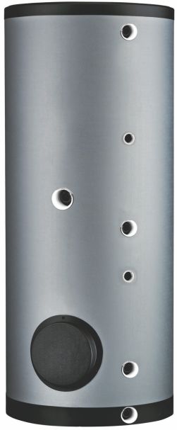
Vooraanzicht doorsnede toestel
IMD-1263 R0
0312727_IT_300_NLENFR_V1.0, 2019-03-08 11IT 300 12 Installatie-, Service- en Gebruikershandleiding
IT 300

              2                  Installatie
2.1 Aansluitschema               De figuur geeft het aansluitschema weer. Dit schema wordt gebruikt in de paragrafen
                                 waarin het eigenlijke aansluiten wordt beschreven.

                                 Installatie Schema

Legenda
1. drukreduceerventiel
    (verplicht indien de
    waterleidingdruk te
    hoog is)
2. inlaatcombinatie (verplicht)
3. T&P-ventiel (aanbevolen)
4. afsluiter (aanbevolen)
5. terugslagklep (verplicht)
6. circulatiepomp (optioneel)
9. aftrapkraan
11. service afsluiter (aanbevolen)
12. temperatuurmeter (aanbevolen)
14. tappunten

A.   koudwatertoevoer
B.   warmwaterafvoer
C.   circulatieleiding
F.   ingang warmtewisselaar
G.   uitgang warmtewisselaar

                                                                                                            IMD-1264 R0

2.2 Wateraansluitingen           Waarschuwing
                                 De installatie dient te geschieden door een erkend installateur en overeenkomstig de
                                 algemeen en plaatselijke geldende voorschriften

                      2.2.1      Koudwaterzijdig
                                 Zie (A) in het aansluitschema (2.1 "Aansluitschema").
                                 1. Indien de waterleidingdruk meer dan de voorgeschreven (1.6 "Algemene
                                     gegevens") druk is, plaats dan een goedgekeurd reduceerventiel.
                                 2. Plaats koudwaterzijdig een goedgekeurde inlaatcombinatie (2) overeenkomstig
                                     de geldende voorschriften.
                                 3. Sluit de overstortzijde van de inlaatcombinatie (2) aan op een open
                                     waterafvoerleiding.

0312727_IT_300_NLENFR_V1.0, 2019-03-08                                                                              13
IT 300
Let op
Een inlaatcombinatie is verplicht. Monteer deze zo dicht mogelijk bij het toestel.
Waarschuwing
Tussen inlaatcombinatie en het toestel mag nooit een afsluiter of terugslagklep
geplaatst worden.
2.2.2 Warmwaterzijdig
Zie (B) in het aansluitschema (2.1 "Aansluitschema").
Opmerking
Isolatie van lange warmwaterleidingen voorkomt onnodig energieverlies.
1. Optioneel: monteer een temperatuurmeter ter controle van de temperatuur van
het tapwater.
2. Aanbevolen: monteer het T&P-ventiel (3).
3. Monteer een afsluiter in de warmwaterleiding ten behoeve van servicedoeleinden.
4. Is een circulatieleiding nodig, ga dan verder met het monteren van de
circulatieleiding (2.2.3 "Circulatieleiding"). Zo niet, monteer dan de bij de
aftapkraan geleverde afdichtmoer met pakking.
2.2.3 Circulatieleiding
Zie (C) in het aansluitschema (2.1 "Aansluitschema").
Indien men direct warm water ter beschikking wil hebben bij tappunten kan een
circulatiepomp geïnstalleerd worden. Dit verhoogt het comfort en voorkomt
waterverspilling.
1. Monteer een circulatiepomp (6) met een capaciteit overeenkomend met de
grootte en weerstand van het circulatiesysteem.
2. Monteer een terugslagklep (5) na de circulatiepomp om de circulatierichting te
garanderen.
3. Monteer voor servicedoeleinden twee afsluiters (4).
4. Sluit de circulatieleiding aan volgens het aansluitschema (2.1 "Aansluitschema").
14 Installatie-, Service- en GebruikershandleidingIT 300
3 Vullen en aftappen
Installatie Schema
Legenda
1. drukreduceerventiel
(verplicht indien de
waterleidingdruk te
hoog is)
2. inlaatcombinatie (verplicht)
3. T&P-ventiel (aanbevolen)
4. afsluiter (aanbevolen)
5. terugslagklep (verplicht)
6. circulatiepomp (optioneel)
9. aftrapkraan
11. service afsluiter (aanbevolen)
12. temperatuurmeter (aanbevolen)
14. tappunten
A. koudwatertoevoer
B. warmwaterafvoer
C. circulatieleiding
F. ingang warmtewisselaar
G. uitgang warmtewisselaar
IMD-1264 R0
3.1 Vullen Om het toestel te vullen gaat u als volgt te werk:
1. Open de afsluiter in de warmwaterleiding en indien aanwezig de afsluiters (4) van
de circulatiepomp (6).
2. Sluit de aftapkraan.
3. Open het dichtstbijzijnde tappunt.
4. Open de toevoerkraan van de inlaatcombinatie (2), zodat koud water het toestel
instroomt.
5. Vul het toestel volledig. Als uit het dichtstbijzijnde tappunt een volle straal water
komt, is het toestel vol.
6. Ontlucht de gehele installatie, bijvoorbeeld door alle tappunten te openen.
7. Het toestel staat nu onder waterleidingdruk. Er mag nu geen water uit het
overstortventiel van de inlaatcombinatie en indien toegepast uit het T&P-ventiel
(3) komen. Is dit toch het geval dan kan het zijn dat:
8. Indien de waterleidingdruk groter is dan de voorgeschreven waarde (1.6
"Algemene gegevens"), plaats alsnog een drukreduceerventiel.
0312727_IT_300_NLENFR_V1.0, 2019-03-08 15IT 300
3.2 Aftappen 1. Sluit, indien aanwezig, de afsluiter in de warmwaterleiding.
2. Sluit de toevoerkraan van de inlaatcombinatie (2).
3. Open de aftapkraan.
4. Belucht het toestel (of installatie) zodat het helemaal kan leeglopen.
16 Installatie-, Service- en GebruikershandleidingIT 300
4 Onderhoud
Let op
Onderhoud mag alleen door een erkend service- en onderhoudsmonteur worden
uitgevoerd.
Bij elke onderhoudsbeurt dient de boiler waterzijdig onderhouden te worden. Het
onderhoud dient in de volgende volgorde te worden uitgevoerd.
1. Onderhoud voorbereiden
2. Waterzijdig onderhoud
3. Onderhoud afronden
Opmerking
Voor het bestellen van reserve-onderdelen is het van belang het toesteltype,
toestelmodel en het volledige serienummer van de boiler te noteren. Deze gegevens
vindt u op het typeplaatje. Aan de hand van deze informatie kunnen gegevens van
reserveonderdelen vastgesteld worden.
4.1 Onderhoud voor- De voorbereiding van het onderhoud bestaat uit het testen en controleren van enkele
bereiden componenten en deze bestaat uit de volgende stappen:
1. Test de werking van het overstort ventiel van de inlaatcombinatie. Het water dient
met een volle straal uit te stromen.
2. Controleer de afvoerleidingen van de overstortventielen en verwijder aanwezige
kalkresten.
3. Tap het toestel af.
4.2 Waterzijdig Het waterzijdig onderhoud bestaat uit het ontkalken en reinigen van de tank en het
onderhoud controleren van de anodes.
4.2.1 Ontkalken en reinigen tank
Ketelsteen- en kalkaanslag verhinderen een goede geleiding van de warmte naar het
water. Periodiek reinigen en ontkalken voorkomt vorming van deze aanslag. Hierdoor
wordt de levensduur van het toestel verlengd en bovendien het verwarmingsproces
bevorderd.
Bij bepaling van de onderhoudsfrequentie dient rekening gehouden te worden met de
snelheid van de kalkvorming. Kalkvorming is afhankelijk van de plaatselijke
watergesteldheid, het waterverbruik en de ingestelde watertemperatuur. Om
overmatige kalkaanslag te voorkomen wordt een temperatuurinstelling van maximaal
60°C aanbevolen.
Om een goede en waterdichte afsluiting van een reinigingsopening te waarborgen
moeten de pakking, sluitringen, bouten en eventueel de deksel na opening
vernieuwd worden. Bij de leverancier/fabrikant zijn hiervoor reserve-onderdelen voor
te verkrijgen.
Voor het eenvoudig ontkalken en reinigen van de tank is de boiler uitgerust met een
reinigingsopening.
0312727_IT_300_NLENFR_V1.0, 2019-03-08 17IT 300
Werkvolgorde:
1. Draai de bouten van de reiningsopening los.
2. Verwijder de deksel en de pakking.
3. Inspecteer de tank en verwijder de losse kalkaanslag en verontreinigingen.
4. Indien de kalkaanslag niet handmatig verwijderd kan worden, dient ontkalkt te
worden met een ontkalkingmiddel. Neem contact op met de leverancier/fabrikant
voor een advies over het te gebruiken ontkalkingmiddel.
5. Sluit de reinigingsopening. Om beschadiging van de tank te voorkomen dienen
de bouten aangedraaid te worden met een moment van maximaal 50 Nm.
Gebruik hiervoor geschikt gereedschap.
4.2.2 Controle anodes
Anodes zorgen voor de bescherming van de tank door zich zelf op te offeren.
Wanneer er onvoldoende anode materiaal over is kan dit leiden tot een slechte
bescherming van de tank en dat kan weer leiden tot lekkage van de tank.
1. Draai de anodes los.
2. Controleer de diameter van de anode op verschillende plekken op de anode.
Deze mag minimaal 60% van de originele diameter bedragen.
3. Indien de diameter van de anodes niet voldoet aan deze criteria dienen deze
vervangen te worden. Neem contact op met de leverancier/fabrikant voor het
bestellen van nieuwe anodes.
4. Monteer de (nieuwe) anodes.
18 Installatie-, Service- en GebruikershandleidingIT 300
5 Garantie
5.1 Garantie algemeen Indien binnen één jaar na de oorspronkelijke installatiedatum van een door
A.O. Smith geleverde boiler, na onderzoek en ter uitsluitende beoordeling van
A.O. Smith, blijkt dat een deel of onderdeel, met uitzondering van de tank, niet of niet
juist functioneert ten gevolge van fabricage- en/of materiaalfouten, zal A.O. Smith dit
deel of onderdeel vervangen of repareren.
5.2 Garantie tank
Indien binnen drie jaar na de oorspronkelijke installatiedatum van een door
A.O. Smith geleverde boiler, na onderzoek en ter uitsluitende beoordeling van
A.O. Smith, blijkt dat de stalen glasslined tank lekt ten gevolge van roest of corrosie
vanuit de waterzijdige kant, zal A.O. Smith een volledig nieuw boiler van
gelijkwaardige grootte en kwaliteit ter beschikking stellen. Op het ter vervanging
beschikbaar gestelde boiler zal een garantie gegeven worden voor de duur van de
resterende garantieperiode van de oorspronkelijk geleverde boiler. In afwijking van
het in artikel 2 bepaalde geldt, dat de garantieduur wordt teruggebracht tot één jaar
na de oorspronkelijke installatiedatum indien ongefiltreerd of onthard water door de
boiler stroomt of daarin achterblijft.
5.3 Voorwaarden De in artikel 1 en 2 bedoelde garantie geldt uitsluitend indien aan de volgende
installatie en gebruik voorwaarden is voldaan:
a. De boiler is geïnstalleerd met inachtneming van zowel de installatievoorschriften
van A.O. Smith geldend voor het specifieke model, als de plaatselijk geldende
installatie- en bouwverordeningen, voorschriften en regelingen van
overheidswege.
b. De boiler blijft geïnstalleerd op de oorspronkelijke installatieplaats.
c. Er wordt uitsluitend drinkwater gebruikt, dat te allen tijde vrij kan circuleren (voor
verwarming van zout of corrosief water is een afzonderlijk geïnstalleerde
warmtewisselaar verplicht).
d. De tank is door middel van periodiek onderhoud gevrijwaard van schadelijke
ketelsteen- en kalkaanslag.
e. De boilerwatertemperaturen zijn niet hoger dan de maximale voorgeschreven
temperatuur.
f. De waterdruk en/of warmtebelasting niet groter is dan de maxima aangegeven op
de typeplaat van de boiler.
g. De boiler is geplaatst in een niet-corrosieve atmosfeer of omgeving.
h. De boiler is voorzien van een door de daartoe bevoegde instantie goedgekeurde
inlaatcombinatie van voldoende capaciteit, niet groter dan de werkdruk als
aangegeven op de boiler en eventueel ook van een door de daartoe bevoegde
instantie goedgekeurde temperatuur- en drukontlastklep, die gemonteerd is
overeenkomstig de installatievoorschriften van A.O. Smith die van toepassing zijn
op het specifieke model boiler en voorts met inachtneming van de plaatselijke
voorschriften, verordeningen en regelingen van overheidswege.
i. De boiler moet te allen tijden voorzien zijn van kathodische bescherming. Indien
hiervoor opofferingsanodes zijn toegepast moeten deze worden vervangen en
vernieuwd indien en zodra ze voor 60% of meer verbruikt zijn. Bij toepassing van
elektrische anodes moet men ervoor zorgen dat deze continu functioneel zijn.
0312727_IT_300_NLENFR_V1.0, 2019-03-08 19IT 300
5.4 Uitsluitingen De in artikel 1 en 2 bedoelde garantie geldt niet:
a. indien de boiler door een van buiten komende oorzaak is beschadigd;
b. in geval van misbruik, verwaarlozing (met inbegrip van bevriezing), verandering,
onjuist en/of afwijkend gebruik van de boiler en wanneer gepoogd is lekken te
repareren;
c. indien verontreinigingen of andere deeltjes de tank in hebben kunnen stromen;
d. indien de geleidbaarheid van het water minder is dan 125 μS/cm en/of de
hardheid (aardalkali-ionen) van het water minder is dan 1,00 mmol/lt;
e. indien ongefilterd, gerecirculeerd water door de boiler stroomt of in de boiler
opgeslagen wordt;
f. indien gepoogd is zelf een defecte boiler te repareren.
5.5 Omvang garantie De verplichtingen van A.O. Smith krachtens de gegeven garantie gaat niet verder
dan kosteloze levering af magazijn van de te vervangen delen of onderdelen
respectievelijk boiler. vervoers-, arbeids-, installatie- en andere met de vervanging
verband houdende kosten komen niet voor rekening van A.O. Smith.
5.6 Claims Een claim gebaseerd op de gegeven garantie moet worden gedeponeerd bij de
handelaar bij wie de boiler is gekocht of bij een andere handelaar die de producten
van A.O. Smith Water Products Company verkoopt. Het onderzoek van de boiler
bedoeld in de artikelen 1 en 2 zal plaatsvinden in een laboratorium van A.O. Smith.
5.7 Verplichtingen voor Met betrekking tot haar boilers respectievelijk de ter vervanging geleverde (delen of
A.O. Smith onderdelen van de) boilers, wordt door A.O. Smith geen andere garantie of waarborg
gegeven dan de garantie zoals uitdrukkelijk in dit certificaat verwoord.
A.O. Smith is krachtens de gegeven garantie of anderszins niet aansprakelijk voor
schade aan personen of zaken, veroorzaakt door (delen of onderdelen,
respectievelijk de stalen glasslined tank van) een door haar (ter vervanging)
geleverde boiler.
20 Installatie-, Service- en GebruikershandleidingIT 300
Read this manual carefully Warning
Read this manual carefully before starting the water heater. Failure to read the
manual and to follow the printed instructions may lead to personal injury and
damage to the water heater.
Copyright © 2017 A.O. Smith Water Products Company
All rights reserved.
Nothing from this publication may be copied, reproduced and/or published by
means of printing, photocopying or by whatsoever means, without the prior written
approval of A.O. Smith Water Products Company.
A.O. Smith Water Products Company reserves the right to modify specifications
stated in this manual.
Trademarks Any brand names mentioned in this manual are registered trademarks of their
respective owners.
Liability A.O. Smith Water Products Company accepts no liability for claims from third
parties arising from unauthorised use, use other than that stated in this manual, and
use other than in accordance with the General Conditions registered at the
Chamber of Commerce.
Refer further to the General Conditions. These are available on request, free of
charge.
Although considerable care has been taken to ensure a correct and suitably
comprehensive description of all relevant components, the manual may
nonetheless contain errors and inaccuracies. Should you detect any errors or
inaccuracies in the manual, we would be grateful if you would inform us. This helps
us to further improve our documentation.
More information If you have any comments or queries concerning specific aspects related to the
water heater, then please do not hesitate to contact:
A.O. Smith Water Products Company:
PO Box 70
5500 AB Veldhoven
The Netherlands
Telephone: (free) 0870 - AOSMITH
0870 - 267 64 84
General: +31 40 294 25 00
Fax: +31 40 294 25 39
E-mail: info@aosmith.nl
Website: www.aosmith.co.uk
In the event of problems with your gas, electricity or water supply connections,
please contact the supplier/installation engineer of your installation.
0312727_IT_300_NLENFR_V1.0, 2019-03-08 21IT 300 22 Installation, Service and User Manual
IT 300

                          Table of contents
           1                     Technical specifications ........................................................................... 25
                       1.1       Floor load ................................................................................................................    25
                       1.2       Water composition ..................................................................................................           25
                       1.3       Working clearance ..................................................................................................           25
                       1.4       Packaging ...............................................................................................................      25
                       1.5       Disposal ..................................................................................................................    25
                       1.6       General specifications .............................................................................................           26
                       1.7       Dimensions .............................................................................................................       26

           2                     Installation ................................................................................................. 29
                       2.1       Installation diagram ................................................................................................. 29
                       2.2       Water connections .................................................................................................. 29

           3                     Filling and Draining .................................................................................... 31
                       3.1       Filling ...................................................................................................................... 31
                       3.2       Draining .................................................................................................................. 32

           4                     Maintenance ............................................................................................... 33
                       4.1       Preparation for maintenance ................................................................................... 33
                       4.2       Water-side maintenance ......................................................................................... 33

           5                     Warranty ..................................................................................................... 35
                       5.1       General warranty ....................................................................................................          35
                       5.2       Tank warranty .........................................................................................................        35
                       5.3       Conditions for installation and use ..........................................................................                 35
                       5.4       Exclusions ...............................................................................................................     36
                       5.5       Scope of warranty ...................................................................................................          36
                       5.6       Claims .....................................................................................................................   36
                       5.7       Obligations of A.O. Smith ........................................................................................             36

0312727_IT_300_NLENFR_V1.0, 2019-03-08                                                                                                                          23
IT 300 24 Installation, Service and User Manual
IT 300
1 Technical specifications
1.1 Floor load Allow for the water heater's weight and the maximum floor load; refer to the table
(1.6 "General specifications").
1.2 Water composition The water heater is intended for heating drinking water. The drinking water must
comply with the regulations governing drinking water for human consumption. The
table gives an overview of the specifications.
Water specifications
Water composition
Hardness > 1,00 mmol/l:
(alkaline earth ions) German hardness > 5,6 °dH
French hardness > 10,0 °fH
English hardness > 7,0 °eH
> 100 mg/l CaCO3
Conductivity > 125 μS/cm
Acidity (pH value) 7,0 < pH value < 9,5
Note
If the water specifications deviate from those stated in the table, then the tank
protection cannot be guaranteed (4"Warranty").
1.3 Working clearance For access to the water heater, it is recommended that the following clearances are
observed:
around the anode connection: 100 cm.
around the water heater: 50 cm.
top of the water heater: 50 cm
1.4 Packaging The packaging prevents damage to the appliance during transport.
The packaging material chosen is environmentally friendly, recyclable
and relatively easy to dispose of in an environmentally aware way.
1.5 Disposal Old end-of-life appliances contain materials that need to be recycled. When disposing
of old devices that have reached the end of their service life, you
should take account of local legislation relating to waste disposal.
You must therefore never dispose of your old appliance together
with regular waste, but should and it into a municipal waste
collection depot for electrical and electronic equipment. Ask your
dealer/installation engineer for advice if necessary. The old
appliance must be stored out of reach of children.
0312727_IT_300_NLENFR_V1.0, 2019-03-08 25IT 300
1.6 General specifications General specifications
Unit IT 300
Contents litres 300
Empty weight kg 136
Maximum floor load kg 436
Energy Efficiency Class (Energy Label) - C
Heat Loss W 92
Maximum operating pressure tank kPa (bar) 1000 (10)
Maximum operating pressure heat exchanger kPa (bar) 2500 (25)
Maximum water temperature tank ºC 95
Maximum water temperature heat exchanger ºC 160
Maximum operating pressure Vented kPa (bar) 800 (8)
Maximum operating pressure Unvented kPa (bar) 550 (5.5)
Anodes - 1
Capacity heat exchanger kW 46
Primary flow 80/60ºC l/h 1900
Pressure loss mbar 80
2
Heat exchange surface m 1,4
1.7 Dimensions Dimensions
Unit IT 300
A Total height mm 1650
D Diameter mm 750
G Height heat exchanger outlet mm 205
H Height heat exchanger inlet mm 675
M Height cold water inlet mm 110
N Height warm water outlet mm 1460
P Height inspection opening mm 280
R Height connection circulation mm 1050
S Height immersion well mm 495
T Height T&P connection mm 1545
Z Height electrical element mm 850
1 Cold water inlet - G 1"
2 Warm water outlet - G 1"
3 Heat exchanger outlet - G 1"
4 Heat exchanger inlet - G 1"
5 Connection circulation - Rp ¾"
6 Diameter inspection opening mm 180
7 T&P connection - Rp 1
8 Immersion well - Rp ¾"
10 Anode connection - G 1¼" "
11 Electrical element connection - G 1½"
26 Installation, Service and User ManualIT 300
Front sectional view of the appliance
IMD-1263 R0
0312727_IT_300_NLENFR_V1.0, 2019-03-08 27IT 300 28 Installation, Service and User Manual
IT 300

              2                    Installation
2.1 Installation diagram           This figure shows the installation diagram. This diagram is referred to in the sections
                                   describing the actual connection procedure.

                                   Installation Diagram
Legend
1. pressure relief valve
    (mandatory if mains water
    pressure is too high)
3. T&P-valve
4. stop valve (recommended)
5. non-return valve (mandatory)
6. circulation pump (optional)
9. drain valve
11. service stop valve
12. temperature gauge (optional)
14. draw-off points
15. expansion valve (mandatory)
16. expansion vessel (mandatory)

A.   cold water supply
B.   hot water supply
C.   circulation pipe
F.   inlet heat exchanger
G.   outlet heat exchanger

                                                                                                                  IMD-1265 R0

2.2 Water connections              Warning
                                   The installation should be carried out by a competent person, in compliance with
                                   general and locally applicable regulations.

                       2.2.1       Cold water side
                                   See (A) in the installation diagram (2.1 "Installation diagram").
                                   1. Fit an approved stop valve (4) on the cold water side as required by the
                                      applicable regulations.
                                   2. The maximum working pressure of the water heater is 10 bar. Because the
                                      pressure in the water pipe at times can exceed 10 bar, you must fit an approved
                                      pressure-reducing valve (1).
                                   3. Fit a non-return valve (5) and an expansion vessel (16).
                                   4. Fit an expansion valve (15) and connect the overflow side to an open waste water
                                      pipe.

0312727_IT_300_NLENFR_V1.0, 2019-03-08                                                                                    29
IT 300
2.2.2 Hot Water side
See (B) in the installation diagram (2.1 "Installation diagram").
Note
Insulating long hot water pipes prevents unnecessary energy loss.
1. Optional: fit a temperature gauge (12) so you can check the temperature of the
tap water.
2. Fit the T&P valve (3).
3. Fit a stop valve (11) in the hot water outlet pipe for servicing.
2.2.3 Circulation pipe
See (C) in the installation diagram (2.1 "Installation diagram").
If an immediate flow of hot water is required at draw-off points, a circulation pump
can be installed. This improves comfort, and reduces water wastage.
1. Fit a circulation pump (6) of the correct capacity for the length and resistance of
the circulation system.
2. Fit a non-return valve (5) after the circulation pump to guarantee the direction of
circulation.
3. Fit two stop valves for servicing (4).
4. Connect the circulation pipe according to the installation diagram (2.1 "Installation
diagram").
30 Installation, Service and User ManualIT 300
3 Filling and draining
Installation Diagram
Legend
1. pressure relief valve
(mandatory if mains water
pressure is too high)
3. T&P-valve
4. stop valve (recommended)
5. non-return valve (mandatory)
6. circulation pump (optional)
9. drain valve
11. service stop valve
12. temperature gauge (optional)
14. draw-off points
15. expansion valve (mandatory)
16. expansion vessel (mandatory)
A. cold water supply
B. hot water supply
C. circulation pipe
F. inlet heat exchanger
G. outlet heat exchanger
IMD-1265 R0
3.1 Filling To fill the water heater, proceed as follows:
1. Open the stop valve (11) in the hot water pipe and, if present, the stop valves (4)
for the circulation pump (6).
2. Close the drain valve (9).
3. Open the nearest hot water draw-off point (14).
4. Open the stop valve (4) on the cold water side (A) so that cold water flows into
the water heater.
5. Completely fill the water heater. When a full water jet flows from the nearest
draw-off point, the water heater is full.
6. Bleed the entire installation of air, for example by opening all draw-off points.
7. The water heater is now under water supply pressure. There should now be no
water coming out of the inlet combination expansion valve or (if used) out of the
T&P valve (3). If there is, the cause might be:
- The water supply pressure is greater than the specified value (1.6 "General
specifications"). Rectify this by fitting a pressure reducing valve (1).
- The expansion valve in the protected cold supply set-up is defective or
incorrectly fitted.
0312727_IT_300_NLENFR_V1.0, 2019-03-08 31IT 300
3.2 Draining 1. Close the stop valve (4) between the cold water head tank and the cold water
inlet (A).
2. Open the drain valve (9).
3. Bleed the water heater (or installation) so that it drains completely.
32 Installation, Service and User ManualIT 300
4 Maintenance
Warning
Maintenance may only be carried out by a competent person.
At each service, the water heater undergoes maintenance on water side. The
maintenance must be carried out in the following order.
1. Preparation for maintenance
2. Water-side maintenance
3. Finalizing maintenance
Note
Before ordering spare parts, it is important to write down the installation type, water
heater model and the full serial number of the water heater. These details can be
found on the rating plate. Only by ordering with this information can you be sure
receiving the correct spare parts.
4.1 Preparation for The preparation for maintenance consists out of testing and checking if all
maintenance components are still working properly, complete the following steps:
1. Test the operation of the overflow valve of the protected cold supply setup. The
water should discharge out.
2. Check the drainage pipes from the discharge points of all valves and remove any
scale deposits that may be present.
3. Drain the water heater.
4.2 Water-side Water-side maintenance consists of descaling and cleaning the tank and checking
maintenance the anodes.
4.2.1 Descaling and cleaning the tank
Scale and lime build-up prevent effective conduction of the heat to the water.
Periodic cleaning and descaling prevents build-up of these deposits. This increases
the service life of the water heater, and also improves the heating process.
Take the rate of scale formation into account when deciding on the service interval.
Scale formation depends on the local water composition, the water consumption and
the water temperature setting. A water temperature setting of maximum 60°C is
recommended for the prevention of excessive scale build-up.
To guarantee a good, watertight seal around the cleaning opening, replace the
gasket, washers, bolts and, if necessary, the lid with new parts before reassembly.
Spare parts are obtainable from the supplier/manufacturer.
To simplify descaling and cleaning of the tank, the water heater is equipped with a
cleaning opening.
0312727_IT_300_NLENFR_V1.0, 2019-03-08 33IT 300
Work order:
1. Undo bolts from the cover.
2. Remove cover and the gasket.
3. Inspect the tank and remove the loose scale deposits and contamination.
4. If the scale cannot be removed by hand, descale the water heater with a
descaling agent. Contact the supplier/manufacturer for advice on what descaling
agent to use.
5. Close the cleaning opening. To avoid damage to the tank, tighten the bolts that
fasten the lid, with a torque no greater than 50 Nm. Use suitable tools for this.
4.2.2 Checking anodes
Anodes ensure the protection of the tank by sacrificing themselves. Insufficient anode
material may lead to poor protection and, hence, leakage of the tank.
1. Loosen the anodes one by one.
2. Check the diameter of each anode in different places. The diameter must be at
least 60% of the original diameter.
3. If the diameter is less than the minimum, the anode must be replaced. Please
contact the supplier/manufacturer for ordering new anodes.
4. Mount the (new) anodes.
34 Installation, Service and User ManualIT 300
5 Warranty
5.1 General warranty If within one year of the original installation date of a water heater supplied by
A.O. Smith, following verification, and at the sole discretion of A.O. Smith, an
assembly or part (with exclusion of the tank) proves to be defective or fails to function
correctly due to manufacturing and/or material defects, then A.O. Smith shall repair
or replace this assembly or part.
5.2 Tank warranty If within 3 years of the original installation date of a water heater supplied by
A.O. Smith, following verification, and at the sole discretion of A.O. Smith, the glass-
lined steel tank proves to be leaking due to rust or corrosion occurring on the water
side, then A.O. Smith shall offer to replace the defective water heater with an entirely
new water heater of equivalent size and quality The warranty period given on the
replacement water heater shall be equal to the remaining warranty period of the
original water heater that was supplied. Notwithstanding that stated earlier in this
article, in the event that unfiltered or softened water is used, or allowed to stand in
the water heater, the warranty shall be reduced to one year from the original
installation date.
5.3 Conditions for The warranty set out in articles 1 and 2 will apply solely under the following
installation and use conditions:
a. The water heater is installed under strict adherence to A.O. Smith installation
instructions for the specific model, and the relevant government and local
authority installation and building codes, rules and regulations in force at the time
of installation.
b. The water heater remains installed at the original site of installation.
c. The water heater is used exclusively with drinking water, which at all times can
freely circulate (a separately installed heat exchanger is mandatory for heating
saline water or corrosive water).
d. The tank is safeguarded against harmful scaling and lime build-up by means of
periodic maintenance.
e. The water temperatures in the heater do not exceed the maximum setting.
f. The water pressure and/or heat load do not exceed the maximum values stated
on the water heater rating plate.
g. The water heater is installed in a non-corrosive atmosphere or environment.
h. The water heater is connected to a protected cold supply arrangement, which is:
approved by the relevant authority; with sufficient capacity for this purpose;
supplying a pressure no greater than the working pressure stated on the water
heater; and where applicable by a likewise approved temperature and pressure
relief valve, fitted in accordance with installation instructions of A.O. Smith
applying to the specific model of water heater, and further in compliance with the
government and local authority installation and building codes, rules and
regulations.
i. The water heater is at all times fitted with cathodic protection. If sacrificial anodes
are used for this, these must be replaced and renewed when, and as soon as,
they are 60% or more consumed. When power anodes are used, it is important to
ensure that they continue to work properly.
0312727_IT_300_NLENFR_V1.0, 2019-03-08 35IT 300
5.4 Exclusions The warranty set out in articles 1 and 2 will not apply in the event of:
a. damage to the water heater caused by an external factor;
b. misuse, neglect (including frost damage), modification, incorrect and/or
unauthorised use of the water heater and any attempt to repair leaks;
c. contaminants or other substances having been allowed to enter the tank;
d. the conductivity of the water being less than 125 μS/cm and/or the hardness
(alkaline-earth ions) of the water being less than 1.00 mmol/lit
e. unfiltered, recirculated water flowing through or being stored in the water heater;
f. any attempts at repair to a defective water heater other than by an approved
service engineer.
5.5 Scope of the The obligations of A.O. Smith pursuant to the specified warranty are limited to free
warranty delivery from the warehouse of the replacement assemblies, parts or water heater,
respectively. Shipping, labour, installation and any other costs associated with the
replacement will not be accepted by A.O. Smith.
5.6 Claims A claim on grounds of the specified warranty must be submitted to the dealer from
whom the water heater was purchased, or to another authorised dealer for
A.O. Smith Water Products Company products. Inspection of the water heater as
referred to in articles 1 and 2 shall take place in one of the laboratories of A.O. Smith.
5.7 Obligations of A.O. Smith grants no other warranty or guarantee over its water heaters nor the
A.O. Smith (assemblies or parts of) water heaters supplied for replacement, other than the
warranty expressly set out in this Certificate.
Under the terms of the supplied warranty, A.O. Smith is not liable for damage to
persons or property caused by (assemblies or parts, or the glass-lined steel tank of) a
(replacement) water heater that it has supplied.
36 Installation, Service and User ManualIT 300
Veuillez lire attentivement ce Attention
manuel Lisez attentivement ce manuel d'instructions avant de mettre l'appareil en service. Ce
manuel d'instructions doit être lu scrupuleusement et les instructions de ce manuel
d'instructions doivent être suivies sous peine d'accidents et de dégâts matériels et/ou
de blessures corporelles.
Droits d'auteur © 2017 A.O. Smith Water Products Company
Tous droits réservés.
Aucune partie de ce document ne peut être copiée, dupliquée et/ou diffusée par
impression, photocopie ou tout autre moyen de reproduction, sans l'accord écrit
préalable de A.O. Smith Water Products Company.
A.O. Smith Water Products Company se réserve le droit de modifier les
spécifications de ce manuel d'instructions.
Marques de commerce Toutes les marques mentionnées dans ce manuel d'instructions sont des marques
déposées par les fournisseurs concernés.
Responsabilité A.O. Smith Water Products Company n'est pas responsable des réclamations de
tiers liées à une utilisation inadéquate autre que celle mentionnée dans ce manuel
d'instructions et conformément aux Conditions générales déposées auprès de la
Chambre de commerce.
Voir les Conditions générales pour plus de détails. Celles–ci peuvent être obtenues
gratuitement sur simple demande.
Bien que nous ayons apporté le plus grand soin à la réalisation de descriptions
correctes et, le cas échéant, complètes des composants importants, il se peut que le
manuel d'instructions comporte des erreurs et des imprécisions.
Si vous découvrez des erreurs ou des imprécisions dans ce manuel d'instructions,
n'hésitez pas à nous en faire part. Votre aide contribuera à améliorer la
documentation.
Pour plus d'informations Si vous avez des remarques ou des questions concernant des sujets spécifiques qui
ont trait à l'appareil, n'hésitez pas à prendre contact avec :
A.O. Smith Water Products Company
Case postale 70
5500 AB Veldhoven
Pays-Bas
Téléphone (gratuit) 008008 - AOSMITH
008008 - 267 64 84
Général: +31 40 294 25 00
Fax: +31 40 294 25 39
E-mail : info@aosmith.nl
Site web : www.aosmith.fr
En cas de problèmes de raccordement aux installations de gaz, d'électricité et d'eau,
adressez-vous au fournisseur/à l'installateur de votre installation.
0312727_IT_300_NLENFR_V1.0, 2019-03-08 37IT 300 38 Notice d’installation, Mode d’emploi, Notice d’entretien
IT 300

                                 Table des matières
           1                     Spécifications techniques ........................................................................ 41
                       1.1       Charge maximale au sol l'appareil ..........................................................................                 41
                       1.2       Composition de l'eau ...............................................................................................         41
                       1.3       Espace de travail ....................................................................................................       41
                       1.4       Emballage ...............................................................................................................    41
                       1.5       Élimination ..............................................................................................................   41
                       1.6       Données générales .................................................................................................          42
                       1.7       Dimensions .............................................................................................................     42

           2                     Installation ................................................................................................. 45
                       2.1       Schéma de raccordement ....................................................................................... 45
                       2.2       Raccordement hydraulique ..................................................................................... 45

           3                     Remplissage é Vidange ............................................................................ 47
                       3.1       Remplissage ........................................................................................................... 47
                       3.2       Vidange ................................................................................................................... 47

           4                     Effecteur l'entretien ................................................................................... 49
                       4.1       Préparer l'entretien .................................................................................................. 49
                       4.2       Entretien côté eau ................................................................................................... 49

           5                     Garantie ...................................................................................................... 51
                       5.1       Garantie générale ...................................................................................................        51
                       5.2       Garantie sur la cuve ................................................................................................        51
                       5.3       Conditions d'installation et d'utilisation ....................................................................              51
                       5.4       Exclusions ...............................................................................................................   52
                       5.5       Portée de la garantie ...............................................................................................        52
                       5.6       Réclamations ..........................................................................................................      52
                       5.7       Obligations de A.O. Smith .......................................................................................            52

0312727_IT_300_NLENFR_V1.0, 2019-03-08                                                                                                                        39
IT 300 40 Notice d’installation, Mode d’emploi, Notice d’entretien
IT 300
1 Spécifications techniques
1.1 Charge maximale au Tenez compte de la charge maximale exercée sur le sol par le poids de l'appareil,
sol de l'appareil voir le tableau (1.6 "Données générales").
1.2 Composition de l'eau L'appareil est destiné à réchauffer de l'eau potable. L'eau potable doit être conforme
aux régulations d'eau potable pour la consommation humaine. Vous trouverez, dans
le tableau, un aperçu des spécifications.
Spécifications de l'eau
Composition de l'eau
Dureté > 1,00 mmol/l:
(ions terrestres alcalins) Dureté allemande > 5,6 °dH
Dureté française > 10,0 °fH
Dureté britannique > 7,0 °eH
> 100 mg/l CaCO3
Conductivité > 125 μS/cm
Acidité (valeur de pH) 7,0 < valeur pH < 9,5
Note
Si l'on s'écarte des spécifications indiquées dans le tableau, la protection de la cuve
ne pourra plus être garantie (4 "Garantie").
1.3 Espace de travail En ce qui concerne l'accessibilité de l'appareil, il est recommandé de tenir compte
des distances minimales suivantes:
au niveau des raccords d'anode: 100 cm.
autour de l'appareil : 50 cm
dimensions de l'appareil: 50 cm
1.4 Emballage L'emballage protège l'appareil durant son transport. Il est fabriqué
dans un matériau écologique et recyclable, qui s'achemine de
manière relativement aisée et dans le respect de l'environnement.
1.5 Élimination Les appareils usés contiennent des matières qui doivent être recyclées. Pour
l'évacuation de ces appareils, vous devez tenir compte des lois
locales en vigueur concernant le traitement des déchets.
Il ne faut donc jamais jeter votre ancien appareil avec les déchets
ordinaires, mais le livrer au site communal de collecte des
appareils électriques et électroniques. Si besoin, demandez des
renseignements au commerçant/à l'installateur. L'ancien appareil
doit être stocké à un endroit hors de portée des enfants.
0312727_IT_300_NLENFR_V1.0, 2019-03-08 41IT 300
1.6 Données générales Données générales
Unité IT 300
Capacité l. 300
Poids à vide kg 136
Charge maximale au sol de l'appareil kg 436
Class Efficacité Énergétique (Étiquette d’Énergie) - C
Consommation d’entretien W 92
Pression de fonctionnement max. du cuve kPa (bar) 1000 (10)
Pression de fonctionnement max. du serpentin kPa (bar) 2500 (25)
Température maximale du cuve ºC 95
Température maximale du serpentin ºC 160
Nombre d'anodes - 1
Capacité du serpentin kW 46
Débit primaire 80/60ºC l/h 1900
Perte de pression mbar 80
2
Surface du serpentin m 1,4
1.7 Dimensions Dimensions
Unité IT 300
A Hauteur totale mm 1650
D Diamètre mm 750
G Hauteur sortie du échangeur mm 205
H Hauteur entrée du échangeur mm 675
M Hauteur de l'alimen. en eau froide mm 110
N Hauteur de la sortie d'ean chaude mm 1460
P Hauteur de regard de nettoyage mm 280
R Hauteur connexion de circulation mm 1050
S Hauteur du raccord immersion ainsi mm 495
T Hauteur du raccord de la soupape T&P mm 1545
Z Hauteur du raccord de élément électrique mm 850
1 Raccord. d'alimentation en eau froide - G 1"
2 Raccord de sertie d'eau chaude - G 1"
3 Raccord de la sortie du échangeur - G 1"
4 Raccord de l'entrée du échangeur - G 1"
5 Raccord de circulation - Rp ¾"
6 Diamètre de nettoyage mm 180
7 Raccord de la soupape T&P - Rp 1"
8 Raccord immersion ainsi - Rp ¾"
10 Raccord anode - G 1¼"
11 Raccord de élément électrique - G 1½"
42 Notice d’installation, Mode d’emploi, Notice d’entretienVous pouvez aussi lire