KEPLER LFSn Notice d'instructions User's guide Gebrauchsanweisungen - II 3G Ex nA IIC T4 Gc II 2D Ex tb IIIC T80 C Db IP66/IP68 - Sammode
←
→
Transcription du contenu de la page
Si votre navigateur ne rend pas la page correctement, lisez s'il vous plaît le contenu de la page ci-dessous
KEPLER
       LFSn

       Notice d'instructions
       User’s guide
       Gebrauchsanweisungen

                                 II 3G Ex nA IIC T4 Gc
                                 II 2D Ex tb IIIC T80°C Db IP66/IP68

Sammode SA                                                             Notice KEPLER rév.J
24, rue des Amandiers – F 75020 Paris            1/12                         Janvier 2017
FR

Rappel des indications pour le marquage du matériel

Indications for the marking of the equipment

Angaben für die Markierung der Leuchte

-     Sammode – 24, rue des Amandiers – F 75020 PARIS.
-     LFSn …
-     Année de fabrication / Manufacturing year / Herstellungsjahr
-          II 2D Ex tb IIIC T80°C Db IP66/IP68 / INERIS 03 ATEX 0011X
-         II 3G Ex nA IIC T4 Gc / INERIS 03 ATEX 3004X
-     IECEx INE 13.0029X
-     Tamb : -20 °C / +40°C
-     AVERTISSEMENTS :
         « DANGER POTENTIEL DE CHARGES ÉLECTROSTATIQUES - VOIR INSTRUCTIONS»
         « NE PAS OUVRIR SOUS TENSION »
         « NE PAS OUVRIR SI UNE ATMOSPHERE EXPLOSIVE EST PRESENTE »

          « POTENTIAL ELECTROSTATIC CHARGING HAZARD – SEE INSTRUCTIONS»
          « DO NOT OPEN WHEN ENERGIZED »
          « DO NOT OPEN IN CASE OF POTENTIAL EXPLOSIVE ATMOSPHERE »

         « VORSICHT STATISCHE LADUNG - SIEH ANWEISUNGEN »
          « NICHT UNTER SPANNUNG ÖFFNEN »
         « BEI EXPLOSIONSGEFÄHRDETER ATMOSPHÄRE NICHT ÖFFNEN »
-     INERIS 03ATEX0011 / INERIS 03ATEX3004
                        Ballast             Puissance          Un      Fn        In                Marquage
                                                               (V)    (Hz)     (mA)
                        EC 20 B 90          1 x 18W                             140
                        EC 36 B501K         1 x 36W                             240
                        L58 TL2             1 x 58W                             360
      Ferromagnétique   EC 65 B140          1 x 58W            230      50      360
                        EC 36 B501K         2 x 18W                             230
                        EC 36 B501K         2 x 36W                             380
                        EC 65 B140          2 x 58W                             600
                                            1 x 18W                              90
                        PC PRO              1 x 36W                             160
                                                                                      II 3G Ex nA IIC T4 Gc
                        PC Industry         1 x 58W                             360
                                                           220-240   0/50/60          II 2D Ex tb IIIC T80°C Db IP66/IP68
                                            2 x 18W                             180
                                            2 x 36W                             320
    Electronique                            2 x 58W                             520
                        EL s                1 x 18W                              90
                                            1 x 36W                             160
                                            1 x 58W                             360
                                                           220-240   50/60
                                            2 x 18W                             180
                                            2 x 36W                             320
                                            2 x 58W                             520

Version Française………………………                    Pages 3 à 5

English Version…………………………                     Pages 6 to 8

Deutsch Version………………………...                   Pages 9 - 11

Sammode SA                                                                                 Notice KEPLER rév.J
24, rue des Amandiers – F 75020 Paris                   2/12                                      Janvier 2017
FR
Avant-propos
Les instructions qui suivent doivent être lues conjointement avec, entre autres, les normes EN 60079-17 (Atmosphères
explosives - Partie 17 : inspection et entretien des installations électriques), EN 60079-14 (Matériel électriques pour
atmosphères explosives gazeuses - Partie 14: Installations électriques dans les emplacements dangereux (autres que les
mines)), NF C 15100, EN 60079-19 (Atmosphères explosives - Partie 19 : réparation, révision et remise en état de
l'appareil), les règlements, les décrets, les arrêtés, les lois, les directives, les circulaires d’applications, les autres normes
concernées, les règles de l’art et tout autre document (édité par l’INRS ou l’INERIS, par exemple) concernant le lieu
d’installation concerné. Le non-respect de ceux-ci ne saurait engager la responsabilité de Sammode. L’utilisateur devra
avoir connaissance des risques induits par les courants électriques et des caractéristiques physiques et chimiques des
poussières présentes dans l’installation. Cela inclus, entre autres, la vérification de la compatibilité entre les
températures de surface du luminaire et les températures d’inflammation de ces poussières. Il en va de même pour les
gaz, vapeurs ou brouillards combustibles.
Ce luminaire est destiné aux zones où des atmosphères explosibles poussiéreuses et/ou gazeuses peuvent être
présentes :
zone 21, zone 2.
Les définitions des zones peuvent-être les suivantes :
- zone 21 : Emplacement dans lequel une atmosphère explosive sous forme d'un nuage de poussières combustibles
dans l'air est susceptible de se former occasionnellement en service normal.
- zone 2 : Région dans laquelle il n’est pas probable qu’une atmosphère explosive gazeuse apparaisse en
fonctionnement normal et où, si elle apparaît, il est probable que ce soit seulement de façon peu fréquente et
qu’elle n’existera que pour une courte période.
La détermination et la délimitation de ces zones sont de la responsabilité et du ressort du responsable du site.
Instructions pour une mise en œuvre sans risques
(réalisée par du personnel compétent)
1
1 Installation
Toute intervention sur le luminaire sera faite hors-tension.
1.1 Mettre en place les bandeaux de fixation seuls.
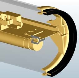
1.2 Avant montage de l'appareil dans ses 2 bandeaux :
a) dévisser la vis centrale , libérant ainsi la platine interne ,
b) enlever le flasque mobile ,
c) tirer par ce même coté la platine (en n’en faisant sortir que 20 cm) en
appliquant un mouvement tel que décrit par la flèche (fig. 1). Monter le ou les 8
tubes fluorescents sur les douilles,
d) raccorder (voir § 2), -1-
e) pour refermer le luminaire, pousser la platine à fond, puis la replacer
sous les butées . Une butée élastique en bout de platine, compressée
quand celle-ci est rentrée, la verrouillera sous les butées .
1.3 Mettre l'appareil dans ses bandeaux préalablement fixés selon le § 1.1.
1.4 Mettre en place le flasque mobile afin qu'il vienne coiffer correctement le 2
joint. -2-
1.5 Visser la vis centrale en veillant à une application correcte du flasque
mobile sur le joint. Terminer le serrage de la vis centrale pour assurer l'herméticité de l'appareil. Eviter un
serrage excessif (couple de 1.7 N.m + 0/- 0,1 à appliquer sur la vis centrale). Pour être certain de la qualité du
serrage, comparez la déformation de votre joint (sous la vis) avec celles des photos suivantes :
Bon
1.6 Serrer le chapeau de PE (couple de 5 N.m +/- 0,5).
1.7 En ouvrant les bandeaux de fixation, faire tourner l'appareil pour le placer dans l'axe d'éclairement désiré.
Sammode SA Notice KEPLER rév.J
24, rue des Amandiers – F 75020 Paris 3/12 Janvier 2017FR
Raccordement (A effectuer hors tension)
2.1 Dégainer le câble d’alimentation de 35 à 40 mm (selon qu’il soit souple ou rigide) puis dénuder chaque
conducteur de 7 mm.
2.2 Passer le câble d'alimentation par le PE du flasque mobile sans le serrer.
2.3 Raccorder la phase et le neutre sur les bornes du bornier prévues à cet effet (L et N).
2.4 Raccorder la terre sur la borne centrale du bornier prévue à cet effet ( ).
2.5 Refermer le capot du connecteur et le verrouiller au moyen des vis prévues à cet effet.
Important:
- L'alimentation secteur de l'appareil doit être prise en aval du dispositif de protection et en amont du dispositif de
commande de l'éclairage normal du local ou il est installé.
- Afin d'assurer l'herméticité prévue, l'usage d'un câble rond d'alimentation est nécessaire. Nous préconisons par
exemple du U1000 R2V ou du H 07 RNF 3G1.5² dans ces cas (le choix du câble est de la responsabilité de
l’installateur).
Note:
- Compte tenu que le presse-étoupe (PE) fourni avec le luminaire est certifié ‘Ex e’, ‘Ex d’, II 2 D ou II 2 G
(avec IP64 minimum) il est formellement interdit de le remplacer par un autre.
- Afin d'assurer l'herméticité prévue, le PE utilisé est prévu pour un câble rond et un seul dont le Ø extérieur est
compris entre 10 et 12 mm. Pour le choix du câble (type et section nominale), en toute situation, il faudra se
conformer aux documents d’installation concernés (NF C 15-100, …).
Maintenance (Réalisée par du personnel compétant et habilité)
L’exploitant (l’utilisateur) doit s’assurer que les conditions d’utilisation et d’entretien sont respectées (nettoyage,
changement des lampes, remplacement des fusibles corrects, serrage des différents éléments, …).
Le non-respect de celles-ci ne saurait engager la responsabilité de Sammode.
1 Nettoyage:
Afin d’éviter les dépôts et accumulations de poussières en surface des luminaires, l’exploitant devra le nettoyer
régulièrement. Le meilleur nettoyant est une solution tiède d'eau légèrement savonneuse ou ajoutée d'un détergent
domestique doux, en utilisant un tissu doux ou une éponge pour enlever les saletés et les poussières. Toutes les
surfaces sont ensuite rincées à l'eau froide et séchées immédiatement avec un chiffon doux pour éviter les traces de
gouttes d'eau. Ne pas utiliser d'agents nettoyants abrasifs ou à forte concentration alcaline.
Ne jamais gratter le corps tubulaire avec des raclettes, lames de rasoir ou autres instruments acérés.
Pour la version II 2 G : DANGER POTENTIEL DE CHARGES ÉLECTROSTATIQUES – Ne frotter qu’avec un chiffon humide.
2 Changement des lampes :
Il doit être effectué dès que les lampes sont défectueuses.
3 Changement du(es) ballast(s) :
Les ballasts ont une durée de vie de 50000h dans les conditions normales d’utilisation. Au-delà de cette limite et au
plus tard s’il s’avère défectueux, il devra être changé.
4 – Réparation du matériel :
Elle ne peut être effectuée sans l’accord préalable écrit de Sammode
Sammode SA Notice KEPLER rév.J
24, rue des Amandiers – F 75020 Paris 4/12 Janvier 2017FR
DECLARATION UE DE CONFORMITE
Je soussigné Rudy Bigand, Directeur technique de la société Sammode SA située au 24 rue des Amandiers 75020 PARIS
déclare que les luminaires suivants (groupe IIIC catégorie 2D et groupe IIC catégorie 3G) :
- LFSn 118, KEPLER 1x18 pour 1 lampe T8 18 W G13 / Classe 1 ou 2 / 230 Volts / 50/60 ou 50/60/0Hz
- LFSn 136, KEPLER 1x36 pour 1 lampe T8 36 W G13 / Classe 1 ou 2 / 230 Volts / 50/60 ou 50/60/0Hz
- LFSn 158, KEPLER 1x58 pour 1 lampe T8 58 W G13 / Classe 1 ou 2 / 230 Volts / 50/60 ou 50/60/0Hz
- LFSn 218, KEPLER 2x18 pour 2 lampes T8 18 W G13 / Classe 1 ou 2 / 230 Volts / 50/60 ou 50/60/0Hz
- LFSn 236, KEPLER 2x36 pour 2 lampes T8 36 W G13 / Classe 1 ou 2 / 230 Volts / 50/60 ou 50/60/0Hz
- LFSn 258, KEPLER 2x58 pour 2 lampes T8 58 W G13 / Classe 1 ou 2 / 230 Volts / 50/60 ou 50/60/0Hz
sont conformes aux exigences réglementaires suivantes :
Directive sur la compatibilité électromagnétique (CEM) 2014/30/UE
Pour garantir sa conformité le produit répond aux normes spécifiques aux appareils d'éclairages EN 55015 relatif aux
méthodes de mesures et EN61547 concernant l'immunité. Par ailleurs les composants actifs sont eux-mêmes
conforme à la directive CEM
Directive basse tension (DBT) 2014/35/UE
Pour garantir sa conformité le produit répond aux normes luminaires de la série EN 60598, les composants actifs
étant eux-mêmes conformes à la DBT.
Tous les appareils sortant de montage font l'objet d'essais de fonctionnement et de sécurité, en particulier la rigidité
diélectrique et la continuité de terre.
Directives environnementales
La Directive 2011/65/UE (relative à la limitation de l’utilisation de certaines substances dangereuses dans les
équipements électriques et électroniques) et la directive 2012/19/UE (relative aux déchets d’équipements
électriques et électroniques).
Directive ATEX 2014/34/UE
Pour garantir sa conformité le produit répond aux normes suivantes :
- EN 60079-0:2012/A11 :2013 (Matériel électrique pour atmosphères explosives – Règles générales),
- EN 60079-15 : 2010 (Matériel électrique pour atmosphères explosives gazeuses – Partie 15: Construction,
essais et marquage des matériels électriques du mode de protection «n»)
- EN 60079-31: 2014 (Atmosphères explosives - Partie 31 : Protection du matériel contre l'inflammation des
poussières par enveloppe "t").
- Au type ayant fait l'objet des attestations d'examen CE de type n° INERIS 03 ATEX 0011X et INERIS 03 ATEX
3004X délivrées par l’INERIS, n° 0080, F-60 550 Verneuil-en-Halatte.
Paris le 5 janvier 2017
RUDY BIGAND
Directeur technique
L’organisme, notifié intervenant dans la phase de contrôle de la production ou du produit est : INERIS, n° 0080, F-
60550 Verneuil-en-Halatte.
Sammode SA Notice KEPLER rév.J
24, rue des Amandiers – F 75020 Paris 5/12 Janvier 2017EN
Foreword
The following instructions must be read, among others, together with the Standards EN 60079-17 (Inspection and
maintenance of electrical installations in hazardous areas (other than mines)), EN 60079-14 (Electrical apparatus for
explosive gas atmospheres - Part 14: Electrical installations in hazardous areas (other than mines)),
EN 60079-19 (Repair and overhaul for apparatus used in explosive atmospheres), the by-laws, decrees, orders, laws,
directives, implementation circulars, other relevant standards, state of the art and any other document regarding the
relevant installation site. Sammode cannot and will not be liable if these standards are not complied with. The user shall
be fully aware of the electrical hazards as well as the physical and chemical characteristics of the dusts to be found in
the installation. This shall include, among others, the checking of the compatibility between the surface temperatures of
the luminaire and the ignition temperatures of these dusts in particular. The same applies to combustible gas, vapours
or mists.
This luminaire is meant for areas where potentially explosive dust and/or gas atmospheres may be present:
Area 21, Area 2
These area definitions may be as follows:
- Area 21: Location where an explosive atmosphere, taking the form of a combustible dust cloud in the air, is liable
to occasionally gather under normal operating conditions.
- Area 2: Location where an explosive atmosphere, taking the form of a combustible gas cloud in the air, is not liable
to gather under normal operating conditions and where, should it occur, it would not be in a frequent way and it
would occur for a short while only.
Determination and delimitation of these areas fall within the responsibility and competence of the person in charge of
the site.
Instructions for a hazard-free installation (to be carried out by trained staff)
1 Installation 1
Any work on the luminaire should be carried out when voltage is off.
1.1 Position the fixing straps alone.
1.2 Prior to the installation of the luminaire in its fixing straps :
a) loosen the screw in the middle in order to free the internal gear tray ,
b) remove the mobile flange ,
c) From this same side, pull the tray as it is shown in “-figure 1-“ (Pull no more
than 20 cm). Mount the fluorescent tube(s) on the sockets,
d) connect (See § 2), 8
e) To close the lighting apparatus, push the tray and put it under the fastener .
1.3 Install the unit in its straps after fastening them as described in § 1.1. -1-
1.4 Position the mobile flange so that it properly covers the seal .
1.5 Tighten the middle screw assuring that the mobile flange properly sits
on the seal . Fully tighten the middle screw to ensure the required
tightness of the unit. Avoid excessive tightening (a tightening torque of
1,7 N.m + 0/- 0.1 is to be applied to the middle screw ). To be sure it is well
locked, compare the deformation of your joint (under the screw ) with the
2
following photos: -2-
Good
1.6 Tighten the cable gland (tightening torque of 5 N.m +/- 0.5).
1.7 Rotate the unit in order to position it in the lighting direction as desired by opening the fixing straps
Sammode SA Notice KEPLER rév.J
24, rue des Amandiers – F 75020 Paris 6/12 Janvier 2017EN
2 Connection (To be carried out when voltage is off )
2.1 Strip the power supply cable on 35 to 40 mm (depending on whether it is flexible or rigid), then strip each
conductor on 7 mm.
2.2 Insert the power supply cable through the cable gland of the mobile flange without tightening it.
2.3 Connect both live and neutral connectors to the relevant terminals of the block (L and N).
2.4 Connect the earth on the relevant central terminal of the block ( ).
2.5 Lock the closing cover of the connector and lock it with the provided screws.
Important:
- The mains supply of the device must be taken downstream from the protection device and upstream from the
control device for the normal lighting of the room where it is installed.
- To ensure the required tightness, use a round supply cable, for example a U1000 R2V or H 07 RNF 3G1.5² in those
cases (the contractor is responsible for the choice of the cable).
Note:
- As the cable gland supplied with the luminaire is certified ‘Ex e’, ‘Ex d’, II 2 D or II 2 G (with IP64
minimum), it is strictly forbidden to replace it with another one.
- In order to provide the tightness required, the cable gland used is designed for one and only one round cable with
an external diameter included between 10 and 12 mm. For the choice of the cable (type and nominal section), in
any situation, the relevant installation documents shall be complied with.
Maintenance (To be carried out by trained and duly approved staff)
The user should make sure that the conditions of use and maintenance are complied with (cleaning, replacement of
lamps, replacement with appropriate fuses, tightening of the various components, etc.).
Sammode cannot be held responsible should these instructions not be complied with.
1 Cleaning :
In order to avoid deposits and accumulations of dust on the surface of the luminaires, the user should clean them
regularly. The most appropriate way to clean them is the use a lukewarm, soapy water solution or water with a soft
household cleaning product, using a soft cloth or sponge to remove the dirt and dust. All the surfaces must then be
rinsed with cold water and dried immediately with a soft cloth to avoid water drop traces.
Do not use any abrasive cleaning agents or cleaning products with high alkaline concentration
Never scratch the tubular housing with a scraper, a razor blade or any other sharp tools.
For version II 2 G: POTENTIAL ELECTROSTATIC CHARGING HAZARD – use only wet cloth or sponge
2 Lamp replacement:
Lamps should be replaced as soon as they are faulty. The Ballast’s EOL function shuts down the lamps when they reach
the end of their lives.
3 Ballast replacement:
The ballasts have a lifetime of 50000h, for a normal use. Beyond that period and at the latest if it proves to be faulty,
the ballast should be replaced.
4 –Repair of the unit:
The repair of the unit cannot be undertaken without SAMMODE’s prior consent in writing
Sammode SA Notice KEPLER rév.J
24, rue des Amandiers – F 75020 Paris 7/12 Janvier 2017EN
EU CONFORMITY DECLARATION
I undersigned Rudy Bigand, Technical Director of the company Sammode SA, located at 24 rue des Amandiers 75020
PARIS, declares that following products (group IIIC category 2D and group IIC category 3G) :
- LFSn 118, KEPLER 1x18 - 1 lamp T8 18 W G13 / Classe 1 ou 2 / 230 Volts / 50/60 or 50/60/0Hz
- LFSn 136, KEPLER 1x36 - 1 lamp T8 36 W G13 / Classe 1 ou 2 / 230 Volts / 50/60 or 50/60/0Hz
- LFSn 158, KEPLER 1x58 - 1 lamp T8 58 W G13 / Classe 1 ou 2 / 230 Volts / 50/60 or 50/60/0Hz
- LFSn 218, KEPLER 2x18 - 2 lamps T8 18 W G13 / Classe 1 ou 2 / 230 Volts / 50/60 or 50/60/0Hz
- LFSn 236, KEPLER 2x36 - 2 lames T8 36 W G13 / Classe 1 ou 2 / 230 Volts / 50/60 or 50/60/0Hz
- LFSn 258, KEPLER 2x58 - 2 lamps T8 58 W G13 / Classe 1 ou 2 / 230 Volts / 50/60 or 50/60/0Hz
meet the following regulatory requirements:
ElectroMagnetic compatibility Directive (EMC) 2014/30/EU
To ensure compliance the product meets specific standards lighting fixtures: EN 55015 relating to radio disturbance
and EN 61547 on immunity. Moreover, the active components are themselves in conformity with the EMC Directive
Low Voltage Directive (LVD) 2014/35/EU
To ensure compliance the product meets the standards of fixtures series EN 60598, the active components are
themselves consistent with the LVD.
All equipment leaving the assembly shall be test operation and safety, especially dielectric and earthing continuity.
Environmental Directives
Directives 2011/65/EU (on the restrictions on the use of certain hazardous substances in Electrical and Electronic
Equipment) Directive 2012/19/EU and (Known as WEEE, Waste Electrical and Electronic Equipment).
ATEX Directive 2014/34/EU
To ensure compliance the product meets the followings standards :
- EN 60079-0:2012/A11 :2013 (Explosive Atmospheres - Equipment – General requirements),
- EN 60079-15 :2010 (Electrical apparatus for explosive gas atmospheres – Part 15: Construction, test and
marking of type of protection "n" electrical apparatus)
- EN 60079-31: 2014 (Explosive atmospheres - Part 31: Equipment dust ignition protection by enclosure "t").
- The EC-type examination certificates INERIS 03 ATEX 0011X et INERIS 03 ATEX 3004X delivered by the notified
body INERIS, 0080, F-60 550 Verneuil-en-Halatte.
Paris 5 January 2017
RUDY BIGAND
Technical Director
The notified body involved in the production control stage, or the product itself is : INERIS, n° 0080, F-60550 Verneuil-
en-Halatte.
Sammode SA Notice KEPLER rév.J
24, rue des Amandiers – F 75020 Paris 8/12 Janvier 2017DE
Vorwort
Folgende Gebrauchsanweisungen sollten mindestens zusammen mit den französischen Normen EN 60079-17
(Durch Gehäuse geschützte elektrische Betriebsmittel - Auswahl, Installation und Wartung), EN 60079-14 (Elektrische
Installationen in explosiven gashaltigen Atmosphären – Teil 14: Elektrische Betriebsmittel für gasexplosionsgefährdete
Bereich (ausgenommen Grubenbaue)), EN 60079-19 (Instandhaltung und Wartung der in explosionsgefährdeten
Atmosphären eingesetzten Leuchte), die Regelungen, Verordnungen, Erlasse, Gesetze, Richtlinien,
Anwendungsrundschreiben, weitere bezügliche Normen, die Regeln der Kunst sowie jede weitere Unterlage dem
Installationsort bezüglich. Bei Nichtbeachtung der hier oben angegebenen Unterlagen kann und wird Sammode keine
Haftung tragen. Der Benutzer sollte die elektrischen Gefahren sowie die physikalischen und chemischen Eigenschaften
des Staubs am Ort der Installation kennen. Das heißt unter anderem die Überprüfung der Kompatibilität zwischen den
Temperaturen an der Oberfläche der Leuchte und den Zündtemperaturen des Staubs. Dies gilt auch für brennbare
Stoffe wie Gas, Dampf oder Nebel.
Diese Leuchte ist für Atmosphären geeignet, die explosiven Staub und/oder Gas enthalten können:
Zone 21, Zone 2
Die Zonen können wie folgt bestimmt werden:
- Zone 21: Ort, an dem sich eine explosionsgefährdete Atmosphäre, in der Form einer brennbaren Staubwolke in
der Luft, unter normalen Bedingungen eventuell ergeben kann.
- Zone 2: Ort, an dem sich eine explosionsgefährdete Atmosphäre, in der Form einer brennbaren Staubwolke in der
Luft, unter normalen Bedingungen nicht ergeben sollte und an dem, sollte es der Fall sein, würde es nicht öfters
auftauchen und dann auch nur für eine vorübergehende Zeitspanne.
Für die Bestimmung und Festlegung dieser Zonen trägt die für den Ort verantwortliche Person Haftung.
Anweisungen für eine gefahrlose Installation
(Die Installation sollte nur durch trainiertes Personal ausgeführt werden)
1
1 Installation
Vor Arbeitsanfang sollte die Leuchte ausser Spannung gesetzt werden.
1.1 Positionieren Sie die Befestigungsklemmen .
1.2 Vor Installation der Leuchte in ihre Befestigungsklemmen :
a) Lockern Sie die Schraube in der Mitte , um die Vorschaltgerätplatte zu befreien ,
b) entnehmen Sie den Flansch ,
c) ziehen Sie die Vorschaltgerätplatte von derselben Seite aus (sie sollte 20 cm 8
herausragen), wie auf dem Bild dargestellt (Siehe Ill. 1). Montieren Sie die Rohrleuchte
in die Sockel, -1-
d) schliessen Sie sie an (Siehe § 2),
e) zum Verschluss der Leuchte wird die Vorschaltgerätplatte bis zum Ende
gedrückt. Setzen Sie sie unter die Arretierung . Eine elastische Arretierung am
Ende der Platte, komprimiert wenn sie eingeschoben ist, verriegelt sie unter den
Arretierungen . 2
1.3 Montieren Sie die Leuchte in die Befestigungsklemmen , nachdem Sie diese -2-
wie in § 1.1 beschrieben, befestigt haben.
1.4 Positionieren Sie den Flansch , so dass die Dichtung ausreichend bedeckt wird.
1.5 Ziehen Sie die Mittenschraube an, wobei der mobile Flansch korrekt auf der Dichtung sitzt . Ziehen Sie die
Mittenschraube fest, wobei die geforderte Dichtheit der Leuchte gesichert werden sollte. Übertriebenes Anziehen
vermeiden (Anzugsmoment: 1,7 N.m + 0/- 0,1 auf die Schraube anwenden). Überprüfen Sie, dass die Schraube
richtig angezogen worden ist, indem Sie die Verformung der Dichtung – unter der Schraube - mit den unten
angezeigten Darstellungen vergleichen:
Richtig
1.6 Ziehen Sie die Kabeldichtung an (Anzugsmoment: 5 N.m +/- 0,5).
1.7 Drehen Sie ggf. die Leuchte, um die gewünschte Strahlrichtung zu erhalten, indem Sie die Befestigungsklemmen
öffnen.
Sammode SA Notice KEPLER rév.J
24, rue des Amandiers – F 75020 Paris 9/12 Janvier 2017DE
2 Anschluss (Ohne Netzanschluß vornehmen)
2.1 Entfernen Sie 35 bis 40 mm der Isolierung des Kabels (je nachdem, ob es sich um eine Mantel- oder Schlauchleitung
handelt). Entfernen Sie dann 7 mm der Isolierung jedes Leiters.
2.2 führen Sie das Kabel durch die Kabeldichtung des mobilen Flansches , ohne es anzuschließen.
2.3 Verbinden Sie den Phasen- und den Nullleiter mit den jeweiligen Klemmen.
2.4 Verbinden Sie die Erde ( ) mit der Mittelklemme.
2.5 Montieren Sie wieder das Gehäuse auf den mobilen Flansch zusammen befestigen Sie mit den jeweiligen Schrauben.
Wichtig :
- Die Stromversorgung für die Leuchte sollte hinter der Schutzeinrichtung und vor der Kontrolleinheit für die normale
Beleuchtung des Raumes, wo die Leuchte installiert wird, angeschlossen werden.
- Zur Gewährleistung der notwendigen Dichtheit sollte ein rundes Versorgungskabel – z.B. U1000 R2V oder H 07 RNF
3G1.5² eingesetzt werden (der Unternehmer ist für die Wahl des Kabels verantwortlich).
Anmerkung :
- Weil die mit der Leuchte gelieferte Kabeldichtung ‘Ex e’, ‘Ex d’, II 2 D oder II 2 G (mit mindestens IP64)
zugelassen ist, kann sie nicht durch eine andere ersetzt werden.
- Zur Gewährleistung der notwendigen Dichtheit ist die eingesetzte Kabeldichtung ausschliesslich für ein rundes Kabel
mit einem Aussenquerschnitt zwischen 10 und 12 mm konzipiert worden. Die Auswahl des Kabels (Typ und
Nenndurchmesser) sollte auf jeden Fall den jeweiligen Unterlagen gemäss getroffen werden.
Wartung (Sollte nur durch trainiertes Personal ausgeführt warden.)
Der Benutzer sollte sichern, dass die Gebrauchs- und Wartungsbedingungen beachtet werden (Reinigung, Ersetzen
der Leuchtmittel, Ersetzen der durchgebrannten Sicherung mit geeigneten Sicherungen, Anziehen der verschiedenen
Komponente, usw.). Bei Nichtbeachtung der hier oben angegebenen Unterlagen kann und wird Sammode keine
Haftung tragen.
1 Reinigung :
Die Leuchte sollte regelmässig gereinigt werden, um Staubablagerung an der Oberfläche zu vermeiden. Am besten
wird die Leuchte mit einem Staubtuch oder einem Schwamm anhand einer seifenhaltigen Wasserlösung oder Wasser
mit einem üblichen sanften Reiniger. Allen Oberflächen sollten dann mit Kaltwasser nachgespült und sofort mit
einem sanften Tuch getrocknet werden, um Tropfenspuren zu vermeiden.
In keinem Fall dürfen scheuernde Reinigungsprodukte oder Reiniger mit alkalischer Lösung verwendet werden.
Dir Röhre sollte nie mit einem rauen Gegenstand, einer Rasierklinge oder einem anderen schneidenden Werkzeug
behandelt werden.
Für die Version 2 II G : - Nur mit einem feuchten Lumpen reiben
2 Ersetzen von Leuchtmitteln:
Die Leuchtmittel sind zu ersetzen, sobald sie fehlerhaft sind. Die EOL Funktion der Vorschaltgerät macht die Lampen
aus, wenn sie am Ende des Lebens sind.
3 Ersetzen von Leuchtmitteln :
Der Vorschaltgeräte hat eine Lebensdauer von 50000 Stunden, in den normalen Benutzungsbedingungen. Nach
dieser Zeit und auf jedem Fall beim Auftauchen eines Fehlers ist das Vorschaltgerät zu ersetzen.
4 –Reparatur der Leuchte:
Die Reparatur der Leuchte kann nicht ohne die vorige schriftliche Genehmigung von SAMMODE vorgenommen
werden.
Sammode SA Notice KEPLER rév.J
24, rue des Amandiers – F 75020 Paris 10/12 Janvier 2017EG-KONFORMITÄTSERKLÄRUNG
Der Unterzeichnende, Rudy Bigand, technischer Leiter von Sammode SA mit Firmensitz in der 24 rue des Amandiers
75020 PARIS, erklärt hiermit, dass die folgenden Leuchten (Gerätegruppe IIIC Kategorie 2D und Gerätegruppe IIC
Kategorie 3G):
- LFSn 118, KEPLER 1x18 - 1 lampe T8 18 W G13 / SK I oder II / 230 Volts / 50/60 oder 50/60/0Hz
- LFSn 136 , KEPLER 1x36 - 1 lampe T8 36 W G13 / SK I oder II / 230 Volts / 50/60 oder 50/60/0Hz
- LFSn 158, KEPLER 1x58 - 1 lampe T8 58 W G13 / SK I oder II / 230 Volts / 50/60 oder 50/60/0Hz
- LFSn 218, KEPLER 2x18 - 2 lampes T8 18 W G13 / SK I oder II / 230 Volts / 50/60 oder 50/60/0Hz
- LFSn 236, KEPLER 2x36 - 2 lampes T8 36 W G13 / SK I oder II / 230 Volts / 50/60 oder 50/60/0Hz
- LFSn 258, KEPLER 2x58 - 2 lampes T8 58 W G13 / SK I oder II / 230 Volts / 50/60 oder 50/60/0Hz
konform sind mit folgenden gesetzlichen Bestimmungen:
Richtlinie über die elektromagnetische Verträglichkeit (EMV) 2014/30/EU
Zur Gewährleistung der Konformität entspricht das Produkt den spezifischen Normen für
Beleuchtungseinrichtungen: EN 55015 über Messverfahren und EN 61547 über EMV-Störfestigkeits-anforderungen.
Darüber hinaus sind die aktiven Bauelemente ebenfalls konform mit der EMV-Richtlinie.
Niederspannungsrichtlinie 2014/35/EU
Zur Gewährleistung der Konformität entspricht das Produkt den Leuchtennormen der Serie EN 60 598, wobei die
aktiven Bauelemente der Niederspannungsrichtlinie entsprechen.
Sämtliche Geräte werden nach dem Zusammenbau Funktions- und Sicherheitstests unterzogen, insbesondere im
Hinblick auf die Durchschlagfestigkeit und die Erdung.
Erlass Nr. 2005-829 vom 22. Juli 2005
Umsetzung der Richtlinie 2011/65/EU (die sogenannte RoHS über die Beschränkung der Verwendung bestimmter
gefährlicher Stoffe in Elektro- und Elektronikgeräten) sowie der Richtlinie 2012/19/EU (die sogenannte WEEE über
Elektro- und Elektronikgeräte-Abfall).
ATEX-Produktrichtlinie 2014/34/EU
Zur Gewährleistung der Konformität entspricht das Produkt folgenden Normen:
- EN 60079-0:2012/A11 :2013 (Elektrische Betriebsmittel für explosionsfähige Atmosphäre – Allgemeine
Regeln),
- EN 60079-15: 2010 (Explosionsfähige Atmosphäre Teil 15: Geräteschutz durch Zündschutzart "n“)
- EN 60079-31: 2014 (Explosionsfähige Atmosphäre Teil 31: Geräte-Staubexplosionsschutz durch Gehäuse "t“)
- Dem Typ, der Gegenstand der EG-Baumusterprüfbescheinigung Nr. INERIS 03 ATEX 0011X und INERIS 03 ATEX
3004X ist, ausgestellt von INERIS, Nr. 0080, F-60 550 Verneuil-en-Halatte.
Paris, den 5 janvier 2017
RUDY BIGAND
Technischer Leiter
Benannte Stelle für die Produktions- oder Produktkontrolle: INERIS, Nr. 0080, F-60550 Verneuil-en-Halatte.
Sammode SA Notice KEPLER rév.J
24, rue des Amandiers – F 75020 Paris 11/12 Janvier 2017EN Indications for the marking of the equipment English labels are provided with the luminaire. Stick them on the French version DE Angaben für die Markierung der Leuchte Die deutschen Etiketten werden mit den Leuchten geliefert. Kleben Sie sie bitte auf die Stelle des französischen Etiketts. Sammode SA Notice KEPLER rév.J 24, rue des Amandiers – F 75020 Paris 12/12 Janvier 2017
Vous pouvez aussi lire