TUNNELS & ESPACE SOUTERRAIN CREUSEMENT À L'EXPLOSIF - ICOP
←
→
Transcription du contenu de la page
Si votre navigateur ne rend pas la page correctement, lisez s'il vous plaît le contenu de la page ci-dessous
TUNNELS
                                        & ESPACE SOUTERRAIN
                                       DOSSIER
                                       CREUSEMENT À L’EXPLOSIF
N° 269 - Juillet/Août/Septembre 2019

                                                  ASSOCIATION FRANÇAISE
                                                          DES TUNNELS ET
                                                 DE L’ESPACE SOUTERRAIN
CHANTIER
Ligne 14 lot T03
Une congélation de sol de haute
technicité
Laurent Buissart,
Directeur de projet,
Spie Batignolles génie
civil,
1. Préambule
Le projet de prolongation de la ligne 14 du métro Parisien au nord, jusqu’à la Mairie de Saint Ouen est situé dans
une zone hydrogéologique complexe. Il se caractérise par le franchissement d’ouvrages existants sensibles dont
celui du RER C au niveau de la station « Clichy Saint Ouen », à 500 m de la Seine. Ce point singulier consiste
Philippe Moyal,
Directeur de projet
à réaliser un ouvrage cadre juste sous le RER C, dans des formations hétérogènes et saturées en eau, par la
délégué, RATP, technique de la congélation des sols. C’est par une congélation mixte « azote/ saumure » que le défi a pu être
relevé par les équipes de Spie Batignolles et de Vinci construction. Ce succès se caractérise par un trafic du RER C
qui n’a subi aucun arrêt d’exploitation pendant les 18 mois de congélation.
Cet article a pour objet de présenter le projet du lot T03 et de faire un focus sur la congélation.
Enfin, il sera développé un rappel historique de la première expérience de congélation de sol menée en France, il
s’agit de la traversée sous fluviale de la ligne 4 sous la Seine.
Louis Delmas,
Ingénieur géotechni- Principaux intervenants
cien, Systra, Maitre d’ouvrage : Ratp / STIF
Maitrise d’œuvre : Systra
Entreprises : Spie Batignolles génie civil (mandataire), Spie Batignolles fondations, Botte fondations, Chantiers
modernes constructions, Dodin Campenon Bernard
Bureau d’études « congélation » : DITS (Vinci Construction Grands Projets)
Sous-traitant « congélation » : ICOP SPA
Andréa Rigazio,
Directeur France, Icop 2. Présentation du projet « Prolongation Ligne 14 nord »
Le chantier du prolongement de la ligne 14 du métro parisien
au nord consiste à construire 5.8 km de tunnel et 4 stations
associées. L’allotissement des marchés de gros œuvre a été
fait en 3 lots :
•Lot 1 : section allant de Saint Lazare jusqu’à Clichy Saint
Ouen, 3.6 km de tunnel et 2 stations associées (Pont
Cardinet et Porte de Clichy).
•Lot 2 : section entre Mairie de saint Ouen et Clichy saint
Ouen, 2.2 km de tunnel (y compris raccordement au SMR),
avec une station associée- Mairie de Saint-Ouen et 3 puits
(Glarner, Cachin et Pierre).
•Lot3:lastationClichy-Saint-Ouen.
Projet ligne 14 nord - Line 14 North Project
114 TUNNELS ET ESPACE SOUTERRAIN - N° 269 - Juillet/Août/Septembre 2019
WORKSITES
Line 14 Lot T03
Ground freezing of high technicality
Laurent Buissart,
1. Foreword
Project Director, Spie
Batignolles Génie The project to extend line 14 of the Parisian metro station to the north, as far as the Saint Ouen town hall, is located
Civil, in a complex hydrogeological zone. It is characterised by the crossing of existing sensitive structures including RER
C at the station “Clichy Saint Ouen”, 500m from the Seine. This singular point consists of creating a framework
Sebastien Guinet, structure just under the RER C, in heterogeneous formations saturated with water, through the technique of ground
Works Director, freezing. It is through a mixed freezing of “nitrogen and brine” that the challenge was taken up by the teams of Spie
Chantiers Modernes Batignolles and Vinci Construction. This success is demonstrated by RER C traffic that was not shut down during
Constructions, (Vinci the 18 months of freezing.
Construction subsi-
diary)
This article aims to present the project of lot T03 and to focus on freezing.
Philippe Moyal,
Deputy Project Direc- Finally, a historical reminder of the first ground freezing experiment conducted in France will be set out, regarding
tor, RATP, the under-river crossing of line 4 under the Seine.
Louis Delmas, Main speakers
Geotechnical En-
Project Owner: Ratp/STIF
gineer, Systra,
Project Manager: Systra
Andréa Rigazio, Companies: Spie Batignolles civil engineering (Lead Partner), Spie Batignolles fondations, Botte fondations,
Director France, Icop Chantiers modernes constructions, Dodin Campenon Bernard
“Freezing” design office: DITS (Vinci Construction Grands Projets)
“Freezing” subcontractor: ICOP SPA
2. Presentation of the project “Extension of Line 14 North”
The project to extend line 14 of the Paris Metro
Recent ground freezing projects (non-exhaustive list):
to the north consists of building 5.8 km of tunnel
The latest freezing projects carried out in France are as follows:
and 4 associated stations. The allocation of
Paris, A86 - Socatop (security shelters - 2006- VCGP- Spie fondations),
structural works contracts was done in 3 lots:
Vaujours (Intrafor/Cofor access shaft - 1985),
•Lot1:sectionfromSaintLazaretoClichySaint
Lyon, BPLN (Lyon, connection branch - GTM/Bouygues - 1996),
Ouen, 3.6 km of tunnel and 2 associated
Paris, line 14 station Porte de Clichy, linkage branch with the TGI (2016, ICOP/
stations (Pont Cardinet and Porte de Clichy).
Eiffage foundations)
•Lot2:sectionbetweenMairiedeSaintOuen
Paris, line 12 (tunnel junction/diaphragm walls of station/Vinci construction, 2017)
and Clichy Saint Ouen, 2.2 km of tunnel
Paris, line 16, test plot at Aulnay Sous-bois (2017, Soletanche Bachy).
(including connection to the SMR), with an
And in Europe:
associated station- Mairie de Saint-Ouen and
Italy, Rome metro, line C Sant Giovanni station (Trevi Company -2016)
3 shafts (Glarner, Cachin and Pierre).
Italy, Naples Metro, Line 6, Municipio Station (Trevi Company - 2017)
•Lot3:theClichy-Saint-Ouenstation.
Italy, Naples metro line 6, 2 branches (2018, Maltauro Company)
Italy, Brenner Base Tunnel (in progress, 4 freezing tunnels 35 m long - Salini-
Strabag)
Egypt, under the Suez Canal, tunnel bypass (Bauer/Deilmann Haniel company)
Warsaw (Poland), Line 2 station Centrum Nauki Kopernik, Rodio Spezialtiefbau
GmbH Company.
TUNNELS ET ESPACE SOUTERRAIN - N° 269 - Juillet/Août/Septembre 2019 115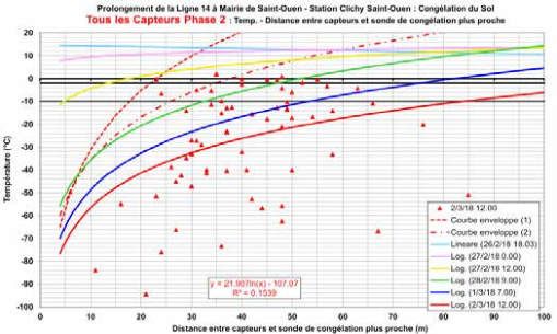
CHANTIER
Derniers projets de congélation de sol (liste non
exhaustive):
Les derniers projets de congélation réalisés en
France sont les suivants :
Paris, A86 - Socatop (niches de sécurité- 2006-
VCGP- Spie fondations),
Vaujours (Intrafor/ Cofor puits d’accès - 1985),
Lyon, BPLN (Lyon, rameau de connexion- GTM/
Bouygues - 1996),
Paris, ligne 14 station porte de Clichy, rameau de
liaison avec le TGI (2016, entreprises ICOP/ Eiffage
Figure 1 : Vue 3D de la station Clichy-Saint-Ouen - 3D view of the Clichy-Saint-
fondations)
Ouen station
Paris, ligne 12 (jonction tunnel/ parois moulées de
station/ Vinci construction, 2017)
Quantités principales
Paris, ligne 16, plot d’essai à Aulnay Sous-bois
Montant du marché de base : 60 074 326,17 € HT
(2017, Soletanche Bachy).
Période des travaux : de décembre 2014 à novembre 2019
Et en Europe :
Paroi moulée : 25 000m3
Italie, métro de Rome, ligne C station Sant Giovanni
Béton de structure : 30 000 m3
(Entreprise Trevi-2016)
Armatures : 6 000 t
Italie, métro de Naples, Ligne 6, Station Municipio
Paroi au coulis : 7 500 m²
(Entreprise Trevi – 2017)
Jet Grouting : 950 colonnes soit 11800 ml de forage et 4700 ml « jetés »
Italie, métro de Naples, ligne 6, 2 rameaux (2018,
Forages de congélation : 145 forages/ 1900 ml en cumulé
entreprise Maltauro)
Soutènement du tunnel : 300t en HEM 220
Italie, Tunnel de base du Brenner (en cours, 4 tunnels
à congeler de 35 m de longueur- Salini- Strabag)
Egypte, sous le canal de Suez, tunnel by pass Main quantities
(entreprise Bauer/ Deilmann Haniel) Base contract amount: 60,074,326.17 euros excl. VAT
Varsovie (Pologne), Ligne 2 station Centrum Nauki Period of works: from December 2014 to November 2019
Kopernik, entreprise Rodio Spezialtiefbau GmbH. Diaphragm wall: 25,000m3
Concrete structure: 30,000 m3
Reinforcement: 6,000 t
3. Présentation du lot T03 Grout wall: 7,500 m²
Jet Grouting: 950 columns or 11800 lm of drilling and 4700 lm “cast”
Le lot T03 consiste à créer la station Clichy Saint-Ouen, Freezing drilling: 145 boreholes/1900 lm cumulative
interconnectée avec la gare du RER C « Saint-Ouen ». Retaining the tunnel: 300t in HEM 220
Ce lot est initialement attaché au lot T02. Il a finalement
été séparé pour des raisons techniques, à savoir : 3.1. Contexte hydrogéologique
• Desdéviationslourdesderéseauxensurface(Gaz,
CPCU, eau, assainissement, électricité, fibres Les horizons rencontrés sont :
optiques, etc.), • Lesalluvionsmodernesetanciennes,
• Un passage sous le RER C qui présentait une • Les marno-calcaires de Saint-Ouen (MCSO) dont
méthode de pré-soutènement et d’étanchéité les calcaires de Ducy (CDU) à leur base,
unique : la congélation de sol. • Les sables de Beauchamp (SB) et les marnes
et caillasses (MC), avec un pendage NO->SE de
La station Clichy Saint-Ouen se compose des 6 l’ordre de 5% dans la zone traversée.
ouvrages suivants :
• Le corps de station (CSO), aux dimensions Le massif est baigné par 2 nappes : la nappe lutétienne
suivantes 140m x 15 m x 20 m de profondeur, alimentée par les MC et la nappe bartonienne par les
• Labaied’aérationmécanisée(BAM),20mx20mx20m, MCSO. Ces deux nappes sont séparées par le sable
• L’accèsprincipal(ACP), de Beauchamp médian, plutôt argileux et qui présente
• L’accèssecondaire(ACS), une perméabilité de 10-6 m/s.
• L’accèsSanzillon(ACZ),
• L’ouvrage cadre sous le RER C (OC) qui est un 3.2. Description de l’ouvrage cadre sous le RER C
tunnel de 26 ml de long, avec comme gabarit libre et fondations du RER C existantes
intérieur 9 m x 4 m.
L’ouvrage cadre « Ligne 14 » sous le RER C se trouve
En phase travaux, CSO sert de puits de sortie du tunnelier dans le gabarit des fondations du RER C. Construite
du lot T1, et la BAM de puits de sortie du lot T2. en 1987, la gare de Saint-Ouen est fondée sur des
barrettes, parois moulées et parois berlinoises. C’est
Il est à noter que l’accès principal, à l’est, permet à cause de ces fondations que le tunnelier du lot 2
l’interconnexion avec le RER C et que l’accès secondaire, n’a pu percer dans CSO. Le tunnel de jonction entre
à l’ouest permet le raccordement avec la ville de Clichy CSO et BAM doit donc être réalisé en creusement
et donc le département des Hauts de seine (92). « traditionnel ».
116 TUNNELS ET ESPACE SOUTERRAIN - N° 269 - Juillet/Août/Septembre 2019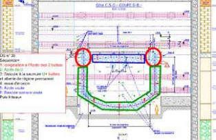
WORKSITES
3. Presentation of lot T03 The rock mass is covered by two water tables: the
Lutetian water table fed by the MC and the Bartonian
Lot T03 consists of creating the station Clichy Saint- water table by the MCSO. These two water tables are
Ouen, interconnected with the RER C station “Saint- separated by the medium Beauchamp sand, rather
Ouen”. clayey and which has a permeability of 10-6 m/s.
This lot was initially attached to lot T02. It was finally 3.2. Description of the framework structure under
separated for technical reasons, namely: RER C and existing RER foundations
• Heavydeviationsofsurfacenetworks(gas,CPCU,
water, sanitation, electricity, fibre optics, etc.), The framework structure “Line 14” under RER C is found
• ApassageunderRERCwhichpresentedaunique in the clearance of the RER C foundations. Built in 1987,
pre-retaining and sealing method: ground freezing. the Saint-Ouen station is based on bars, diaphragm walls
and Berlin walls. It is because of these foundations that
The station Clichy Saint-Ouen consists of the following the TBM of lot 2 could not break through the CSO. The
6 structures: junction tunnel between CSO and BAM must therefore
• The station body (CSO), with dimensions 140m x be done in “traditional” excavation.
15m x 20m deep,
The dimensions of the framework structure under
• The mechanised ventilation bay (BAM), 20m x
RER C are 26m x 13m x 8m.
20m x 20m,
• PrincipalAccess(ACP), Of the 3 bars encountered during the excavation, only
• SecondaryAccess(ACS), bar B3 is preserved, bar B12 is trimmed to be included
• SanzillonAccess(ACZ), in the side wall of the future civil engineering of the
• The framework structure under RER C (OC) structure and bar B11 is cut. A load transfer is carried
which is a tunnel 26 lm long, with as free internal out between bar B11 and the framework structure by
clearance of 9m x 4m. assembly (hyperstatic connection), via a support beam.
During the construction phase, CSO serves as the exit The excavated earths are mainly the Beauchamp sands
shaft for the T1 lot TBM, and the BAM for the T2 lot and the marly limestone of Saint-Ouen in vault, under
exit shafts. 15 metres of water, from where the need to freeze the
surrounding ground arose. The expected water flows in
It should be noted that the principal access, to the east, case of water inflow could be considerable and cause a
allows interconnection with the RER C and that the total flooding of line 14, up to Olympiades, which is why
secondary access to the west allows for a connection the project is classified as having a high technical risk.
with the town of Clichy and therefore the department of
It should be noted that the marly limestone of Saint-
Hauts de Seine (92).
Ouen was previously injected with a cement bentonite
slurry at 2 bar, with grouting lances.
3.1. Hydrogeological context
On the sands of Beauchamp, injectability tests with cement
The horizons encountered are: bentonite slurry, then microcement were carried out in the
• Modernandancientalluvialdeposits, experimental phase in 2013 but poor residual permeability
• The marly limestone of Saint-Ouen (MCSO) results led to the solution of ground freezing. A treatment of
including the Ducy limestones (CDU) at their base, the Beauchamp sands by horizontal jet grouting had also
• The sands of Beauchamp (SB) and marls and been approached in the pre-project studies phase, but
pebbles (MC), with a NW -> SE dip of about 5% in the approximate result of this method, in the face of the
the area crossed. induced risk, finally eliminated this solution.
Figure 2 : Vue en plan de l’ouvrage cadre sous le RER C - Plan view of the framework structure under RER C
TUNNELS ET ESPACE SOUTERRAIN - N° 269 - Juillet/Août/Septembre 2019 117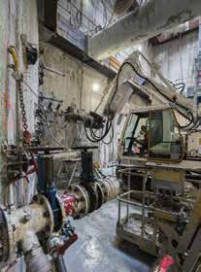
CHANTIER
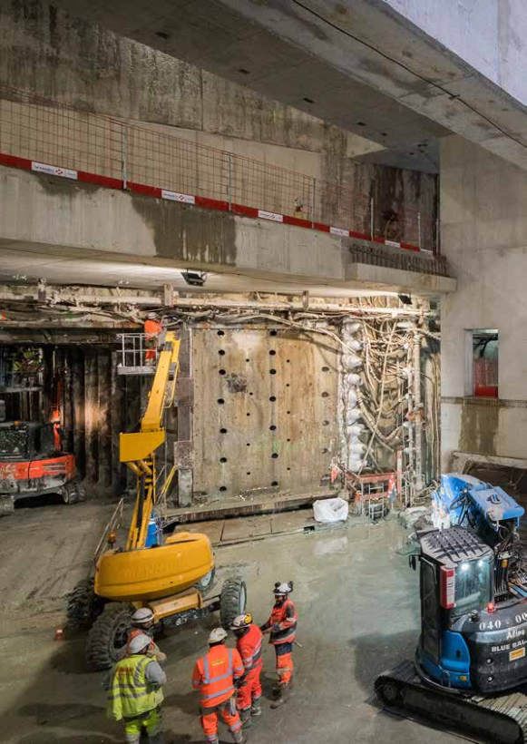
Figure 3 - 4 : Vue panoramique du tunnel excavé sous le RER C, avec la barrette B11 au centre - Panoramic view of
the tunnel excavated under RER C, with the B11 bar in the centre
Les dimensions de l’ouvrage cadre sous RER C sont 26 Le début du creusement s’est fait le 17 septembre
m x 13 m x 8 m. 2018, pour se finir le 9 mars 2019. Ces travaux ont été
exécutés en 3x8h, et 7j/7 afin de garantir une continuité
Des 3 barrettes rencontrées lors de l’excavation, seule la des travaux mais aussi une surveillance de l’ouvrage.
barrette B3 est conservée, la barrette B12 est rognée pour
être incluse dans le piédroit du futur génie civil de l’ouvrage Les principaux matériels spécifiques utilisés ont été les
et la barrette B11 est coupée. Un transfert de charge suivants :
est effectué entre la barrette B11 et l’ouvrage cadre par • 2 pelles tunnels (Wimmer blue badger et hitachi
moisage (liaison hyperstatique), via une poutre de reprise. PC 135) équipées de toute la panoplie spécifique
aux travaux souterrains (BRH, fraise et pinces à
Les terrains excavés sont principalement les sables
cintres) + 1 pelle wimmer blue badger en spare,
de Beauchamp et les marno-calcaires de Saint-Ouen
• 2 pelles brokk 330 et 500 pour les zones les plus exiguës,
en voûte, sous 15 mètres d’eau, d’où la nécessité de
• 4 robots béton projeté, 2 trémies à déblais, 4
congeler le terrain autour. Les débits d’eau attendus en
chargeurs.
cas de venues d’eau pourraient être considérables et
entrainer une inondation totale de la ligne 14, jusqu’à
L’expertise des services matériel des entreprises du
Olympiades, c’est pour cela que le projet est classé à
groupement, en particulier Sotrabas a été mise à profit
haut risque technique.
du projet afin d’avoir le matériel le plus adapté aux
Il est à noter que les marno-calcaires de Saint-Ouen ont contraintes de site (exiguïté, humidité etc ).
préalablement été injectés par un coulis de bentonite
ciment à 2 bars, sous tubes à manchettes.
A propos des sables de Beauchamp, des essais
d’injectabilité au coulis de bentonite ciment, puis
microciment ont été réalisés en phase expérimentale
en 2013 mais les résultats de perméabilité résiduelle
médiocres ont amenés à une solution par congélation
de sol. Un traitement des sables de Beauchamp par jet
grouting horizontal avait aussi été abordé en phase AVP
mais le résultat approximatif de cette méthode, face au
risque induit a finalement écarté cette solution.
Figure 5 : Réalisation d’une auréole de boulons forepoling au mini pantofore -
4. Les travaux souterrains Construction of a forepoling bolts halo with mini pantofore
La section du tunnel sous RER C à creuser est de 12 m
x 8 m fini, avec un biais de 30° par rapport à son axe.
Le tunnel est creusé en 6 sections différentes : 3 en
haut et 3 en bas. Les galeries du bas, ainsi que leur
génie civil sont d’abord réalisées afin d’assurer la
stabilité à la poussée d’Archimède.
Les galeries du haut sont faites dans un second temps,
puis leur GC et en particulier la liaison entre l’ouvrage
cadre et le RER C (réalisation d’une poutre en sous
œuvre et reprise des efforts par vérinage).
Le soutènement mis en place est fait de cadre en
HEM 220, et 30 cm de béton projeté fibré. Un soin
tout particulier est fait au niveau des assemblages
boulonnés car les cintres des galeries supérieures se Figure 6 : Une des équipes de creusement traditionnel lors du baptême du matériel
raccordent aux cintres du bas. - One of the traditional excavation teams at the baptism of the equipment
118 TUNNELS ET ESPACE SOUTERRAIN - N° 269 - Juillet/Août/Septembre 2019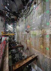
WORKSITES
Figure 7 : Coupe longitudinale de l’ouvrage cadre sous RER C - Longitudinal section of the framework structure under RER C
4. Underground works The upper tunnels are done in a second stage, then
their civil engineering works and in particular the
The section of tunnel under RER C to excavate is 12m connection between the framework structure and the
x 8m finished, with a bias of 30° to its shaft. RER C (construction of a beam under construction and
support effort through jacking).
The tunnel is excavated in 6 different sections: 3 at the
top and 3 at the bottom. The tunnels below, as well The support put in place is made of framework in HEM
as their civil engineering are first carried out to ensure 220, and 30cm of fibre-reinforced shotcrete. Particular
stability through Archimedes buoyancy. care is taken in the bolted joints because the arches of
the upper tunnels are connected to the lower arches.
The excavation start was on September 17th, 2018, to
end on March 9th, 2019. This work was done in 3 x 8
hour shifts, and 7 days a week, to ensure continuity of
the works but also a monitoring of the structure.
The main specific materials used were:
• 2 tunnel excavators (Wimmer Blue Badger and
Hitachi PC 135) equipped with all the equipment
specific to underground work (pneumatic drill,
cutter and arch grippers) + 1 Wimmer Blue Badger
excavator as spare,
• 2 Brokk 330 and 500 excavators for the smallest
areas,
• 4shotcreterobots,2cuttingshoppers,4crawlers.
Figure 8 : Début du creusement de la galerie G1, côté BAM - Start of the excavation
The expertise of the equipment departments of the
of the G1 gallery, BAM side
pool’s companies, in particular Sotrabas, was put to
use for the project in order to have the equipment best
suited to the constraints of the site (small size, humidity
etc.).
5. Ground freezing works
5.1. Principle:
The principle of ground freezing is to transform the
interstitial water (free water) from the ground into
ice (solid phase), thus ensuring a tight and resistant
connection between the grains of the ground. The
mechanical characteristics of the ground improve
because the ice plays the role of binder, decreasing at
the same time the permeability of the ground.
Figure 9 : Etat de la paroi moulée avant creusement - State of the diaphragm wall
before excavation
TUNNELS ET ESPACE SOUTERRAIN - N° 269 - Juillet/Août/Septembre 2019 119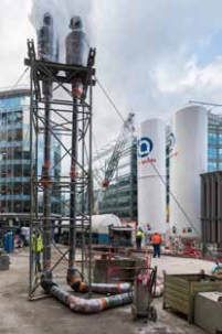
CHANTIER
5. Les travaux de congélation de sol
5.1. Le principe :
Le principe de la congélation des sols est de transformer
l’eau interstitielle (eau libre) du sol en glace (phase
solide), assurant ainsi une liaison étanche et résistante
entre les grains du terrain. Les caractéristiques
mécaniques du terrain augmentent car la glace joue
le rôle de liant, diminuant par la même occasion la
perméabilité du terrain.
La congélation d’un sol provient du transfert de
frigories d’un fluide à basse température vers le terrain
par l’intermédiaire d’une sonde : l’eau en contact avec
la sonde se transforme en glace formant une colonne
de terrain congelé, s’épaississant avec le temps, ce qui Figure 10 : Schéma de circulation type dans une sonde de congélation - Typical
permet de réaliser des murs étanches et résistants. flow diagram in a freezing probe
Ainsi, le comportement du sol est amélioré depuis la
période de mise en froid, pendant le maintien du froid
et ce jusqu’au dégel.
La solidification de l’eau interstitielle dans le terrain
donne au sol congelé une cohésion importante. En
effet, lors de la congélation, les contraintes appliquées
dans le terrain se répartissent à la fois sur le squelette
du sol et sur la glace formée lors de la mise en froid.
L’angle de frottement interne pour un sol congelé est
généralement considéré comme égal ou légèrement
inférieur à celui du sol non congelé.
De la même façon que la glace voit sa résistance
augmenter à mesure que la température baisse,
la résistance d’un terrain congelé dépend de la
Figure 11 : Schéma de principe installation de congélation à l’azote
température à laquelle il se trouve. A titre d’exemple,
une argile silteuse à -18°C présente une résistance Les températures minimales obtenues sont -196°c
en compression plus de 4 fois supérieure au même pour l’azote liquide et -36 °c pour la saumure.
matériau soumis à une température de -5°C, alors que
la glace verra sa résistance en compression augmenter Le process s’articule autour des 3 composantes
d’environ 35% seulement. Le graphique figure 12 principales suivantes :
synthétise les résultats des travaux de l’USAF (1960), • Leforage(précision/étanchéité),
de Wolfe & Thieme (1963) et Sayles (1965). • Lamiseenfroidetsonentretien(moyensmatériels
et humains),
La glace et donc les sols gelées sont des matériaux qui • La partie « ingénierie » (pilotage, auscultation,
fluent très rapidement. Lors des premières 24h sous R&D, impacts sur les existants, coupe Plaxis…,
charge, la résistance diminue fortement. gestion des risques etc).
Ces phénomènes ont été pris en compte dans Le projet de base conçu par la maîtrise d’œuvre prévoit
l’établissement du modèle mécanique qui a permis de un traitement par injection de coulis de ciment des
justifier la compatibilité des efforts apportés à la coque marno-calcaires de Saint-Ouen, et des marnes et
avec la résistance des Sables de Beauchamp congelés. caillasses ainsi qu’une congélation de sol des sables
de Beauchamp, par deux voiles congelés.
Le procédé utilisé sur la ligne 14 lot T03 est une
congélation mixte, à savoir : Le risque principal induit par la congélation est un
• Unecongélationprimaireàl’azoteliquide(miseen soulèvement du RER C situé au-dessus. Le gonflement
froid) pour figer rapidement l’eau des terrains, cryogénique est dû au changement d’état de l’eau dans
• Unentretiendelacongélationàlasaumure,pendant la matrice granulaire. D’une part, l’eau interstitielle
toute la durée du creusement du tunnel sous RER C. voit son volume augmenter de l’ordre de 10% lors du
changement d’état.
La congélation à l’azote liquide permet de « fixer »
l’eau dans les sols en cas de circulation dans l’aquifère
et de gagner du temps pendant la mise en froid. La
saumure permet un entretien « économique » de la
coque congelée à des températures plus élevées.
120 TUNNELS ET ESPACE SOUTERRAIN - N° 269 - Juillet/Août/Septembre 2019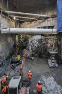
WORKSITES
The freezing of ground comes from the transfer of Liquid nitrogen freezing is used to “set” the water in
frigories from a fluid at low temperature to the ground the ground in the event of circulation in the aquifer
via a probe: the water in contact with the probe is and to save time during cold setting. Brine allows
transformed into ice forming a column of frozen ground, “economical” maintenance of the frozen shell at higher
thickening over time, which allows for waterproof and temperatures.
resistant walls. Thus, the behaviour of the ground is
improved from the cold period, over the maintenance The minimum temperatures obtained are -196°C for
of the cold and until thaw. liquid nitrogen and -36°C for brine.
The solidification of the interstitial water in the ground The process is organised around the following 3 main
gives the frozen ground significant cohesion. Indeed, components:
during freezing, the stresses applied in the ground • Drilling(precision/watertightness),
are distributed both over the skeleton of the ground • Cold setting and its maintenance (material and
and over the ice formed during the cold setting. The human resources),
internal friction angle for frozen ground is generally • The“engineering”part(supervision,surveys,R&D,
considered to be equal to or slightly lower than that of impacts on existing structures, Plaxis cutting..., risk
unfrozen ground. management, etc.).
In the same way that the ice increases in resistance as The basic project designed by the project management
the temperature drops, the resistance of frozen ground involves a cement slurry injection of the marly limestone
depends on the temperature at which it is situated. By of Saint-Ouen, and the marls and stones as well as a
way of example, a silty clay at -18°C has a compressive ground freezing of the Beauchamp sands, by two
strength more than 4 times greater than the same frozen runouts.
material subjected to a temperature of -5°C, whereas
ice will have a compressive strength increase of about The main risk from freezing is a heave of the RER C
only 35%. The following figure 12 summarises the above. The cryogenic swelling is due to the change of
results of the USAF (1960), Wolfe & Thieme (1963) state of the water in the granular matrix. On the one
and Sayles (1965). hand, the interstitial water volume increases by about
10% during the change of state.
Ice and therefore frozen ground are materials that flow
very quickly. During the first 24 hours under load, the This increase in volume can be absorbed by the ground
resistance decreases sharply. in several ways. On the one hand, if permeability allows
it, by the evacuation of the surrounding liquid water by
These phenomena were taken into account in the piston effect, on the other hand, if permeability does not
establishment of the mechanical model that justified allow it, by mobilising the stiffness of the granular matrix.
the compatibility of the forces on the shell with the In case of low permeability and rigid terrain, a granular
resistance of the frozen Beauchamp Sands. reorganisation takes place, leading to an increase in
volume. This increase is, however, limited to the fringe
The process used on line 14 lot T03 is mixed freezing, undergoing a change of state, there is no increase
namely: in volume when the change of state is completed.
• Aprimaryfreezingwithliquidnitrogen(coldsetting) Another phenomenon, cryogenic suction, can lead
to rapidly freeze water from the ground, to continuous increases over time. This phenomenon
• Maintenanceoffreezingwithbrine,throughoutthe concerns medium to low permeability grounds, such
entire tunnel excavation under RER C. as silts. At the microscopic level, free water freezes
at the melting temperature of water. Bound water, on
the other hand, freezes at lower temperatures due to
intermolecular energy near the grains. It remains liquid,
but at temperatures below its melting temperature, so
in an unstable state. The melting temperature of a
liquid is related to the pressure. So to compensate for
this unstable state, the bound water is in depression
and creates suction. The surrounding water in the non-
frozen portion is drawn to the frost line. This cryogenic
suction thus creates linear increases in volume over
time. This phenomenon is however less pronounced
at depth due to the surrounding pressure making it
possible to compensate for the instability of the free
water.
The “U” shape of the frozen shell also induces a
problem of buoyancy under Archimedes’ pressure,
during the excavation. The ballasting of the structure
was required and constituted a real difficulty in the
construction phasing (division of the excavation).
Figure 12 : UCS de quelques échantillons (sables, argiles, glace)
TUNNELS ET ESPACE SOUTERRAIN - N° 269 - Juillet/Août/Septembre 2019 121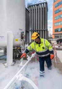
CHANTIER
Cette augmentation de volume peut être absorbée Malgré les dispositions prises, les forations sous environ
par le terrain de plusieurs façons. D’une part, si la 2 bars de pression de la nappe ont constitué une étape
perméabilité le permet, par l’évacuation de l’eau à risque pour le projet (risque de débourrage du sable
liquide environnante par effet piston, d’autre part, si la de Beauchamp).
perméabilité ne le permet pas, en mobilisant la raideur
de la matrice granulaire. En cas de perméabilité faible Des essais de trajectomètrie, par utilisation de visée
et de terrain de forte raideur, une réorganisation optique (théodolite et maxibor), puis de mesures
granulaire a lieu, menant à une augmentation de gyroscopiques ont permis de déceler d’éventuelles
volume. Cette augmentation est cependant limitée à fenêtres dans la coque qui ont ensuite nécessité des
la frange en cours de changement d’état, il n’y a plus fermetures par l’exécution de forages complémentaires,
d’augmentation de volume lorsque le changement du côté du front où se situe la fenêtre, ou alors depuis
d’état est terminé. Un autre phénomène, la succion le front symétrique.
cryogénique, peut mener à des augmentations
continues dans le temps. Ce phénomène concerne Au total 139 forages, 60 coté CSO, 56 coté BAM, et
les terrains de perméabilité moyenne à faible, tels que 23 forages d’auscultation ont été exécutés entre juin et
les limons. Au niveau microscopique, l’eau libre gèle novembre 2017.
à la température de fusion de l’eau. L’eau liée, quant
à elle, gèle à des températures plus faibles du fait de
l’énergie intermoléculaires à proximité des grains. Elle
reste donc liquide, mais à des températures inférieures
à sa température de fusion, donc dans un état instable.
La température de fusion d’un liquide est liée à la
pression. Ainsi pour compenser cet état instable, l’eau
liée est en dépression et crée de la succion. L’eau
environnante située dans la partie non-gelée est attirée
vers le front de gel. Cette succion cryogénique crée
donc des augmentations linéaires du volume dans le
temps. Ce phénomène est cependant moins prononcé
en profondeur car la pression environnante permet de
compenser l’instabilité de l’eau libre.
La forme en « U » de la coque congelée a également
induit une problématique de flottaison sous la poussée
d’Archimède, lors de l’excavation. Le lestage de
l’ouvrage a été nécessaire et a constitué une réelle
difficulté dans le phasage de réalisation (découpage
du creusement).
5.2. Les forages
La partie « forages de congélation » est une étape
cruciale au bon fonctionnement de la coque congelée.
Les points « avant », côté « paroi moulée » sont connus
précisément et la cible à atteindre est une cible de 40
cm de diamètre à 13 m de longueur, c’est-à-dire que la
tolérance d’exécution est de 1.5 %.
Vue d’ensemble atelier de forage de congélation -
Les forages ont été réalisés à l’aide d’une foreuse Overview of freezing drilling work area
développée par les équipes du groupement, et les
barres de forages utilisées ont les caractéristiques
suivantes : longueur de 1 ml, diamètre intérieur de
89 mm, épaisseur de 8 mm. Un soin particulier est 6. L’auscultation
donné sur la qualité des filetages des tubes et sur les
épaulements usinés. L’auscultation particulière à la congélation de sol mise
en place est la suivante :
Pour se prémunir d’éventuelles venues d’eau pendant • 2 théodolites robotisés avec 90 cibles en gare du
la foration, le groupement a fait usage de : RER C,
• Tricôneséquipésdeclapetanti-retourspécifiques, • 1théodoliteensurfaceavec250ciblessurlebâti,
• Unecheminéed’équilibrage, • 1capteurdevibrationengare,
• Deportesasscellésdanslaparoimoulée, • 23 sondes de 7 thermocouples soit 161
• Un dispositif de sas à étages (vannes guillotines thermocouples,
et dosapro), type « B.O.P », sans dispositif de • 116capteursdetempératureinstalléssurlestêtes
sectionnement de barre de forage. de congélation afin de connaître les températures
de retour dans chaque tube,
• 10piézomètresautomatisés.
122 TUNNELS ET ESPACE SOUTERRAIN - N° 269 - Juillet/Août/Septembre 2019WORKSITES
Trajectometry tests, using optical sighting (theodolite
and maxibor), followed by gyroscopic measurements
revealed possible windows in the shell, which then
required closures by performing additional drilling, on
the side of the front where there is the window, or from
the symmetrical front.
A total of 139 boreholes, 60 CSO side, 56 BAM side,
and 23 boreholes were completed between June and
November 2017.
Figure 13 : Vue en plan de la congélation - Plan view of freezing
Figure 14 : Plan de tir de la congélation, côté CSO - View of freezing, CSO side
5.2. Drilling Figure 15 : Atelier de forage de congélation avec SAS en
premier plan - Freezing drilling work area with air lock in
The “freezing drilling” part is a crucial step in the proper the foreground
functioning of the frozen shell. The “front” points on
the “diaphragm wall” side are precisely known and the 6. Surveys
target to be reached is a target 40 cm in diameter at 13
m in length, that is, the execution tolerance is 1.5%. The surveys specific to ground freezing are as follows:
• 2robotictheodoliteswith90targetsintheRERC
The drilling was carried out using a drill developed by station,
the teams of the group, and the drill bars used have • 1 theodolite on the surface with 250 targets over
the following characteristics: length of 1 lm, internal the construction,
diameter of 89 mm, thickness of 8 mm. Special care is • 1vibrationsensorinthestation,
given to the quality of the threads of the tubes and the • 23 probes with 7 thermocouples, i.e. 161
machined shoulders. thermocouples,
• 1 16 temperature sensors installed on the freezing
To prevent any water inflows during the drilling, the heads to display the return temperatures in each tube,
pool made use of: • 10automatedpiezometers.
• Triconesequippedwithspecificanti-returnvalve,
• Abalancingchimney, For the thermocouples, the objective is to measure
• Asealeddoorinthediaphragmwall, the temperature of the ground at a distance from the
• A multi-stage airlock (guillotine and dosapro axis of the freezing probes. The holes were therefore
valves), of type “BOP”, without drilling bar cut-off “azimuthed”, in the vertical part, and inclined, in the
device. horizontal parts of the shell. Once the 3D recording
was done, the distance of each thermocouple to the
In spite of the measures taken, the boring, under about freezing probes made it possible to extrapolate the
2 bars of pressure, of the groundwater constituted temperature in the shell using a logarithmic model of
a risky step for the project (risk of clearing the the distribution of temperatures in the ground (thermal
Beauchamp sands). response of ground - see point below).
TUNNELS ET ESPACE SOUTERRAIN - N° 269 - Juillet/Août/Septembre 2019 123CHANTIER
A propos des thermocouples, l’objectif est de mesurer
la température du sol à distance de l’axe des sondes
congélatrices. Les forages ont donc été azimutés,
dans la partie verticale, et inclinés, dans les parties
horizontales de la coque. Une fois réalisé le récolement RER C
en 3D, la distance de chaque thermocouple aux sondes
congélatrices a permis d’extrapoler la température
dans la coque grâce à un modèle logarithmique de
la distribution des températures dans le sol (réponse
thermique d’un sol- cf point ci-dessous).
CSO OUVRAGE
CADRE
Ce faisant, nous avons cherché à connaitre la réponse B9 B4
réelle des 3 faciès suivants:
• LecalcairedeDucyenpartiesupérieure,
• LessablesdeBeauchampenpartie«piédroit»,
• L es sables de Beauchamp en partie « contre-voute ».
Figure 16 : Vue 3D de la coque congelée - 3D view of the frozen shell
Le stockage des données issues des mesures
Les objectifs principaux du séquençage de la
d’auscultation du projet de congélation se fait au moyen congélation primaire sont donc de :
de bases de données. Les données sont ensuite traitées • Figer les circulations d’eau au niveau du calcaire
automatiquement (seuils d’alerte) et manuellement pour de Ducy de façon prioritaire,
piloter la coque congelée et optimiser son efficacité. • Puis vérifier la bonne tenue de la coque soumise
aux circulations naturelles de la nappe.
Les entreprises qui sont intervenues sur le projet pour
la partie « auscultations » sont notamment ITM sol, A l’issue du séquençage puis du test d’érosion, qui a
Soldata, Solexpert et Hydrophy (traçages hydrauliques). prouvé que la coque ne s’érodait pas, la congélation de
la voûte parapluie a pu se faire dès le 16 avril 2018. Il
6.1. Préalable à la congélation de sol est à noter que le test d’érosion a 2 objectifs :
• Vérifierquelacoquecongeléenes’érodepassuite
La reconnaissance des circulations des nappes à des circulations d’eaux souterraines,
phréatiques traversées par le projet a été une étape • Mais aussi vérifier que le terrain ne s’érode pas
essentielle au projet de congélation. Les deux nappes (augmentation de la perméabilité du sol suite à la
bartonienne et lutétienne sont initialement séparées constatation d’une augmentation de MES -Matières
par les sables de Beauchamp médians. en suspension- dans les eaux issues des drains).
Durant la phase « exécution », des circulations
verticales ont été décelées, celles-ci se justifient par
l’activité anthropique depuis plusieurs décennies :
des pompages industriels anciens dans la nappe du
lutétien, au niveau de la plaine de Saint-Denis mais
aussi sur la commune de Saint-Ouen ; ainsi que
la présence d’un bâti dense à proximité (RER C,
bâtiments de bureaux et habitats).
Des potentielles dissolutions de gypse y découlant ont
entrainé des effondrements locaux « métriques » ; ce
phénomène a d’ailleurs été découvert en station.
La base des calcaires de Saint-Ouen, caractérisée
par le calcaire de Ducy a été le lieu de circulations
importantes, amplifiées par les activités de forage
et l’effet barrage. En effet, la réalisation des parois
moulées de CSO et de BAM a créé un barrage artificiel
aux circulations souterraines naturelles, et a concentré
les circulations entre les deux puits, sous le RER C.
Afin de cartographier les circulations locales, le
groupement a procédé à un traçage des nappes par
l’utilisation de traceurs (éosine, uranine, fluorescéine)
injectés dans des drains ou des piézomètres. Les
résultats de cette cartographie (vitesse ponctuelle
maximale de 19 m/j) ont entrainé la réalisation d’un
séquençage de la congélation ainsi qu’à un test de Figure 17 : Front côté CSO avec vue sur la congélation
stabilité d’érosion thermique des piédroits congelés. - Front on CSO side with view on the freezing
124 TUNNELS ET ESPACE SOUTERRAIN - N° 269 - Juillet/Août/Septembre 2019WORKSITES
In doing so, we sought the true answer to the following activity over several decades: old industrial pumping in
3 facies: the Lutetian water table, at the level of the Saint-Denis
• TheDucylimestoneatthetoppart, plain but also in the commune of Saint-Ouen; as well
• ThesandsofBeauchampinthe“sidewall”part, as the presence of a dense building area nearby (RER
• ThesandsofBeauchampinthe“counter-vault”. C, office buildings and residential).
Storage of the data from the survey measurements of Potential dissolutions of gypsum resulting from this led
the freezing project is done by means of a database. to local “metric” collapses; this phenomenon has also
The data is then processed automatically (alert been discovered in the station.
thresholds) and manually to control the frozen shell
and optimise its efficiency. The limestone base of Saint-Ouen, characterised by
the Ducy limestone was the location of significant
The companies involved in the project for the “surveys” circulation, amplified by the drilling activities and the
part include ITM Sol, Soldata, Solexpert and Hydrophy dam effect. Indeed, the construction of the CSO and
(hydraulic tracings). BAM diaphragm walls created an artificial dam for the
natural underground circulation, and concentrated the
6.1. Prerequisites for ground freezing circulations between the two shafts, under RER C.
The surveying of water table circulation crossed by the In order to map the local circulations, the pool
project was an essential step in the freezing project. proceeded to trace the layers by the use of markers
The two Bartonian and Lutetian layers are initially (eosin, uranine, fluorescein) injected into drains or
separated by the median Beauchamp sands. piezometers. The results of this mapping (maximum
punctual velocity of 19m/d) led to the sequencing for
During the “execution” phase, vertical circulations the freezing as well as to a thermal erosion stability test
were detected, which have been caused by human of the frozen side walls.
Séquençage de la congélation - Sequencing of freezing
Plan de séquençage selon l’OS 35 - Sequencing plan as per OS 35
Dates effectives : Effective dates:
19 février 2018 : 1 (Azote sur haut piédroit) February 19, 2018: 1 (Nitrogen on upper sidewall)
24 février 2018 : 2 (Azote sur U) February 24, 2018: 2 (nitrogen on U)
26 Mars : 4 (Test érosion) March 26: 4 (Erosion test)
16 avril : 5 (Voute congelée) April 16: 5 (Frozen vault)
25 avril : fin de la congélation April 25: end of freezing
26 juin : Arrêt de la voute June 26: Stopping the vault
Juillet/ aout : études et OS July/August: studies and OS
17 Septembre : creusement September 17: excavation
11 décembre 2018 : fin creusement bas December 11, 2018: end lower excavation
1 février 2019 : début creusement haut February 1, 2019: start upper excavation
7 mars : fin creusement haut March 7th: end upper excavation
TUNNELS ET ESPACE SOUTERRAIN - N° 269 - Juillet/Août/Septembre 2019 125CHANTIER
Un silo d’azote a été conservé pendant toute la durée
du chantier afin de pouvoir « re-basculer » à l’azote
en cas de venue d’eau. Un groupe froid « saumure »
de secours, de même capacité que le groupe initial,
a été mis en place en cas de défaillance. Ce choix se
justifiait du fait de l’absence de retour d’expérience sur
des projets de congélation aussi longs (test à l’usure
du matériel).
7. Soulèvements du RER C et adapta-
tion de la congélation
Aucun seuil de soulèvement du RER C n’est prévu
au marché. Dans un premier temps, les seuils de
tassement ont été utilisés pour le soulèvement.
Le tassement admissible initial du RER C est de 5 mm ;
il a dû être réévalué au soulèvement à 40 mm au fil du
projet, suite notamment à une modélisation intégrale
de la gare existante.
En effet, dès la première phase de congélation le
19/02/2018, des soulèvements du RER C ont été
observés, montrant à la fois un phénomène de
gonflement cryogénique important (dû aux effets de
cryo-succion) mais aussi la présence de fondations
existantes du RER C « travaillant » au contact de la
congélation de sol.
Figure 18 : Cheminées d’évacuation d’azote - Nitrogen Afin de limiter ces soulèvements, les actions suivantes
evacuation chimneys ont été menées :
• Arrêtdecongélationdelavoûte,etadaptationdu
pré-soutènement (tôle de blindage) ;
La quantité d’azote liquide injectée lors de la première • Réchauffement de la voûte congelée par une
phase a été de 3500 m3, soit environ 1 m3 d’azote/m3 circulation de saumure à température ambiante ;
de terrain congelé. • RenforcementdesauscultationsdansleRER-C;
• Augmentation de la température de consigne de
Puis le maintien en froid s’est fait à l’aide d’un saumure ;
groupe froid à tour de refroidissement intégrée, d’une • Études de faisabilité de congélation mixte
puissance de 450 kW. « saumure/ saumure » ou « azote/ saumure ».
Figure 19 : Extrait du logiciel d’auscultation « geoscope»: soulèvements dès le début de la congélation et tassement à la décongélation. - Extract
from the “geoscope” survey software: heaving from the start of the freezing and settling during thawing.
126 TUNNELS ET ESPACE SOUTERRAIN - N° 269 - Juillet/Août/Septembre 2019WORKSITES
The main objectives of the sequencing for the primary 7. RER C heaving and freezing
freezing are therefore:
• FreezewatercirculationattheDucylimestonelevel adaptation
as a priority,
• Then check the proper behaviour of the shell No heave threshold of the RER C is set out in the
subjected to the natural circulation of the water contract. At first, settlement thresholds were used for
table. heaving.
After the sequencing and then the erosion test, which The initial allowable settlement of the RER C is 5 mm;
proved that the shell was not eroding, the freezing of it had to be re-evaluated to 40 mm during the project,
the umbrella vault could be done as early as 16 April following in particular a complete modelling of the
2018. It should be noted that the erosion test has two existing station.
objectives:
• C
heckthatthefrozenshelldoesnoterodedueto Indeed, from the first freezing phase on 19/02/2018,
groundwater circulation, RER C heaves were observed, showing both a
phenomenon of significant cryogenic swelling (due to
• A
ndalsotoverifythatthegrounddoesnoterode
cryo-suction effects) but also the presence of existing
(increase of ground permeability following the
RER C foundations “working” in contact with ground
observation of an increase of SS (suspended solids)
freezing.
in the waters coming from the drains).
In order to limit these heaves, the following actions
were carried out:
• Stop of vault freezing, and adaptation of the pre-
support (armouring sheet);
• Re-heatingofthefrozenvaultbyabrinecirculation
at room temperature;
• ReinforcementofsurveysintheRER-C;
• Increasingthebrinesettemperature;
• Feasibilitystudiesofmixedbrine/brineornitrogen/
brine.
The increase in the brine’s set temperature, making it
possible to be sufficiently safe with respect to the risk
of water inflow, and limiting the RER C heave, finally
constituted the driving and limiting point of the project.
Indeed, the initial set temperature of -36°C had to be
raised to -28°C to stop heaving. Unfortunately, the
temperature of -28°C was insufficient as tunnel excavation
progressed. A sensor, identified as critical because it is
located in the Ducy limestone, in a high flow zone and
close to the heat source represented by the BAM shaft,
reached the threshold threshold temperature.
The pool had to quickly lower this setpoint temperature
to -34°C.
This temperature could not be reached for the following
Figure 20 : Remplissage silo d’azote - Filling nitrogen silo
reasons:
The quantity of liquid nitrogen injected during the • Heat exchange (contact between frozen ground/
first phase was 3500m3, i.e. approximately 1m3 of excavation with presence of excavation machine)
nitrogen/m3 of frozen ground. became too significant,
• Wearoffreezingequipmentinducingalossofyield.
Then the cold maintenance was done with the help of a
cooling unit with integrated cooling tower, with a power Mixed freezing “nitrogen/brine” was therefore made
of 450kW. necessary later (cf § Mixed freezing).
A nitrogen silo was stored throughout the construction All of these phenomena are the consequence of
site to be able to “switch back” to nitrogen in case of freezing in a mixed front in plan view, but also in
water inflow. A cold “brine” backup unit, with the same altimetry. The pool therefore adapted to carry out a
capacity as the initial unit, was set up in case of failure. “selective” freezing depending on the reaction of the
This choice was justified by the lack of feedback on ground, associated RER C heaves, but also based
similar long freezing projects (equipment wear tests on the progress of the excavation (increasing heat
etc.). exchange).
TUNNELS ET ESPACE SOUTERRAIN - N° 269 - Juillet/Août/Septembre 2019 127Vous pouvez aussi lire