User Manual Model HCS - A division of Enphase Energy, Inc.
←
→
Transcription du contenu de la page
Si votre navigateur ne rend pas la page correctement, lisez s'il vous plaît le contenu de la page ci-dessous
A division of Enphase Energy, Inc.

    User Manual
•   •    • • • •              •
        Model HCS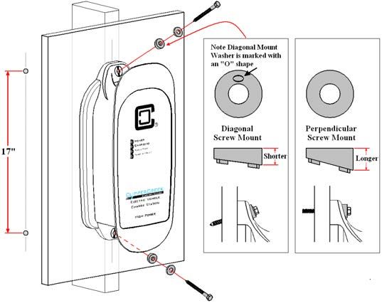
HCS User Manual
PLEASE NOTE
This user manual includes the latest information at the time of
printing. Enphase Energy, Inc. reserves the right to make changes
to this product without further notice. Changes or modifications to
this product by other than an authorized service facility may void the
product warranty.

Contact a Customer Service Representative with any questions about
the use of this product. (877) 694-4194

                WARNING: This product can expose you
                to chemicals, including Carbon Black, which
                is known to the State of California to cause
                cancer. For more information go to:
                www.P65Warnings.ca.gov

                AVERTISSEMENT: Ce produit peut vous
                exposer à des agents chimiques, y compris
                Noir Carbone, identifiés par l’État de
                Californie comme pouvant causer le cancer.
                Pour de plus amples informations, prière de
                consulter: www.P65Warnings.ca.gov

                ADVERTENCIA: Este producto puede
                exponerte a químicos, incluso Negro
                Carbón, que se conocido por el Estado de
                California como causante de cáncer. Para
                más información visite:
                www.P65Warnings.ca.gov

To view the latest version of this manual please visit
clippercreek.com/installation-manuals

HCS User Manual, Version 21, April 2022
© 2022 Enphase Energy, Inc.
All rights reserved. Printed in the USA.

Manual Number: 7004-0014-B
                                           2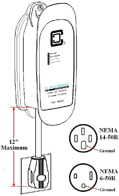
HCS User Manual
CONTENTS
IMPORTANT SAFETY INSTRUCTIONS................................................5
   Instructions Pertaining to a Risk of Fire or Electric Shock                                          6
   Additional Safety Instructions                                                                      12
FCC INFORMATION................................................................................14
OPERATION............................................................................................... 15
   The HCS Front Panel                                                                                 16
INSTALLATION - SERVICE CONNECTIONS..................................... 17
MOUNTING PROCEDURES................................................................... 25
   HCS EVSE Mounting for Hollow-Wall Construction                                                      26
   HCS EVSE Mounting for Solid-Wall Construction                                                       27
MOUNTING THE SAE J1772 CONNECTOR HOLSTER....................28
CHARGE CABLE WRAP GUIDELINES...............................................30
WIRING INSTRUCTIONS (Hardwired HCS)....................................... 31
RECEPTACLE INSTRUCTIONS (Plug-In HCS).................................. 33
GROUNDING INSTRUCTIONS.............................................................. 34
   HCS Hardwired EVSE Grounding                                                                        34
   HCS Plug-In EVSE Grounding                                                                          34
USING THE PADLOCK............................................................................35
MOVING & STORAGE INSTRUCTIONS.............................................36
OPTIONAL FEATURES...........................................................................37
MAINTENANCE ....................................................................................... 38
CUSTOMER SUPPORT............................................................................39
SPECIFICATIONS..................................................................................... 40
WARRANTY INFORMATION (3 Year Standard).................................42
WARRANTY INFORMATION (5 Year Ruggedized).............................43

                                                         3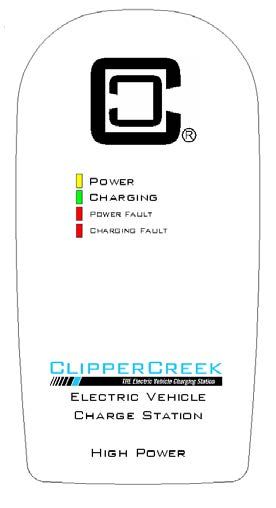
HCS User Manual
ILLUSTRATIONS
Figures
1.    HCS Front Panel.............................................................................................16
2.    220/240V Single Phase..................................................................................21
3.    208V 3-Phase, Wye-Connected......................................................................21
4.    240V 3-Phase, Delta-Connected, with Center-Tap on One Leg....................22
5.    Mounting the HCS to a Hollow-Wall.............................................................26
6.    Mounting the HCS to a Solid-Wall................................................................27
7.    Mounting the SAE J1772 Connector Holster Using the Exterior
      Wood Screws and Washers.............................................................................29
8.    Drape the Charge Cable Loosely Around the HCS Enclosure.......................30
9.    Wiring the HCS in a Junction Box.................................................................31
10.   Preferred Orientation of the NEMA Receptacles Below the Plug-in HCS....33
11.   Locking the SAE J1772 Connector with Padlock Included...........................35
12.   Charge Connector Secured with Padlock which Cannot be Removed
      from Vehicle without Key..............................................................................35
13.   Padlock Used in Combination with Connector Holster After Charging........35
14.   HCS Enclosure Dimensions...........................................................................41

Tables
1.    Front Panel LED Information........................................................................16
2.    Service Connections for Standard & Ruggedized HCS.................................17

                                                             4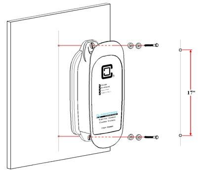
HCS User Manual
IMPORTANT SAFETY INSTRUCTIONS
Carefully read these instructions and the charging instructions in
your vehicle owner’s handbook before charging your electric vehicle.
The following symbols may be found in this manual or on labels
affixed to the Electric Vehicle Supply Equipment (EVSE):
       NOTE: This means pay particular attention. Notes contain
       helpful suggestions.
       REMARQUE: Cela signifie accorder une attention
       particulière. Les remarques contiennent des suggestions
       utiles.
       NOTA: Esto significa que debe prestar especial atención.
       Las notas contienen sugerencias útiles.
       CAUTION: This symbol means be careful. There is
       potential to do something that may result in damage to the
       equipment.
       ATTENTION: Ce symbole signifie être prudent. Vous
       êtes capable de faire quelque chose qui pourrait causer des
       dommages à l’équipement.
       ATENCIÓN: Este símbolo significa tener cuidado. Usted
       es capaz de hacer algo que puede resultar en daños al
       equipo.
       WARNING: This symbol means danger. You are in a
       situation that could cause bodily injury. Before you work
       on any electrical equipment, be aware of the hazards
       involved with electrical circuitry and standard practices for
       preventing accidents.
       AVERTISSEMENT: Ce symbole signifie un danger.
       Vous êtes dans une situation qui pourrait causer des
       blessures corporelles. Avant de travailler sur un équipement
       électrique, être conscient des dangers présentés par les
       circuits électriques et les pratiques courantes de prévention
       des accidents.
                                  5
HCS User Manual
ADVERTENCIA: Este símbolo significa peligro. Está en
una situación que podría lesionarse. Antes de trabajar en
cualquier equipo eléctrico, debe estar consciente de los
riesgos relacionados con los circuitos eléctricos y practicas
estándares de prevención de accidentes.
Instructions Pertaining to a Risk of Fire or Electric Shock
When using the HCS, basic electrical safety precautions should be
followed:
• Use this EVSE to charge electric vehicles equipped with an
SAE J1772 charge port only. Consult the vehicle’s owner
manual to determine if the vehicle is equipped with the
correct charge port.
• Make certain the EVSE SAE J1772 charge cable is
positioned so it will not be stepped on, tripped over, or
otherwise subjected to damage or stress.
• This product contains no user serviceable parts. Consult
the Customer Support section in this manual for service
information. Do not attempt to repair or service the EVSE
yourself.
• Do not operate your EVSE if it or the SAE J1772 charge
cable is physically open, cracked, frayed, or otherwise
visibly damaged. Contact a Service Representative for
service immediately. Consult the Customer Support
section in this manual for information on the Service
Representative in your area.
• Not for use in commercial garages where a
COMMERCIAL GARAGE is defined as a facility (or
portion thereof) used for the repair of internal combustion
vehicles in which the area may be classified due to
flammable vapors being present (such as from gasoline).
6HCS User Manual
• Do not place fingers inside of the coupler end of the
SAE J1772 charge cable.
• Do not allow children to operate this device. Adult
supervision is mandatory when children are in proximity to
an EVSE that is in use.
Additional Instructions for Plug-In HCS Configurations
• 240V plugs are specifically designed for occasional
relocation, such as moving from one home to another home.
• For personal safety, the circuit breaker MUST be turned off
prior to plugging in AND/OR unplugging 240V appliances
(including this EVSE).
• A dedicated NEMA outlet (receptacle) is highly
recommended. NEMA outlets wear out over time
particularly when repeated insertion and removal of NEMA
plugs occur. Check the receptacle to be sure it is not worn. A
worn receptacle can cause the plug connection to overheat
and become a fire hazard. Do not use a plug that gets
excessively hot. It is recommended that plug-in EVSE
remain plugged in.
• Have an electrician verify all wiring to the outlet is correct
and in compliance with local code requirements before
connecting the EVSE.
• Do Not use this EVSE with an extension cord or wall plug
adapter. Plug this EVSE directly into the receptacle.
• Ensure that the EVSE is mounted to the wall or placed on a
support so it does not hang from the receptacle. Receptacles
are not designed to support the weight of the EVSE.
7HCS User Manual
Instructions se Rapportant à un Risque d’Incendie ou de
Choc Électrique
Lorsque l’utilisation de la HCS, précautions fondamentale de
sécurité électrique doivent être suivies:
• Utilisez cette station de recharge pour charger les véhicules
électriques équipés d’un SAE J1772 port de recharge
seulement. Consultez le manuel du propriétaire du véhicule
afin de déterminer si le véhicule est équipé d’un correcte
port de recharge.
• Assurez-vous que le SAE J1772 câble de recharge sur la
station de recharge est positionné de telle sorte qu’il ne sera
pas piétiné, accroché plus de, ou autrement endommagé ou
de subir le stress.
• Ce produit ne contient aucune pièce réparable par
l’utilisateur. Consultez la section Support à la Clientèle
dans ce manuel pour obtenir des informations de service.
N’essayez pas de réparer ou d’entretenir la station de
recharge vous-même.
• Ne faites pas fonctionner votre station ou le câble de
recharge si elles sont physiquement ouverte, fissuré,
effiloché, ou autrement visiblement endommagé. Contactez
votre représentant du service pour service immédiatement.
Consultez la section Support à la clientèle dans ce manuel
pour obtenir des informations sur le représentant du service
dans votre région.
• Ne pas utiliser dans les garages commerciaux où un garage
commercial est défini comme une installation (ou une
partie) utilisé pour la réparation de véhicules à combustion
interne dans lequel la zone peut être classée en raison
de vapeurs inflammables étant présents (Tels que de
l’essence.)
• Ne posez pas les doigts à l’intérieur de l’extrémité du
SAE J1772 coupleur du câble de recharge.
8HCS User Manual
• Ne pas laisser les enfants utiliser cet appareil. Supervision
d’un adulte est obligatoire lorsque des enfants sont à
proximité d’une station de recharge qui est en cours
d’utilisation.
Instructions supplémentaires pour les configurations HCS
enfichables
• Les prises de 240V sont spécialement conçues pour les
relocalisations occasionnelles, tel que le déménagement
d’une maison à une autre.
• Pour des raisons de sécurité, le disjoncteur DOIT être
désactivé avant de brancher ET/OU débrancher les appareils
de 240V (dont cet EVSE).
• Une sortie (réceptacle) NEMA dédiée est fortement
recommandée. Les réceptacle NEMA s’usent avec le temps,
en particulier lorsque l’insertion et le retrait des prises NEMA
sont répétés. Vérifiez le réceptacle pour vous assurer qu’elle
n’est pas usée. Une réceptacle usée peut provoquer une
surchauffe du connecteur de raccordement et constituer un
risque d’incendie. Ne pas utiliser de prise qui deviendrait
excessivement chaude. Il est recommandé que la prise de
l’EVSE reste branchée.
• Faites vérifier par un électricien que tout le câblage de
réceptacle soit correctement effectué et conforme aux
exigences de la réglementation locale avant de raccorder
l’EVSE.
• Ne pas utiliser cet EVSE avec une rallonge ou adaptateur
de prise murale. Branchez cet EVSE directement dans le
réceptacle.
• S’assurer que l’EVSE est fixé au mur ou placé sur un
support afin qu’il ne soit pas suspendu à l’installation
électrique. Le réceptacle n’est pas conçue pour supporter le
poids de l’EVSE.
9HCS User Manual
Instrucciones relacionadas con un riesgo de incendio o
descarga eléctrica
Al utilizar el HCS, se deben seguir las siguientes precauciones
básicas de seguridad eléctrica:
• Utilice este EVSE para cargar vehículos eléctricos
equipados con un puerto de carga SAE J1772 únicamente.
Consulte el manual del propietario del vehículo para
determinar si el vehículo está equipado con el puerto de
carga correcto.
• Asegúrese de que el cable de carga del EVSE SAE J1772
esté colocado de manera que no sea pisado, ni cause
tropiezos, ni se someta a daños o tensiones.
• Este producto no contiene partes reparables por el usuario.
Consulte la sección de Atención al Cliente en este manual
para obtener información de servicio. No intente reparar o
reparar el EVSE usted mismo.
• No opere su EVSE si éste o el cable de carga SAE J1772
están físicamente abiertos, agrietados, deshilachados o
dañados de otra manera. Póngase en contacto con un
Representante de Servicio Técnico para su reparación.
Consulte la sección de Atención al Cliente en este manual
para obtener información sobre el Representante de
Servicio Técnico en su área.
• Este dispositivo no es para uso en garajes comerciales,
en el que un GARAJE COMERCIAL se define como
una instalación (o parte de la misma) utilizada para la
reparación de vehículos de combustión interna, en los
que el área puede ser clasificada debido a la presencia de
vapores inflamables (como los de la gasolina).
• No coloque los dedos dentro del extremo del acoplador del
cable de carga SAE J1772.
• No permita que los niños operen este dispositivo. La
supervisión de un adulto es obligatoria cuando haya niños
que estén cerca de un EVSE que está en uso.
10HCS User Manual
Instrucciones adicionales para configuraciones de HCS
enchufables
• Los tomacorrientes de 240V están específicamente
diseñados para reubicaciones ocasionales, como la
mudanza de una casa a otra.
• Por su seguridad personal, el interruptor de circuito
DEBE estar apagado antes de enchufar Y/O desenchufar
dispositivos de 240V (incluyendo este dispositivo EVSE).
• Se recomienda encarecidamente una salida (receptáculo)
NEMA dedicada. El receptáculo NEMA se desgastan con
el tiempo, especialmente cuando se produce una conexión y
desconexión repetidas de los enchufes NEMA. Verifique el
receptáculo para asegurarse de que no esté desgastada. Un
receptáculo desgastado puede causar que la conexión del
enchufe se sobrecaliente y sea riesgo de incendio. No use
un enchufe que se caliente demasiado. Se recomienda que
el EVSE enchufable permanezca enchufado.
• Haga que un electricista verifique que todo el cableado del
tomacorriente sea correcto y que cumpla con los requisitos
del código local antes de conectar el EVSE.
• No Use este EVSE con un cable de extensión o adaptador
de enchufe de pared. Conecte este EVSE directamente a la
toma el receptáculo.
• Asegúrese de que el EVSE esté montado en la pared
o colocado sobre un soporte para que no cuelgue del
receptáculo. Los enchufes no están diseñados para soportar
el peso del EVSE.
11HCS User Manual
Additional Safety Instructions
WARNING: Turn off power to the EVSE at the circuit
breaker panel before moving, servicing or cleaning the unit.
AVERTISSEMENT: Couper l’alimentation de l’EVSE au
niveau du panneau de disjoncteurs avant de déplacer,
d’effectuer la maintenance ou de nettoyer l’appareil.
ADVERTENCIA: Desconecte la alimentación del EVSE
en el panel del interruptor automático antes de mover,
reparar o limpiar la unidad.
WARNING: Always turn off input power to the EVSE
at the circuit breaker panel prior to plugging into or
unplugging from a wall socket.
AVERTISSEMENT: Toujours éteindre la puissance
d’entrée du EVSE sur le panneau du disjoncteur avant de
brancher ou de débrancher un socket mur.
ADVERTENCIA: Apague siempre la alimentación de
entrada al EVSE en el panel del interruptor de circuito,
antes de enchufarlo o desenchufarlo de un tomacorriente.
NOTE: VENTILATION - Some electric vehicles require
an external ventilation system to prevent the accumulation
of hazardous or explosive gases when charging indoors.
Consult the vehicle owner’s manual to determine if your
vehicle requires ventilation during indoor charging.
REMARQUE: VENTILATION - Certains véhicules
électriques nécessitent un système de ventilation externe
pour éviter l’accumulation de gaz explosifs ou dangereux
lors de la charge à l’intérieur. Consultez le manuel du
propriétaire du véhicule pour déterminer si votre véhicule
nécessite une ventilation quand le recharge en salle.
NOTA: VENTILACIÓN - Algunos vehículos eléctricos
requieren un sistema de ventilación externo para evitar
la acumulación de gases peligrosos o explosivos, al ser
12HCS User Manual
cargados en interiores. Consulte el manual del propietario del
vehículo para determinar si su vehículo requiere ventilación
durante la carga en interiores.
NOTE: Vehicles which conform to the SAE J1772
standard for communication can inform the charge station
that they require an exhaust fan. The HCS is not equipped
to control ventilation fans. Do not charge the vehicle with
the HCS if ventilation is required.
REMARQUE: Véhicules qui sont conformes à la norme
SAE J1772 de communication peuvent informer la station
de recharge qu’ils nécessitent un ventilateur d’extraction.
Le HCS n’est pas équipé pour contrôler les ventilateurs. Ne
chargez pas le véhicule avec les HCS si la ventilation est
nécessaire.
NOTA: Los vehículos que cumplan con el estándar de
comunicación SAE J1772 pueden informar que su EVSE
requieren un extractor de aire. El HCS no está equipado para
controlar ventiladores. No cargue el vehículo con el HCS si
se requiere ventilación.
CAUTION: DO NOT CHARGE a vehicle indoors if it
requires ventilation. Contact a Service Representative for
information.
ATTENTION: NE PAS RECHARGER un véhicule à
l’intérieur si il nécessite une ventilation. Contactez votre
représentant de service pour plus d’informations.
ATENCIÓN: NO RECARGUE un vehículo en interiores
si requiere ventilación. Póngase en contacto con su
Representante de Servicio Técnico para obtener más
información.
Save these instructions for future reference.
Conservez ces instructions pour référence future.
Guarde estas instrucciones para referencias futuras.
13HCS User Manual
FCC INFORMATION
This device complies with Part 15 of the FCC rules. Operation
is subject to the following two conditions: (1) This device may
not cause harmful interference, and (2) This device must accept
any interference received, including interference that may cause
undesired operation.
This product has been designed to protect against Radio Frequency
Interference (RFI). However, there are some instances where high
powered radio signals or nearby RF-producing equipment (such as
digital phones, RF communications equipment, etc.) could affect
operation.
If interference to the EVSE is suspected, the following steps
should be taken before consulting a ClipperCreek Sales or Service
Representative for assistance:
1. Reorient or relocate nearby electrical appliances or
equipment during charging.
2. Turn off nearby electrical appliances or equipment
during charging.
CAUTION: Changes or modifications to this product
by other than an authorized service facility may void
FCC compliance.
ATTENTION: Modifications apportées à ce produit par
qui conque autre qu’un centre de service autorisé peut
annuler la conformité FCC.
ATENCIÓN: Cambios o modificaciones a este product por
otros que no sean un centro de servicio autorizado pueden
anular el cumplimiento con la FCC.
14HCS User Manual
OPERATION
The HCS EVSE is a compact wall or pedestal-mounted EVSE
that provides the Plug-in Hybrid or Battery Electric Vehicle
(together Plug-In Electric Vehicles, or “PEV”) user with a safe
and manageable link between the power grid and the PEV. Both
hardwired HCS and plug-in HCS versions are available.
To use the HCS simply unwrap the charge cable and plug the SAE
J1772 connector firmly into the vehicle's charge port.
Normally, the vehicle will immediately request a charge using a
special communication line in the cable. Within a few seconds the
Green “Charging” light on the face of the HCS will turn on and the
charging cycle will begin. After an average driving day the vehicle
battery pack will require several hours to recharge completely.
Charging overnight is the most convenient way to maintain healthy
batteries and ensure the vehicle’s full range will be available for
the next day.
When the vehicle has stopped charging the Green “Charging” light
on the HCS will turn off. To remove the connector head once a
charge cycle has completed (or to interrupt a charge in progress)
press and hold down the latch release lever on the connector handle
then unplug the connector from the vehicle charge port.
15HCS User Manual
The HCS Front Panel Figure 1: HCS Front
Panel
The front panel on the HCS has four
indicator lights, as shown in Figure 1.
POWER (Amber), indicates that
power is available to the HCS.
CHARGING (Green), indicates that
the vehicle is requesting a charge and
AC power is currently applied to the
vehicle.
POWER FAULT (Red), indicates
that the HCS is not wired correctly.
The problem can be due to improper
grounding or a missing Earth Ground.
The wiring should be examined by a
qualified electrician.
CHARGING FAULT (Red), indicates
that the HCS is unable to communicate
with the vehicle correctly, or a safety
fault condition has been detected by
the unit.
Table 1: Front Panel LED Information
Amber Green Red Red
# Power Charging Power Charging Fault Condition
LED LED Fault LED Fault LED
No power to EVSE. Check
1 off off off off circuit breaker.
Not plugged into the EV or the
2 ON off off off EV is not ready to charge.
Charging enabled, power is
3 ON ON off off applied to the vehicle.
ON - not Improper grounding or ground is
4 ON off
blinking off not present.
ON - not Problem with EV communications.
5 ON off off blinking Disconnect and restart.
EV ground fault trip. Check
6 ON off off blinking vehicle connection.
Internal EVSE fault.
7 ON off blinking blinking Call for service.
16HCS User Manual
INSTALLATION - SERVICE CONNECTIONS
CAUTION: To reduce the risk of fire, connect only to a
circuit provided with the appropriate maximum branch
circuit overcurrent protection in accordance with the
National Electrical Code, ANSI/NFPA 70 (US) or the
Canadian Electric Code C22.2 NO. 280-13 (Canada).
ATTENTION: Pour réduire le risque d’incendie, de se
connecter uniquement à un circuit fourni avec le approprié
circuit de dérivation protection maximale contre les
surintensités, en conformité avec le Code National électrique
ANSI/NFPA 70 (US) ou Code Canadien de l’électricité
C22.2 NO. 280-13 (Canada).
ATENCIÓN: Para reducir el riesgo de incendio, conecte
sólo a un circuito proporcionado con la máxima protección
adecuada contra sobre corriente del circuito derivado de
acuerdo con el Código Eléctrico Nacional, ANSI/NFPA 70
(EE.UU) o el Código Eléctrico Canadiense C22.2 NO. 280-
13 (Canadá).
Table 2: Service Connections for Standard & Ruggedized HCS
HCS Model Connection/Receptacle Type Circuit Breaker Rating
HCS-15 Hardwired 15A
HCS-20 Hardwired 20A
HCS-20R (Ruggedized) Hardwired 20A
HCS-25 Hardwired 25A
HCS-30 Hardwired 30A
HCS-30R (Ruggedized) Hardwired 30A
HCS-40 Hardwired 40A
HCS-40P NEMA 6-50R 40A/50A
HCS-40P NEMA 14-50R 40A/50A
HCS-40R (Ruggedized) Hardwired 40A
HCS-40PR (Ruggedized) NEMA 6-50R 40A/50A
HCS-40PR (Ruggedized) NEMA 14-50R 40A/50A
HCS-50 Hardwired 50A
HCS-50P NEMA 6-50R 50A
HCS-50P NEMA 14-50R 50A
HCS-60 Hardwired 60A
HCS-60R (Ruggedized) Hardwired 60A
HCS-80 Hardwired 80A
HCS-80R (Ruggedized) Hardwired 80A
17HCS User Manual
CAUTION: This is a single-phase device. Do not connect
all three phases of a 3-phase feed! You may use any two
phases of a three phase wye-transformer feed. The
centerpoint of the three phases (usually used as Neutral)
must be grounded somewhere in the system. A Neutral
connection is not required by the HCS. Only Line 1, Line 2,
and Ground are required, as shown in Figure 3.
ATTENTION: Il s’agit d’un appareil monophasé. Ne pas
relier tous les trois phases d’une alimentation triphasée!
Vous pouvez utiliser les deux phases d’un triphasé en étoile
transformateur alimentation. Le point central des triphasé
(généralement utilisé comme Neutre) doit être mis à la terre
quelque part dans le système. Une connexion Neutre n’est
pas exigée par la HCS. Seulement ligne 1, ligne 2, et Mise à
la Terre sont nécessaires, comme le montre la Figure 3.
ATENCIÓN: Este es un dispositivo de una sola fase. ¡No
conecte las tres fases de una alimentación trifásica! Puede
utilizar cualquiera dos fases de un transformador trifásico
de alimentación “Y”. El punto central de las tres fases
(generalmente utilizado como Neutro) debe estar conectado
a tierra en algún punto del sistema. Una conexión Neutra
no es requerida por la HCS. Sólo la Línea 1, Línea 2, y la
Conexión a Tierra son necesarias, tal y como se muestra en
la Figura 3.
CAUTION: The two phases used must each measure 120V
to Neutral. Earth Ground must be connected to Neutral at
only one point, usually at the service entry breaker panel.
ATTENTION: Les deux phases utilisées doivent mesurer
chaque 120V à Neutre. Mise à la terre doit être connecté au
Neutre en un seul point, généralement à l’entrée panneau de
disjoncteurs de service.
ATENCIÓN: Las dos fases utilizadas deben cuantificar
120V a punto Neutro. La Conexión a Tierra debe conectarse
al punto Neutro en un solo punto, general-mente en la
entrada de servicio del panel de interruptores automáticos.
18HCS User Manual
CAUTION: If a 240V 3-phase feed is from a Delta-
connected secondary, the leg used must have a center-tap.
That tap must be Grounded. Only the two phases on either
side of the center-tapped leg can be used. See Figure 4.
ATTENTION: Si une alimentation à triphasé 240V
provient d’un triangle connecté secondaire, la bornes utilisée
doit avoir un centretap. Que la tap doit être Mise à la Terre.
Seuls les deux phases l’une ou l’autre côté du centre tapped
brancher peut être utilisé. Voir la Figure 4 ci-dessous.
ATENCIÓN: Si una alimentación trifásica de 240V es de
conexión secundaria Delta, la pierna utilizada debe tener
una derivación central. Esa derivación debe Conectar a
Tierra. Sólo las dos fases en cualquier lado de la pierna de
derivación central pueden ser utilizadas. Consulte la Figure 4.
CAUTION: Warranty is void if this unit is not wired
properly.
ATTENTION: La garantie est annulée si cette unité n’est
pas correctement câblé.
ATENCIÓN: La garantía se anula si esta unidad no está
cableada correctamente.
WARNING: Only a qualified electrician should perform
the installation. The installation must be performed in
accordance with all local electrical codes and ordinances.
AVERTISSEMENT: Seul un électricien qualifié doit
effectuer l’installation. L’installation doit être effectuée
conformément à tous les codes électriques locaux et des
ordonnances.
ADVERTENCIA: Sólo un electricista capacitado debe
realizar la instalación. La instalación debe realizarse
conforme a todos los códigos y ordenanzas locales.
19HCS User Manual
Only 3 wires are connected, but care must be taken that the service
transformer secondary connection is definitely known, and the
3 wires from the main circuit breaker panel are connected and
labeled correctly. Figures 2, 3, and 4 show the most common
service transformer secondary wiring formats.
Notice that L1, L2, & Ground are labeled on each diagram. Those
transformer outputs correspond to the same inputs on the HCS.
Also, each of the two 3-phase diagrams shows an L3 output, which
is not used. Do not connect all three phases of a 3-phase secondary
to the HCS. This is a single-phase device.
The Neutral at the service panel must be connected to Earth
Ground somewhere in the system on any of the three connection
arrangements. Ground-fault protection is not possible unless the
Neutral (center-tap on the service transformer) is connected to an
Earth Ground. If no Ground is provided by the electrical service, a
grounding stake must be driven into the Ground nearby, following
local electrical codes. The grounding stake must be connected to
the ground bar in the main breaker panel, and Neutral connected to
Ground at that point.
WARNING: Local electrical codes must always be
followed when installing the grounding stake.
AVERTISSEMENT: Les codes électriques locaux doivent
toujours être respectées lors de l’installation du piquet de
mise à la terre.
ADVERTENCIA: Siempre se deben seguir los códigos
eléctricos locales al instalar la estaca de conexión a tierra.
20HCS User Manual
The following diagrams illustrate the three service transformer
secondary connections most common in North America.
Figure 2: 220/240V Single Phase
L1
120V 240V
NEUTRAL
(NOT USED)
120V
L2
GROUND
Figure 3: 208V 3-Phase, Wye-Connected
L3 (NOT USED)
L1
120V 208V
NEUTRAL
(NOT USED)
120V
L2
GROUND
21HCS User Manual
NOTE: With a wye-connected secondary, any two of the
legs can be used to provide 208V to the HCS. For example,
L1 & L2, or L1 & L3, or L2 & L3. Leave the unused leg
open. Do not connect it to a Neutral bar, or to Ground. Be
sure the center point is grounded to Earth somewhere in the
system.
REMARQUE: Avec un transformateur étoile-connecté
secondaire, deux des lignes peut être utilisé pour fournir
208V à la HCS. Par exemple, L1 & L2, ou L1 & L3, ou L2
& L3. Laissez la borne inutilisée ouverte. Ne le connectez
pas à un bar Neutre, ou à la Mise à la Terre. Assurez-vous
que le point central est Mis à la Terre quelque part dans le
système.
NOTA: Con un secundario conectado en “Y”, cualquiera
de las dos piernas puede ser utilizada para proporcionar
208V a la HCS. Por ejemplo, L1 y L2, o L1 y L3, o L2 y
L3. Deje la pierna no inutilizada abierta. No la conecte a la
Barra Neutro, o a Tierra. Asegúrese de que el punto central
está conectado a Tierra en algún punto del sistema.
Figure 4: 240V 3-Phase, Delta-Connected, with Center-Tap on
One Leg
L3 (DO NOT USE!)
L1
120V 240V
NEUTRAL
(NOT USED)
120V
L2
GROUND
22HCS User Manual
CAUTION: With the delta connection, one leg must be
center-tapped. Only the two phases on either side of the
center tap can be used. The two phases must both measure
120V to Neutral. The third line (L3) of the delta is 208V,
with respect to Neutral, and is sometimes referred to
as a “stinger.” Do not use this third line! Consult the
transformer manufacturer’s literature to be sure the single
leg can supply the required power.
ATTENTION: Avec la connexion triangle, une borne
doit être centretapped, et seulement les deux phases d’un
côté ou de l’autre du centre tap peut être utilisé. Les deux
phases doivent mesurer 120 V à Neutre. Ta troisième ligne
(L3) du delta est 208 V, par rapport à la position Neutre,
et il est parfois désigné comme un “stinger.” Ne pas
utiliser ce troisième ligne! Consultez la documentation du
transformateur fabricant pour être sûr du borne unique peut
fournir la puissance requise.
ATENCIÓN: Con la conexión Delta, una pierna debe
ser de derivación central. Sólo las dos fases en cualquier
lado de la derivación central puede ser utilizada. Las dos
fases, ambas deben cuantificar 120V a punto Neutro. La
tercera línea (L3) del delta es de 208V, con respecto al
punto Neutro, y se refiere a veces como un “stinger.” ¡No
utilice esta tercera línea! Consulte la documentación del
fabricante del transformador para estar seguro de que la
pierna única puede suministrar la potencia necesaria.
CAUTION: A 3-phase delta-connected transformer
secondary without a center-tap on one leg cannot be
used with the HCS. No “Neutral” point is available
to be connected to ground for ground-fault protection.
The HCS will not allow the contactor to close if it does
not sense the presence of a Ground wire connected to a
“Neutral” point on the transformer secondary.
23HCS User Manual
ATTENTION: Un triphasé triangle-connecté
transformateur secondaire sans centre-tap sur le terminal
ne peut pas être utilisé avec la HCS. Aucun point “Neutre”
est disponible pour être connecté à Mise à la Terre pour
protection de défaut à la terre. Le HCS ne permettra pas le
contacteur de fermer si elle ne détecte pas la présence d’un
fil de Masse connecté à un point “Neutre” sur le secondaire
du transformateur.
ATENCIÓN: Un transformador trifásico secundario de
conexión delta sin derivación central en una pierna no
puede ser utilizado la HCS. Ningún punto “Neutro” está
disponible para ser conectado a tierra para protección
contra falla de tierra. La EVSE no permitirá que el
contactor cierre si no detecta la presencia de un cable de
Tierra conectado a un punto “Neutro” en el secundario del
transformador.
24HCS User Manual
MOUNTING PROCEDURES
Determine the wall mounting position of the EVSE:
• On the hardwired HCS, the three service conductors are
shielded by 3' (1 m) of flexible conduit at the bottom of the
unit. The HCS must be positioned such that this conduit can
reach a nearby junction box.
• On the plug-in HCS, the NEMA plug head is connected by
12" (30.5 cm) of cable (including the plug head) to the bottom
side of the HCS. The plug-in HCS must be positioned such
that this plug can safely be inserted into a wall-mounted
NEMA socket.
• Position the bottom of the EVSE at a comfortable height and
at least 18" (45.7 cm) above the ground for indoor
installations and 24” (61 cm) off the ground for outdoor
installations. Ensure that the LEDs on the front panel of the
EVSE can clearly be seen by the user of the device.
• The HCS has two vertically aligned mounting holes spaced
17” (43.2 cm) apart, one each on the enclosure top and
bottom. Use a ruler or template to mark hole locations on the
mounting surface.
WARNING: For safety, always turn off input power to the
EVSE at the circuit breaker panel prior to plugging it in or
wiring it to the service lines. Likewise, turn off the circuit
breaker prior to unplugging it or disconnecting the unit from
the service lines.
AVERTISSEMENT: Pour sécurité, toujours désactiver le
courant d’entrée de la station de recharge au niveau du
disjoncteur du panneau avant de le brancher ou de câblage
à les lignes de service. De même, coupez le disjoncteur
avant de le débrancher ou déconnecter l’unité à partir des
lignes de services.
ADVERTENCIA: Por razones de seguridad, siempre apague
la alimentación de entrada a la estación de carga en el panel
de interruptores automáticos de circuito antes de enchufarlo
o cablearlo a las líneas de servicio. Igualmente, apague el
interruptor automático de circuito antes de desenchufarlo o
desconectar la unidad de las líneas de servicio.
25HCS User Manual
HCS EVSE Mounting for Hollow-Wall Construction
• Place the unit such that both mounting holes can take
advantage of solid structural framing inside of the wall or a
strong wall surface such as plywood.
• Size ¼”- 20 lag screws are recommended for mounting the
HCS to a wooden structure. Pre-drill appropriately sized pilot
holes to allow the lag screw to grip the wooden structure while
preventing the wood from cracking or splintering while the
screw is fastened.
• The included plastic angle washers can be oriented to allow
the lag screws to be fastened at an angle while still providing a
solid flat backing to the screw head.
• If the screw head is smaller than the ⅜” (1 cm) washer
aperture, an additional flat washer will need to be placed
between the plastic angle washer and the head of the lag screw.
• If either mounting hole does not have a solid mounting
structure (such as drywall without a solid backing) it will be
necessary to use proper anchoring hardware such as drywall
toggles or molly bolts.
Figure 5: Mounting the HCS to a Hollow-Wall
17"
26HCS User Manual
HCS EVSE Mounting for Solid-Wall Construction
• To secure the unit in concrete, pre-drill appropriately sized holes
and use multi-set or wedge anchor hardware at both mounting
points.
• To secure the unit in brick or stone, pre-drill appropriately sized
holes and use sleeve anchors at both mounting points.
• The included plastic angle washers can be oriented to allow bolts
to be fastened either at an angle or perpendicular to the mounting
surface.
• NOTE there are two different sets of plastic angle washers
included. Select those washers that best accommodate the
mounting hardware “angle of attack” and orient them accordingly.
• NOTE that if the head of the mounting hardware is smaller than
the ⅜” (1 cm) plastic angle washer aperture, an additional flat
washer will need to be placed between the plastic angle washer
and the mounting hardware.
• Machine screw size ¼”- 20 hardware is recommended for
mounting the HCS. Screw shafts of at least 2” (5.1 cm) are
recommended. The HCS plastic angle washer hole size is ⅜”
(1 cm) in diameter, ensure the screw heads are of a larger
diameter. Place appropriately sized washers between the screw
heads and the HCS enclosure mounting flanges.
Figure 6: Mounting the HCS to a Solid-Wall
17"
27HCS User Manual
MOUNTING THE SAE J1772 CONNECTOR
HOLSTER
The SAE J1772 connector holster is included to provide a
convenient protective housing for the SAE J1772 connector head
when it is not in use.
• The SAE J1772 connector holster should be placed so that
users have easy and safe access to the SAE J1772 connector.
•
• For indoor installation, mount the SAE J1772 connector holster
between 18” (45.7 cm) and 48” (122 cm) above the ground or
grade.
•
• For outdoor installation, mount the SAE J1772 connector
holster between 24” (61 cm) and 48” (122 cm) above the
ground or grade.
• The SAE J1772 connector holster has two vertically aligned
mounting holes spaced 5.45” (13.8 cm) apart, one each on the
enclosure top and bottom. Use a ruler or template to mark hole
locations on the mounting surface.
• The vertical alignment of the HCS and SAE J1772 connector
holster mounting holes allows for the convenient mounting
of both components onto the same post or wall structure. For
example, the holster may be mounted directly above the HCS.
• Place the SAE J1772 connector holster such that both mounting
holes can take advantage of solid structural framing inside of
the wall or a strong wall surface such as plywood.
• A set of exterior wood screws and stainless steel washers
are included for the purposes of mounting the SAE J1772
connector holster to a wooden surface.
• For mounting to a solid surface such as concrete, brick, or
stone, alternate hardware may need to be procured. Examples
of solid-wall mounting hardware include multi-sets, wedge
anchors and sleeve anchors. Use the type of mounting
hardware most appropriate for the supporting structure.
28HCS User Manual
Figure 7: Mounting the SAE J1772 Connector Holster Using
the Exterior Wood Screws and Washers
29HCS User Manual
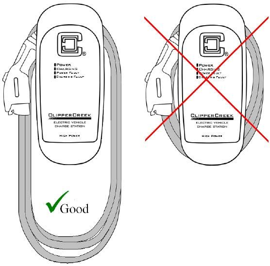
CHARGE CABLE WRAP GUIDELINES
The HCS enclosure body is sculpted to allow the charge cable to
be wrapped around it for convenient storage as well as to keep
the bulk of the cable off of the ground and out of the way. As the
charge cable is comprised of a number of wires, coiling the charge
cable too tightly around the HCS enclosure will result in the charge
cable feeling warmer to the touch than would ordinarily be the
case.
To minimize this effect, it is recommended that the charge cable
be loosely draped around the HCS enclosure body with larger
loops. This will also permit greater convenience in “pulling off”
additional loops if a longer charge cable reach is desired.
Figure 8: Drape the Charge Cable Loosely Around the HCS
Enclosure
30HCS User Manual
WIRING INSTRUCTIONS (Hardwired HCS)
Route the HCS conduit to a nearby junction box. Use the included
½” trade size watertight conduit fitting and sealing washer to
provide a moisture-resistant seal between the conduit fitting
and the junction box. If necessary, drill a ⅞” diameter hole to
accommodate the conduit fitting. For outdoor installations, ensure
the junction box is fully sealed using appropriate electrical grade
silicone sealant.
Figure 9: Wiring the Before connecting the HCS service
HCS in a Junction Box conductors, please carefully read the
section of this manual titled Installation -
Service Connections. If unsure of the type
of power provided at the service panel,
please consult with the local utility or
call a Service Representative for
assistance.
The three supplied HCS-15, 20, 25, 30 or
40 service conductors use stranded 10
AWG 90ºC copper wire. The three
supplied HCS-50, HCS-60, and HCS-80
service conductors use stranded 8 AWG,
90ºC copper wire.
The insulation of each conductor is color
coded for standard 240V AC installation:
Green: Ground
Black: Line 1 (120V AC to Ground)
Red: Line 2 (120V AC to Ground)
Les trois HCS-15, 20, 25, 30 un HCS-40
service conducteurs fournis utilisent
bloqués câble en cuivre 10 AWG 90ºC.
31HCS User Manual
Les trois conducteurs de service HCS-50, HCS-60 et HCS-80
fournis utilisent des câbles toronnés de calibre 8 AWG, 90ºC fil de
cuivre.
L’isolation de chaque conducteur est un code couleur pour
l’installation de 240V AC norme:
Vert: Mise à la Terre
Noir: Ligne 1 (120V AC à Mise à la Terre)
Rouge: Ligne 2 (120V AC à Mise à la Terre)
Los tres conductores de servicio HCS-15, 20, 25, 30 o 40 sumin-
istrados utilizan un cable de cobre trenzado de 10 AWG 90ºC. Los
tres conductores de servicio HCS-50, HCS-60 y HCS-80 suminis-
trados utilizan cable de cobre trenzado de 8 AWG, 90ºC.
El aislamiento de cada conductor tiene un código de color para la
instalación estándar de 240V CA:
Verde: Tierra
Negro: Línea 1 (120V CA a Tierra)
Rojo: Línea 2 (120V CA a Tierra)
32HCS User Manual
RECEPTACLE INSTRUCTIONS (Plug-In HCS)
The plug-in HCS is fitted with either a NEMA 14-50 or 6-50 plug
extending from the bottom of the HCS enclosure. Regulations limit
this plug to a maximum of 12 inches (30.5 cm) in length, including
the plug head. For this reason, the plug-in HCS must be mounted
above the NEMA receptacle and must also be located within 12"
(30.5 cm) of it.
In both NEMA 14-50P and 6-50P configurations, the ground pin is
located at the furthest point on the plug. It is recommended that a
NEMA 14-50R or 6-50R receptacle be oriented accordingly, such
that the ground socket is at the lowest point.
Figure 10: Preferred Orientation of the NEMA Receptacles
Below the Plug-in HCS
33HCS User Manual
GROUNDING INSTRUCTIONS
This product must be grounded. If this product should malfunction,
grounding provides a path of least resistance for electric current to
reduce the risk of electric shock.
HCS Hardwired EVSE Grounding
The hardwired HCS is equipped with three service conductors
shielded by three feet of flexible conduit. This product must be
connected to a grounded, metal, permanent wiring system, or an
equipment-grounding conductor must be run with the circuit
conductors and connected to the ground lead on the product.
HCS Plug-in EVSE Grounding
The plug-in HCS is equipped with a supply cord having an
equipment grounding conductor and a grounding plug. The plug must
be plugged into an appropriate receptacle that is properly installed
and grounded in accordance with all local codes and ordinances.
WARNING: Improper connection of the equipment
grounding conductor may result in a risk of electric shock.
Check with a qualified electrician if doubt exists as to
whether the product is properly grounded. Do not modify the
plug provided with the product – if it will not fit the outlet,
have a proper outlet installed by a qualified electrician.
AVERTISSEMENT: Une mauvaise connexion du
conducteur de terre peut entraîner un risque de choc
électrique. Vérifier avec un électricien qualifié si il existe un
doute quant à savoir si le produit est correctement mis à la
terre. Ne pas modifier la fiche fournie avec le produit – si elle
n’entre pas dans la prise, faites installer une prise adéquate
par un électricien qualifié.
ADVERTENCIA: La conexión incorrecta del conductor de
equipo a tierra puede resultar en un riesgo de descarga
eléctrica. Consulte con un electricista calificado si existe
la duda de si el producto está correctamente conectado a tierra.
No modifique el enchufe suministrado con el producto – si no
entra en el receptáculo, tenga un receptáculo adecuado
instalado por un electricista cualificado.
34HCS User Manual
USING THE PADLOCK
A padlock with three keys is included with ClipperCreek EVSE
when the connector style includes a lock hole. This rust-proof,
solid brass padlock is provided to secure the charge connector to
prevent the vehicle’s charge from being interrupted via removal.
Figure 11: Locking the SAE J1772 Connector with Padlock
Included
Insert Padlock into opening at the top of the
SAE J1772 Connector then close to secure.
Figure 12: Charge Connector Secured with Padlock which
Cannot be Removed from Vehicle without Key
Figure 13: Padlock Used in
Combination with Connector
Holster After Charging
NOTE: This padlock
can also be used in
combination with the
provided connector holster
as a low cost access
control solution. Refer to
Figure 13.
35HCS User Manual
MOVING & STORAGE INSTRUCTIONS
NOTE: Both the hardwired HCS and the plug-in HCS are
intended for fixed installations. For mounting requirements,
consult the Mounting Procedures section of the
Installation Instructions in this manual.
Always turn off input power to the EVSE at the circuit breaker
panel prior to hard-wiring an HCS to or disconnecting an HCS
from the service lines. Likewise, always turn off input power to the
EVSE at the circuit breaker panel prior to plugging an HCS into or
unplugging an HCS from a NEMA socket.
When transporting the EVSE, do not lift or carry the entire unit by
the charge cable. Likewise, do not lift or carry the entire unit by
the flexible conduit and input conductors (HCS) or the NEMA plug
from the plug-in HCS.
The EVSE has a non-operational storage temperature range of
-40°C to +80°C (-40°F to +176°F).
36HCS User Manual
OPTIONAL FEATURES
If the HCS unit being installed is equipped with an optional
feature such as ChargeGuard, Share2, COSMOS, use the
provided HCS Optional Features User Manual.
A digital copy of the HCS Optional Features User Manual can
be found at:
clippercreek.com/installation-manuals
37HCS User Manual
MAINTENANCE
The HCS requires no periodic maintenance other than occasional
cleaning.
WARNING: To reduce the risk of electrical shock or
equipment damage, exercise caution while cleaning
the EVSE and the EV charge connector cable.
1. Turn off the EVSE at the circuit breaker.
2. Unplug the EVSE from the receptacle.
3. Clean the EVSE using a soft cloth lightly
moistened with mild detergent solution. Never use
any type of abrasive pad, scouring powder, or
flammable solvents such as alcohol or benzene.
AVERTISSEMENT: Pour réduire le risque de choc
électrique ou des dommages équipement, user de prudence
lors du nettoyage de l’appareil et le câble du connecteur de
charge EV.
1. Eteignez la équipement au disjoncteur avant de le
nettoyer.
2. Débranchez l’EVSE du recopérable.
3. Nettoyez l’équipement à l’aide d’un chiffon doux
légèrement humidifié avec une solution de détergent
doux. Ne jamais utiliser de tampons abrasifs, de
poudre à récurer ou de solvants inflammables tels
que l ’alcool ou le benzène.
ADVERTENCIA: Para reducir el riesgo de descarga
eléctrica o daños al equipo, debe tener cuidado durante la
limpieza de la unidad y el cable del conector de carga EV.
1. Apague la estación de carga en el interruptor
automático de circuito antes de la limpiar.
2. Desenchufe el EVSE del receptáculo.
3. Limpie la estación de carga con un paño suave
ligeramente humedecido con una solución de
detergente suave. Nunca utilice ningún tipo de
estropajo abrasivo, polvo limpiador o disolventes
inflamables tales como alcohol o bencina.
38HCS User Manual
CUSTOMER SUPPORT
Call a ClipperCreek Service Representative at any time, 24 hours
a day, at the number below. PLEASE HAVE THE MODEL
NUMBER AND SERIAL NUMBER AVAILABLE WHEN
CALLING. This information is printed on the label on the side
of the HCS enclosure. If a call is made after business hours or
on weekends, please leave a name, telephone number, the unit
serial number, and a brief description of the problem. A Service
Representative will call back at the earliest opportunity.
Distributor Service
Number Here
TO CONTACT CLIPPERCREEK DIRECTLY FOR SERVICE,
CALL (877) 694-4194 MONDAY THROUGH FRIDAY
BETWEEN 8:00AM AND 5:00PM PACIFIC TIME.
39HCS User Manual
SPECIFICATIONS
Line Input Power 240V AC single-phase - L1, L2, and Safety Ground.
Voltage & Wiring: 208V AC 3-phase wye-connected - Any two phases and
Safety Ground.
240V AC 3-phase, delta-connected. With center-tap on
one leg, must use only the two phases on either side of
the center-tap. The two phases must both measure 120V
AC to ground. Do not use the third leg (208V “Stinger”).
Supplied Input Pre-installed supplied input conductors of the HCS-15, 20,
Conductors: 25, 30 or 40: L1, L2 and Ground use 3 feet of 10AWG, 90ºC
copper wire.
Pre-installed supplied input conductors of the HCS-50, HCS-60,
and HCS-80: L1, L2 and Ground use 3 feet of 8AWG, 90ºC
copper wire.
Voltage Range: 185V AC to 264V AC
Frequency: 60 Hz
CCID: 20mA
Current & Output HCS Model Circuit Max Output Cable
Power: (at 240V AC) Number Breaker Current Power Length
HCS-15 (hardwired) 15A 12A 2.9 kW 25 ft (7.6m)
HCS-20 (hardwired) 20A 16A 3.8 kW 25 ft (7.6m)
HCS-20R (hardwired) 20A 16A 3.8 kW 25 ft (7.6m)
HCS-25 (hardwired) 25A 20A 4.8 kW 25 ft (7.6m)
HCS-30 (hardwired) 30A 24A 5.8 kW 25 ft (7.6m)
HCS-30R (hardwired) 30A 24A 5.8 kW 25 ft (7.6m)
HCS-40 (hardwired) 40A 32A 7.7 kW 25 ft (7.6m)
HCS-40P + 6-50P 40A/50A 32A 7.7 kW 25 ft (7.6m)
HCS-40P + 14-50P 40A/50A 32A 7.7 kW 25 ft (7.6m)
HCS-40R (hardwired) 40A 32A 7.7kW 25 ft (7.6m)
HCS-40PR + 6-50P 40A/50A 32A 7.7 kW 25 ft (7.6m)
HCS-40PR + 14-50P 40A/50A 32A 7.7 kW 25 ft (7.6m)
HCS-50 (hardwired) 50A 40A 9.6 kW 25 ft (7.6m)
HCS-50P + 6-50P 50A 40A 9.6 kW 25 ft (7.6m)
HCS-50P+14-50P 50A 40A 9.6 kW 25 ft (7.6m)
HCS-60 (hardwired) 60A 48A 11.5 kW 25 ft (7.6m)
HCS-60R (hardwired) 60A 48A 11.5 kW 25 ft (7.6m)
HCS-80 (hardwired) 80A 64A 15.4 kW 25 ft (7.6m)
HCS-80R (hardwired) 80A 64A 15.4 kW 25 ft (7.6m)
NOTE: The maximum current for the vehicle is set by the
duty cycle of the Pilot waveform. Output power is variable
depending upon the HCS model and vehicle demand.
Plugs: An attached NEMA 6-50P or NEMA 14-50P plug is available
on the HCS-40P and HCS-50P.
Dimensions: Dimensions are for the enclosure only:
Height: 19.7 inches (50 cm)
Width: 8.9 inches (22.6 cm)
Depth: 5.3 inches (13.5 cm)
40HCS User Manual
Weight: HCS-15, 20, 25, 30, 40 or HCS-40P with 40A SAE J1772
connector and 25’ length of cable: 6.1kg (13.5 lbs)
HCS-20R, HCS-30R, or HCS-40R with 32A SAE J1772
connector and 25’ length of cable: 6.1kg (13.5 lbs)
HCS-50 or HCS-50P with 40A SAE J1772 connector and 25’
length of cable: 6.3kg (14 lbs)
HCS-60 with 48A SAE J1772 connector and 25’ length of
cable: 9.0 kg (21 lbs)
HCS-60R with 48A SAE J1772 connector and 25’ length of
cable: 8.1 kg (17.8 lbs)
HCS-80 with 64A SAE J1772 connector and 25’ length of
cable: 9.0 kg (21 lbs)
HCS-80R with 64A SAE J1772 connector and 25’ length of
cable: 8.1 kg (17.8 lbs)
Environment: Operating Temperature: -22°F to +122°F (-30°C to +50°C)
Storage Temperature: -40°F to +176°F (-40°C to +80°C)
Enclosure Rating: NEMA 4 - watertight
Agency Approvals: ETL Listed, FCC Part 15 Class B, ENERGY STAR® Certified
Figure 14: HCS Enclosure Dimensions
5.8”
(15 cm)
20” (51 cm)
8.9”
(23 mm)
41Vous pouvez aussi lire