C.A 6501 El modelo Chauvin Arnoux C.A 6501 es el equivalente al modelo AEMC 6501 - AEMC Instruments
←
→
Transcription du contenu de la page
Si votre navigateur ne rend pas la page correctement, lisez s'il vous plaît le contenu de la page ci-dessous
   MEGOHMMETRE


          MEGOHMMETER
          MEGOHMMETER
                                   C.A 6501
         MEGAOHMMETRI             El modelo Chauvin Arnoux
                                   C.A 6501 es el equivalente al
         MEGAOHMETRO
                                   modelo AEMC 6501

FRANÇAIS        Notice de fonctionnement
ENGLISH         User’s manual
DEUTCH          Bedienungsanleitung
IT AL IANO      Manuale d’uso
ESPAÑOL         Manual de instrucciones
Français

Vous venez d’acquérir un mégohmmètre CA 6501 et nous vous remercions de
votre confiance.
Pour obtenir le meilleur service de votre appareil :
     •   lisez attentivement cette notice de fonctionnement,
     •   respectez les précautions d’emploi
SIGNIFICATION DES SYMBOLES UTILISES

                            CA – Courant alternatif
                            Appareil entièrement protégé par une isolation
                            double. Aucun raccordement à la terre de protection
                            n'est requis.
                            Tri sélectif des déchets pour le recyclage des
                            matériels électriques et électroniques au sein de
                            l'Union Européenne.
                            Conformément à la directive WEEE 2002/96/EC : ce
                            matériel ne doit pas être traité comme déchet
                            ménager.

                            Risque de danger. Voir explications de cette notice

                            Risque de choc électrique

Définition des catégories de mesure :
    •      La catégorie de mesure IV correspond aux mesurages réalisés à la
           source de l’installation basse tension.
    •      La catégorie de mesure III correspond aux mesurages réalisés dans
           l’installation du bâtiment.
    •      La catégorie de mesure II correspond aux mesurages réalisés sur les
           circuits directement branchés à l’installation basse tension.
    •      La catégorie de mesure I correspond aux mesurages réalisés sur des
           circuits non reliés directement au réseau.

2                                                                      C.A 6501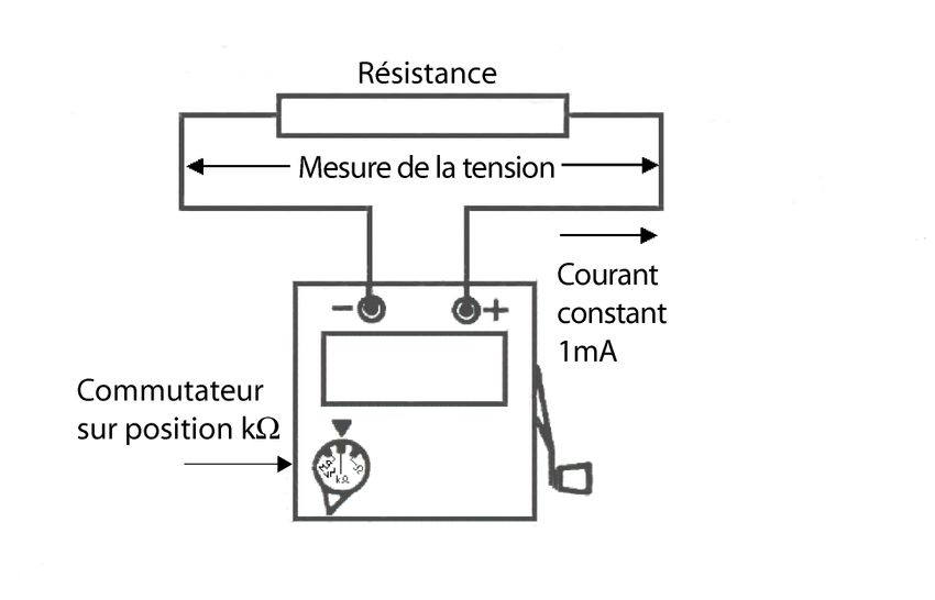
Français

                   PRECAUTIONS D’EMPLOI

Si cet appareil est endommagé ou qu’une pièce est manquante, veuillez contacter
immédiatement le vendeur.
Cet appareil est protégé contre des tensions accidentelles n’excédant pas 600V
par rapport à la terre en catégorie de mesure II ou 300V en catégorie III.
Le non respect des instructions ou précautions d'emploi peut compromettre la
protection assurée par l’appareil.
La présente notice doit être consultée pour chaque symbole de risque de danger
rencontré.

Pour éviter une décharge électrique, une blessure ou un dommage à cet appareil,
et s’assurer que vous utilisez le mégohmmètre sans risque, suivez les conseils de
sécurité ci-dessous :

    •   Cet appareil peut être utilisé à l’intérieur ou à l'extérieur (IP52) dans des
        environnements de degré de pollution au plus égal à 2, à une altitude
        inférieure à 2000m. pour des tensions de 600V CAT II ou 300V CAT III.
    •   Ne jamais utiliser sur des réseaux de tension et de catégories de
        surtension supérieures à celles mentionnées
    •   Avant chaque utilisation, vérifiez l'intégrité du boîtier, de l'isolation des
        cordons et accessoires. Remplacez les cordons endommagés. N’utilisez
        pas l'appareil s’il semble endommagé.
    •   Utilisez des cordons et accessoires conformes aux normes de sécurité
        (IEC 61010-031) de tension et de catégories de surtension au moins
        égales à celles mentionnées
    •   L'utilisation de protections individuelles, appropriées, est vivement
        conseillée. Évitez de travailler seul.
    •   Toute mesure de résistance ou d'isolement ne doit être effectuée que sur
        un circuit isolé et non alimenté.
    •   Suite à une mesure d'isolement, maintenir quelques secondes avant
        déconnexion afin de décharger le circuit testé.
    •   Déconnectez obligatoirement les cordons de l'appareil avant nettoyage,
        remplacement du fusible ou ouverture du boîtier.

C.A 6501                                                                        3
Français
SOMMAIRE
1 PRESENTATION.............................................................................5
2 DESCRIPTION DES DIFFERENTS ELEMENTS, ORGANES DE
COMMANDE ET FONCTIONNALITES ..................................................5
3 MISE EN ŒUVRE - CARACTERISTIQUES :..................................6
3.1 CONSEILS D'UTILISATION .....................................................6
3.2 FONCTIONNEMENT : ..............................................................7
3.2.1 Mesure de MΩ sous 500VDC (± 5% à vide) :....................7
3.2.2 Mesure de kΩ sous 1mADC :............................................7
3.2.3 Mesure de Ω sous 5mADC :..............................................8
3.2.4 Mesure de tension alternative ...........................................8
4 CARACTERISTIQUES GENERALES :...........................................9
5 GARANTIE ......................................................................................11
6 MAINTENANCE ..............................................................................11
6.1 REMPLACEMENT DU FUSIBLE : ............................................11
6.2 STOCKAGE :............................................................................12
6.3 NETTOYAGE :..........................................................................12
6.4 VERIFICATION METROLOGIQUE...........................................12
6.5 REPARATION : ........................................................................12
7 POUR COMMANDER......................................................................13
4 C.A 6501Français
1 PRESENTATION
Le CA 6501 est un appareil de mesure électrique destiné à la mesure de faibles
résistances ( 0 à 100Ω sous 5mADC), des résistances (0 à 500kΩ sous 1mADC) et
à la mesure d'isolement (0.5 à 200MΩ sous 500VDC). La fonction ohmmètre est
protégée contre la présence accidentelle de tension par un fusible à haut pouvoir
de coupure. Un indicateur de présence de tension permet de s'assurer de
l'absence de tension alternative sur le circuit à tester.
Cet appareil est en permanence disponible car ne nécessitant aucun entretien
d'utilisation. Une génératrice à magnéto fournit les différentes tensions de mesure
et de fonctionnement.
2 DESCRIPTION DES DIFFERENTS ELEMENTS,
ORGANES DE COMMANDE ET
FONCTIONNALITES
Bornes de mesure
Fusible
Noire Rouge Voyant lumineux orangé
allumé : signale la bonne
vitesse de rotation de la
magnéto, c'est à dire la
Garde physique servant présence d'une tension
d'appui pour la main gauche pouvant atteindre 500VDC
lors du maniement de la (calibre MΩ) ou celle d'un
manivelle. courant de 1mADC(calibre kΩ)
ou celle d'un courant
de 5mADC (calibre Ω).
Voyant lumineux rouge
allumé : multiplier la lecture
par 10 pour obtenir le Manivelle escamotable
résultat
(sur échelle MΩ, kΩ, Ω)
Vis de réglage
Commutateur de calibre du zéro mécanique
à remettre en position du galvanomètre
MΩ/V∼ après usage
C.A 6501 5Français
3 MISE EN ŒUVRE - CARACTERISTIQUES :
3.1 CONSEILS D'UTILISATION
• Au repos, l'aiguille doit indiquer 0 sur la position voltmètre, sinon la régler
avec la vis centrale noire (voir vue ci-dessus).
• Ne pas connecter l'appareil aux bornes d'un circuit dont la tension est
supérieure à 600VAC ou DC.
• Avant toute mesure de résistance, vérifier que le circuit n'est pas sous
tension (commutateur sur la position voltmètre avant branchement).
• Après chaque mesure de résistance d'isolement, laisser décharger le
circuit (aiguille à 0V : quelques secondes) avant de déconnecter
l'appareil.
Bornes d'entrée mesure :
Elles admettent des fiches de sécurité de
diamètre 4mm.
Indicateurs particuliers :
Un voyant lumineux (Fig.1) situé sur la
droite de l'appareil, de couleur orange,
témoigne de la vitesse correcte de la
magnéto. Lorsqu'il est allumé, la tension
entre les bornes de l'appareil est de 500V,
650V ou 10VDC (sans charge), selon la
position du commutateur.
Un voyant lumineux rouge (Fig. 2) situé sur
la gauche de l'appareil signale le
changement automatique de calibre.
Lorsqu'il est allumé, il faut multiplier la
lecture par 10 pour obtenir le résultat.
6 C.A 6501Français
3.2 FONCTIONNEMENT :
3.2.1 Ω sous 500VDC (±
Mesure de MΩ ± 5% à vide) :
La mesure est réalisée sous
un tension de 500VDC, au
dessus de 0,5MΩ mesurés.
Il y a changement de
coefficient de lecture en
valeur montante : 20MΩ
(passe en lecture X10), et
changement de coefficient de
lecture en valeur descendante
: 5,5MΩ (passe en lecture
X1).
3.2.2 Ω sous 1mADC :
Mesure de kΩ
La mesure est réalisée sous
un courant de 1mADC, de 0 à
500kΩ mesurés (650VDC
max. à vide).
Il y a changement de
coefficient de lecture en
valeur montante : 50kΩ
(passe en lecture X10), et
changement de coefficient de
lecture en valeur descendante
: 45kΩ (passe en lecture X1).
C.A 6501 7Français
3.2.3 Mesure de Ω sous 5mADC :
La mesure est réalisée sous
un courant de 5mADC, de 0 à
100Ω mesurés (10VDC max. à
vide).
Il y a changement de
coefficient de lecture en
valeur montante : 10Ω (passe
en lecture X10), et
changement de coefficient de
lecture en valeur descendante
: 9Ω (passe en lecture X1).
3.2.4 Mesure de tension alternative
La mesure de tension
alternative s’effectue de 0 à
600VAC en une seule gamme
(impédance d'entrée :
100kΩ), commutateur en
position V.
8 C.A 6501Français
4 CARACTERISTIQUES GENERALES :
Dimensions : 120mm x 120mm, hauteur 130mm.
Masse : 1,06kg.
Degré de protection enveloppe :
IP54 avec couvercle et IP52 sans couvercle selon IEC
60529 (Ed. 92)
Alimentation : Cet appareil est alimenté par une génératrice à magnéto
qui fournit les différentes tensions de mesure et de
fonctionnement (vitesse de rotation : environ 140 tours /
minute).
Le voltmètre est alimenté par l'entrée mesure et ne
nécessite donc pas de manipulation de la manivelle.
Caractéristiques dans le domaine de référence (23°C ± 3°C) :
Calibres Caractéristiques dans la plage de référence
MΩ ± 2.5% de la longueur d'échelle
kΩ ± 2.5% de la longueur d'échelle
Ω ± 2.5% de la longueur d'échelle
Volts ~ ± 3% de la longueur d'échelle de 45 à 450Hz
MΩ Tension de mesure : 500V
MΩ Courant de court-circuit ≤ 5mA
kΩ Courant régulé à 1mA
Ω Courant régulé à 5mA
C.A 6501 9Français
Variations dans le domaine d’utilisation : grandeurs d’influence.
Calibres Erreurs dans la plage d'utilisation (-10 à + 45°C) jusqu'à
50%HR et à +35°C jusqu'à 75%HR)
MΩ +1.25% / 10°C
kΩ +1.25% / 10°C
Ω +1.25% / 10°C
Volts ~ +1.5% / 10°C de 45Hz à 450Hz
MΩ ± 5%
Surcharges - protections :
Calibre Ω : 600VAC/DC maxi. : protection par fusible rapide F 0,2A -
600V - HPC (6,3x32mm) à partir de 100V, en dessous de
100V surcharge limitée à 10 secondes.
Ω:
Calibre kΩ 600VAC/DC maxi.
10 C.A 6501Français
Conformité aux normes internationales :
Sécurité électrique selon IEC 61010-1 (Ed. 2 de 2001).
Sécurité électrique selon IEC 61010-2-031 (Ed. 2 de 2002).
Mesure selon IEC 61557 (Ed. 2 de 2007) parties 1 et 4
Tension maximale assignée : 600V
Caractéristiques assignées : catégorie de mesure III, 300V ou catégorie de
mesure II, 600V par rapport à la terre ,
degré de pollution 2.
Compatibilité électromagnétique :
L’appareil est conforme aux exigences relatives à la CEM selon NF
EN 61326-1 (Ed. 97) + A1(Ed. 98) + A2 (Ed. 2001).
5 GARANTIE
Notre garantie s'exerce, sauf stipulation expresse, pendant deux ans,
après la date de mise à disposition du matériel (extrait de nos conditions
générales de vente, communiquées sur demande).
6 MAINTENANCE
6.1 REMPLACEMENT DU FUSIBLE :
Pour votre sécurité, encliqueter la manivelle dans le logement prévu à cet
effet et déconnecter obligatoirement les cordons de toute installation
électrique ainsi que de l'appareil.
A l'aide d'un tournevis plat, appuyez et tournez d'un quart de tour anti-
horaire pour libérer le fusible. Ne remplacer que par un fusible de
caractéristiques identiques.
Fusible : F 0,2A / 600V / HPC Réf : P01297095
C.A 6501 11Français
6.2 STOCKAGE :
Encliqueter la manivelle dans le logement prévu à cet effet, mettre en place
le couvercle de protection.
Aucun élément ne nécessite son retrait pour un stockage prolongé.
6.3 NETTOYAGE :
Le CA6501 doit être déconnecté de toute installation électrique.
Pour nettoyer le boîtier, utiliser un chiffon légèrement imbibé d'eau
savonneuse. Essuyer avec un chiffon humide non ruisselant. Ensuite,
sécher rapidement avec un chiffon sec ou de l'air pulsé.
6.4 VERIFICATION METROLOGIQUE
Comme pour tous les appareils de mesure ou d'essai, une vérification
périodique est nécessaire.
Pour les vérifications et étalonnages de vos appareils, adressez-vous à nos
laboratoires de métrologie accrédités COFRAC ou aux Centres Techniques
MANUMESURE.
Renseignements et coordonnées sur demande :
Tél. :02 31 64 51 43 Fax. : 02 31 64 51 09
6.5 REPARATION :
Réparation :Le fabricant ne pourra être tenu pour responsable de tout
accident survenu suite à une réparation effectuée en dehors de son service
après-vente ou des réparateurs agréés.
Réparation sous garantie et hors garantie.
Adressez vos appareils à l'un des Centres Techniques régionaux
MANUMESURE, agréés CHAUVIN ARNOUX
Renseignements et coordonnées sur demande :
Tél. :02 31 64 51 43 Fax. : 02 31 64 51 09
12 C.A 6501Français
Réparation hors de France métropolitaine : Pour toute intervention sous
garantie ou hors garantie, retournez l'appareil à votre distributeur.
7 POUR COMMANDER
C.A 6501 Mégohmmètre ................................................................ P01132503
Livré avec :
• 1 cordon coudé / droit 1,5m noir.
• 1 cordon coudé / droit 1,5m rouge.
• 1 Pince crocodile noire.
• 1 Pince crocodile rouge.
• 1 Pointe de touche noire.
• 1 notice de fonctionnement 5 langues
• 1 sacoche de transport
RECHANGES :
• Fusible 0,2A – 600V – HPC – 6,3 x 32mm ........................ P01297095
• Sacoche de transport.......................................................... P01298006
C.A 6501 13English
You have just purchased a CA 6501 megohmmeter; thank you for your
confidence.
For best results from your device:
• read this user manual attentively,
• observe the precautions for its use.
MEANINGS OF THE SYMBOLS USED
AC – Alternating current
Instrument fully protected by double insulation. No
connection to the protective earth is necessary.
Selective sorting of wastes for the recycling of
electrical and electronic equipment within the
European Union.
In conformity with directive WEEE 2002/96/EC: this
equipment must not be treated as household waste.
Danger. See explanations in this manual
Risk of electric shock
Definitions of the measurement categories:
• Measurement category IV corresponds to measurements made at the
source of the low-voltage installation.
• Measurement category III corresponds to measurements made in the
installation of the building.
• Measurement category II corresponds to measurements made on
circuits directly connected to the low-voltage installation.
• Measurement category I corresponds to measurements made on circuits
not directly connected to the network.
14 C.A 6501English
PRECAUTIONS FOR USE
If this instrument is damaged or a part is missing, please contact the seller
immediately.
This instrument is protected against accidental voltages up to 600V with respect
to earth in measurement category II, 300V in category III.
Failure to observe the instructions or the precautions for use may compromise the
protection provided by the instrument.
Please refer to this manual for each danger symbol encountered.
To avoid an electric discharge, injury, or damage to this instrument, and make
sure that you are using the megohmmeter in a risk-free manner, follow the safety
recommendations below:
• This instrument can be used indoors or out (IP52) in environments where
the degree of pollution does not exceed 2, at an altitude of less than
2000m, with voltages up to 600V (CAT II) or 300V (CAT III).
• Never use on a network of which the voltage or overvoltage category
exceeds the stated values
• Before each use, check the integrity of the housing and of the insulation
of the leads and accessories. Replace any damaged cords. Do not use
the instrument if it seems damaged.
• Use leads and accessories satisfying safety standards (IEC 61010-031)
for voltages and overvoltage categories at least equal to those
mentioned.
• The use of suitable personal protective equipment is strongly
recommended. Avoid working alone.
• Resistance and insulation measurements must be made only on circuits
that are isolated and not live.
• Following an insulation measurement, leave the measurement leads
connected for a few seconds before disconnecting in order to discharge
the circuit tested.
• Disconnect the cords from the instrument before cleaning, changing the
fuse, or opening the housing.
C.A 6501 15English
CONTENTS
1 PRESENTATION.............................................................................17
2 DESCRIPTION OF THE VARIOUS PARTS, CONTROLS, AND FUNCTIONS
17
3 USE - CHARACTERISTICS: ...........................................................18
3.1 RECOMMENDATIONS.............................................................18
3.2 OPERATION:............................................................................19
3.2.1 MΩ measurement at 500VDC: ..........................................19
3.2.2 kΩ measurement at 1mADC: ............................................19
3.2.3 Ω measurement at 5mADC: ..............................................20
3.2.4 AC voltage measurement ..................................................20
4 GENERAL CHARACTERISTICS: ...................................................21
5 WARRANTY ....................................................................................23
6 MAINTENANCE ..............................................................................23
6.1 REPLACING THE FUSE: .........................................................23
6.2 STORAGE: ...............................................................................24
6.3 CLEANING: ..............................................................................24
6.4 METROLOGICAL CHECK........................................................24
6.5 REPAIR: ...................................................................................24
7 TO ORDER ......................................................................................25
16 C.A 6501English
1 PRESENTATION
The CA 6501 is an electrical measuring instrument intended for the measurement
of low resistance values (0 to 100Ω at 5mADC), of resistances (0 to 500kΩ at
1mADC), and for insulation measurements (0.5 to 200MΩ at 500VDC). The
ohmmeter function is protected against the accidental presence of a voltage by a
high-breaking-capacity fuse. A voltage-present indicator serves to make sure that
there is no AC voltage in the circuit to be tested.
This instrument is ready for use at all times because it requires no operating
maintenance. A magneto generator provides the various measurement and
operating voltages.
2 DESCRIPTION OF THE VARIOUS PARTS,
CONTROLS, AND FUNCTIONS
Measurement terminals
Fuse
Black Red Orange indicator lit: indicates
that magneto speed of rotation
is OK, i.e. that there is a voltage
of up to 500VDC (MΩ range) or
Physical guard used a current of 1mADC (kΩ range)
to support the left hand or a current of 5mADC (Ω range).
when operating the
crank.
Red indicator
lit: multiply the reading
by 10 to obtain the result Retractable crank
(on MΩ, kΩ, Ω scales)
Screw for adjustment
Range switch; of the mechanical zero
set back to of the galvanometer
MΩ/V∼ after using
C.A 6501 17English
3 USE - CHARACTERISTICS:
3.1 RECOMMENDATIONS
The needle must indicate 0 when at rest in the voltmeter setting; if not, adjust
it using the black screw in the centre (see picture above).
Do not connect the instrument to the terminals of a circuit of which the
voltage exceeds 600VAC or DC.
Before any resistance measurement, check that the circuit is not live (switch
set to voltmeter before connection).
After each insulation resistance measurement, let the circuit discharge
(needle on 0V; this takes a few seconds) before disconnecting the
instrument.
Measurement input terminals:
These accept safety plugs 4mm in
diameter.
Other indicators:
An orange indicator (Fig. 1) on the right
side of the instrument indicates that the
speed of the magneto is correct. When it is
lit, the voltage between the terminals of the
instrument is 500V, 650V, or 10VDC (no-
load), depending on the setting of the
switch.
A red indicator (Fig. 2) on the left side of
the instrument indicates the automatic
change of range. When it is lit, multiply the
reading by 10 to obtain the result.
18 C.A 6501English
3.2 OPERATION:
3.2.1 Ω measurement at 500VDC:
MΩ
The measurement is made at
a voltage of 500VDC above
0.5MΩ measured.
There is a change of reading
coefficient for rising values:
20MΩ (changes to X10
reading), and a change of
reading coefficient for falling
values: 5.5MΩ (changes to
X1 reading).
3.2.2 Ω measurement at 1mADC:
kΩ
The measurement is made
with a current of 1mADC,
from 0 to 500kΩ measured
(650VDC max. no-load).
There is a change of reading
coefficient for rising values:
50kΩ (changes to X10
reading), and a change of
reading coefficient for falling
values: 45kΩ (changes to X1
reading).
C.A 6501 19English
3.2.3 Ω measurement at 5mADC:
The measurement is made
with a current of 5mADC, from
0 to 100Ω measured (10VDC
max. no-load).
There is a change of reading
coefficient for rising values:
10Ω (changes to X10
reading), and a change of
reading coefficient for falling
values: 9Ω (changes to X1
reading).
3.2.4 AC voltage measurement
The AC voltage measurement
is from 0 to 600VAC in a single
range (input impedance:
100kΩ), switch set to V.
20 C.A 6501English
4 GENERAL CHARACTERISTICS:
Dimensions: 120mm x 120mm, height 130mm.
Mass: 1.06kg.
Degree of protection by housing:
IP54 with cover and IP52 without cover as per IEC
60529 (Ed. 92)
Power supply: This instrument is supplied by a magneto generator that
provides the various measurement and operating
voltages (speed of rotation: approximately 140 rpm).
The voltmeter is supplied by the measurement input and
so there is no need to operate the crank.
Characteristics in the reference domain (23°C ±3°C):
Ranges Characteristics in the reference range
MΩ ± 2.5% of full scale
kΩ ± 2.5% of full scale
Ω ± 2.5% of full scale
Volt~ ± 3% of full scale from 45 to 450Hz
MΩ Measurement voltage: 500V
MΩ Short-circuit current ≤ 5mA
kΩ Current regulated to 1mA
Ω Current regulated to 5mA
C.A 6501 21English
Variations in the domain of use: quantities of influence.
Ranges Errors in the range of use (-10 to+45°C) up to 50% RH and to
+35°C up to 75% RH)
MΩ +1.25% / 10°C
kΩ +1.25% / 10°C
Ω +1.25% / 10°C
Volt ~ +1.5% / 10°C, from 45Hz to 450Hz
MΩ ± 5%
Overloads - protection:
Ω range: 600VAC/DC max.: protection by fast-blow fuse F 0.2A,
600V, HBC (6.3x32mm) from 100V, below 100V overload
limited to 10 seconds.
Ω range:
kΩ 600VAC/DC max.
22 C.A 6501English
Compliance with international standards:
Electrical safety in accordance with IEC 61010-1 (Ed. 2 of 2001).
Electrical safety in accordance with IEC 61010-2-031 (Ed. 2 of 2002).
Measurement in accordance with IEC 61557 (Ed. 2 of 2007), parts 1 and 4
Rated maximum voltage: 600V
Rated characteristics: measurement category III, 300V, or
measurement category II, 600V with respect
to earth,
degree of pollution 2.
Electromagnetic compatibility:
The instrument complies with EMC requirements as per NF EN 61326-1
(Ed. 97) + A1 (Ed. 98) + A2 (Ed. 2001).
5 WARRANTY
Our warranty applies, except as otherwise expressly stipulated, for two
years counting from the date of availability of the equipment (extract from
our General Terms of Sale, communicated on request).
6 MAINTENANCE
6.1 REPLACING THE FUSE:
For your safety, snap the crank into the recess provided for this purpose; be
sure to disconnect the leads from any electrical installation and from the
instrument.
Using a flat blade screwdriver, press and turn a quarter turn anti-clockwise to
release the fuse. Replace only with a fuse having identical characteristics.
Fuse: F 0.2A/600V/HBC P/N: P01297095
C.A 6501 23English
6.2 STORAGE:
Snap the crank into the recess provided for this purpose; fit the protective
cover.
There is nothing that need be removed for prolonged storage.
6.3 CLEANING:
The CA6501 must be disconnected from any electrical installation.
To clean the housing, use a cloth moistened with soapy water. Wipe off with
a damp cloth. Then dry rapidly with a dry cloth or forced air.
6.4 METROLOGICAL CHECK
Like all measuring and testing devices, the multimeter must be checked
periodically.
For checks and calibrations, get in touch with our COFRAC-accredited
metrology laboratories or with MANUMESURE Technical Centres.
Information and coordinates on request:
Tel.: +33 (0)2 31 64 51 43 Fax.: +33 (0)2 31 64 51 09
6.5 REPAIR:
Repair: The manufacturer cannot be held liable for any accident
following a repair other than by its customer service department or an
approved repairer.
Repair, under warranty or not
Send your instrument to one of the CHAUVIN ARNOUX-approved
MANUMESURE Regional Technical Centres
Information and coordinates on request:
Tel.: +33 (0)2 31 64 51 43 Fax.: +33 (0)2 31 64 51 09
Repair outside of mainland France: For any repair, whether under
warranty or not, send the instrument back to your dealer.
24 C.A 6501English
7 TO ORDER
C.A 6501 Megohmmeter ................................................................. P01132503
Delivered with:
• 1 1.5m black angled / straight cord.
• 1 1.5m red angled / straight cord.
• 1 Black alligator clip.
• 1 Red alligator clip.
• 1 Black probe tip.
• 1 user guide in 5 languages
• 1 carrying bag
SPARES:
• Fuse, 0.2A, 600V, HBC, 6,3 x 32mm P01297095
• Carrying bag P01298006
C.A 6501 25Deutsch
Sie haben ein CA 6501 Megohmmeter erstanden, wir danken Ihnen für Ihr
Vertrauen.
Für die Erlangung eines optimalen Betriebsverhaltens Ihres Gerätes:
• Lesen Sie bitte diese Betriebsanleitung aufmerksam durch und
• beachten Sie bitte die Anwendungshinweise.
BEDEUTUNG DER SYMBOLE
Wechselstrom
Das Gerät ist schutzisoliert bzw. durch eine verstärkte
Isolierung geschützt. Keine Schutzerde erforderlich.
Weist darauf hin, dass dieses Gerät in der EU gemäß
der EC-Richtlinie für Elektro- und Elektronikschrott
WEEE 2002/96/EC entsorgt und recycelt werden
muss.
Gefahr! Bitte lesen Sie die Erklärungen in dieser
Anleitung.
Stoßspannungsgefahr
Definition der Messkategorien:
• Messkategorie IV entspricht Messungen an Niederspannungsanlagen.
• Messkategorie III entspricht Messungen für elektrische Anlagen in
Gebäuden.
• Messkategorie II entspricht Messungen an Geräten, die direkt an
Niederspannungsanlagen angeschlossen sind.
• Messkategorie I entspricht Messungen an Geräten, die nicht direkt an
das Stromnetz angeschlossen sind.
26 C.A 6501Deutsch
BEDIENUNGSHINWEISE
Materialfehler oder fehlende Teile melden Sie bitte umgehend Ihrem Händler.
Das Gerät besitzt einen Überlastschutz 600V Erde (Messkategorie II) und 300V in
Messkategorie III.
Dieses Gerät darf nur anleitungsgemäß verwendet werden, andernfalls könnte
der Geräteschutz beeinträchtigt werden.
Lesen Sie bitte jedes Mal in dieser Anleitung nach, wenn Sie auf ein
Gefahrensymbol stoßen.
Für die gefahrlose Anwendung dieses Megohmmeters, und um elektrische
Entladungen, Körperverletzungen bzw. Beschädigung des Geräts zu verhindern,
befolgen Sie bitte diese Sicherheitshinweise:
• Dieses Gerät kann in Innenräumen und im Freien (IP52), bis zu einem
Verschmutzungsgrad 2, auf bis zu 2000m Höhe und bei Spannungen
600V CAT II bzw. 300V CAT III verwendet werden.
• Verwenden Sie das Gerät niemals in höherwertigen Spannungsnetzen
und Überspannungskategorien als angegeben!
• Prüfen Sie vor jedem Einsatz nach, ob das Gehäuse, die Isolierung der
Schnüre und das Zubehör einwandfrei sind. Tauschen Sie beschädigte
Drähte aus. Beschädigte Geräte niemals verwenden!
• Verwenden Sie nur Drähte und Zubehör, das mindestens den
Sicherheitsnormen (IEC 61010-031) für die angegebenen Spannungen
und Überspannungskategorien entspricht.
• Wir empfehlen dringend, geeignete Schutzkleidung zu tragen. Arbeiten
Sie möglichst nicht alleine.
• Widerstands- und Isolationsmessung nur in isolierten, nicht versorgten
Kreisen.
• Nach einer Isolationsmessung müssen Sie die Prüfdrähte vor dem
Abschalten einige Sekunden lang angeschlossen bleiben, damit sich der
geprüfte Kreis entladen kann.
• Reinigung, Sicherungswechsel und Öffnen des Gehäuses nur bei
abgenommenen Drähten!
C.A 6501 27Deutsch
INHALTSÜBERSICHT
1 PRÄSENTATION.............................................................................29
2 BESCHREIBUNG DER KOMPONENTEN, STEUERORGANE UND
FUNKTIONALITÄTEN............................................................................29
3 INBETRIEBNAHME – EIGENSCHAFTEN:.....................................30
3.1 BEDIENUNG ............................................................................30
3.2 BETRIEB: .................................................................................31
3.2.1 MΩ-Messung 500VDC: .....................................................31
3.2.2 kΩ-Messung 1mADC:........................................................31
3.2.3 Ω-Messung 5mADC: .........................................................32
3.2.4 Wechselspannungsmessungen ........................................32
4 ALLGEMEINE TECHNISCHE DATEN ............................................33
5 GARANTIE ......................................................................................35
6 WARTUNG UND PFLEGE DES GERÄTS ......................................35
6.1 ERSETZEN DER SICHERUNG................................................35
6.2 LAGERUNG:.............................................................................36
6.3 REINIGUNG: ............................................................................36
6.4 EICHUNG .................................................................................36
6.5 REPARATUR:...........................................................................36
7 BESTELLANGABEN, LIEFERUMFANG ........................................37
28 C.A 6501Deutsch
1 PRÄSENTATION
C.A 6501 ist ein Elektromessgerät zum Messen kleiner Widerstände (0 bis 100Ω
bei 5mADC), Widerstände (0 bis 500kΩ bei 1mADC) und Isolationsmessung (0.5 bis
200MΩ bei 500VDC). Die Ohmmeter-Funktion ist mit einer NH-Sicherung vor
unbeabsichtigen Spannungen geschützt. Über eine Spannungsanzeige wird
sichergestellt, dass im Prüfkreis keine Wechselspannung vorhanden ist.
Das Gerät muss nicht gewartet werden und steht daher immer zur Verfügung. Ein
Induktorgenerator generiert die verschiedenen Mess- und Betriebsspannungen.
2 BESCHREIBUNG DER KOMPONENTEN,
STEUERORGANE UND FUNKTIONALITÄTEN
Messbuchsen
Sicherung
Schwarz Rot Orange Leuchtanzeige
leuchtet:
Drehgeschwindigkeit in
Ordnung, d.h. bis zu
Auf dieser Abschirmung 500VDC Spannung
ruht die linke Hand
(Messbereich MΩ) bzw.
beim Kurbeln.
Strom
1mADC (Messbereich MΩ)
oder Strom 5mADC
(Messbereich Ω).
Rote Leuchtanzeige
leuchtet: für das Ergebnis
den Ableswert mit 10 Klappkurbel
multiplizieren
(Messbereich MΩ, kΩ, Ω)
Schraube zum
Messbereichumschalter mechanischen
nach dem Einsatz wieder Nullstellen des
auf MΩ/V∼ stellen Galvanometers
C.A 6501 29Deutsch
3 INBETRIEBNAHME – EIGENSCHAFTEN:
3.1 BEDIENUNG
• In Ruhestellung muss die Nadel am Voltmeter auf 0 stehen, andernfalls
die Position mit der schwarzen Schraube (siehe Abb. oben) einstellen.
• Das Gerät darf nicht an einen Kreis angeschlossen werden, dessen
Spannung über 600VAC oder DC beträgt.
• Vor dem Messen von Widerständen muss sichergestellt werden, dass
der Kreis nicht unter Spannung steht (Schalter vor dem Anschließen auf
Voltmeter).
• Nach einer Isolationsmessung lässt man vor dem Abschalten den
geprüften Kreis entladen (Nadel auf 0V: einige Sekunden lang).
Messbuchse:
Für 4mm Sicherheitsstecker.
Spezifische Anzeigen:
Eine orange Leuchtanzeige (Abb.1) rechts
am Gerät zeigt die korrekte
Drehgeschwindigkeit des Induktors an.
Wenn die Anzeige leuchtet, beträgt die
Spannung an den Gerätebuchsen 500V,
650V oder 10VDC (keine Last), je nach
Schalterstellung.
Die rote Leuchtanzeige (Abb. 2) links am
Gerät zeigt die automatische Umschaltung
des Messbereichs an. Wenn diese Anzeige
leuchtet, muss der Ablesewert mit 10
multipliziert werden.
30 C.A 6501Deutsch
3.2 BETRIEB:
3.2.1 Ω-Messung 500VDC:
MΩ
Die Messung erfolgt ab
0,5MΩ bei 500VDC Spannung.
Bei steigenden Werten ändert
sich der Ablesefaktor: 20MΩ
(Ablesewert X10). Ebenso bei
fallenden Werten: 5,5MΩ
(Ablesewert X1).
3.2.2 Ω-Messung 1mADC:
kΩ
Messung bei 1mADC
Stromwert, Messungen 0 bis
500kΩ (650VDC maxi
Leerlauf).
Bei steigenden Werten ändert
sich der Ablesefaktor: 50kΩ
(Ablesewert X10). Ebenso bei
fallenden Werten: 45kΩ
(Ablesewert X1).
C.A 6501 31Deutsch
3.2.3 Ω-Messung 5mADC:
Messung bei 5mADC
Stromwert, Messungen 0 bis
100Ω (10VDC maxi Leerlauf).
Bei steigenden Werten ändert
sich der Ablesefaktor: 10Ω
(Ablesewert X10). Ebenso bei
fallenden Werten: 9Ω
(Ablesewert X1).
3.2.4 Wechselspannungsmessungen
Wechselspannungsmessung
0 bis 600VAC in einer Reihe
(Eingangsimpedanz: 100kΩ),
Schalter auf V.
32 C.A 6501Deutsch
4 ALLGEMEINE TECHNISCHE DATEN
Abmessungen: 120mm x 120mm, Höhe 130mm.
Gewicht: 1,06kg.
Schutzgrad Hülle:
IP54 mit Deckel und IP52 ohne Deckel gemäß IEC
60529 (Ed. 92)
Stromversorgung: Ein Induktorgenerator generiert die verschiedenen
Mess- und Betriebsspannungen.
(Drehgeschwindigkeit: ca. 140U/min).
Voltmeterversorgung über den Messeingang, ein
Betätigen der Kurbel ist daher nicht erforderlich.
Eigenschaften im Referenzbereich (23°C ± 3°C):
Messbereiche Eigenschaften im Referenzbereich
MΩ ± 2.5% des Vollmaßes
kΩ ± 2.5% des Vollmaßes
Ω ± 2.5% des Vollmaßes
Volt ~ ± 3% des Vollmaßes bei 45 bis 450Hz
MΩ Messspannung: 500V
MΩ Kurzschlussstrom: ≤ 5mA
kΩ Stromwert auf 1mA
Ω Stromwert auf 1mA
C.A 6501 33Deutsch
Schwankungen im Einsatzbereich: Einflussgrößen.
Messbereiche Fehler im Einsatzbereich (-10 bis + 45°C) bis 50% RF
und bei + 35°C bis 75% RF)
MΩ +1.25% / 10°C
kΩ +1.25% / 10°C
Ω +1.25% / 10°C
Volt ~ +1.5% / 10°C, 45Hz bis 450Hz
MΩ ± 5%
Überlastschutz:
Messbereich Ω: 600VAC/DC Maximum Schutz mit flinker Sicherung
F 0,2A - 600V - HPC (6,3 x 32mm) ab 100V, unter
100V Überlast bis 10 Sekunden.
Ω: 600VAC/DC Maximum
Messbereich kΩ
34 C.A 6501Deutsch
Konformität mit Internationalen Normen
Elektrische Sicherheit gem. IEC 61010-1 (Ausg. 2 Jahr 2001).
Elektrische Sicherheit gem. IEC 61010-2-031 (Ausg. 2 Jahr 2002)
Messung gem. IEC 61557 (Ausg. 2 Jahr 2007), 1 und 4
max. zul. Nennspannung: 600V
Spezifikationen: Messkategorie III, 300V (bzw. Messkategorie
II), 600V Erde.
Verschmutzungsgrad: 2
Elektromagnetische Verträglichkeit (EMV)
Das Gerät erfüllt die EMV-Richtlinien, sowie die Norm NF EN 61326-1
(Ausg. 97) + A1 (Ausg. 98) + A2 (Ausg. 2001).
5 GARANTIE
Außer ausdrücklich anders lautenden Angaben beträgt die Garantiefrist für
unsere 2 Jahre nach Bereitstellung des Geräts beim Kunden (Auszug aus
unseren allgemeinen Verkaufsbedingungen, die wir Ihnen auf Anfrage
gerne zusenden).
6 WARTUNG UND PFLEGE DES GERÄTS
6.1 ERSETZEN DER SICHERUNG
Zu Ihrer eigenen Sicherheit legen Sie die Kurbel in ihr Gehäuse ein und
nehmen Sie unbedingt die Drähte von allen Elektroanlagen und vom Gerät
ab.
Mit einem flachen Schraubendreher drücken und gegen den Uhrzeigersinn
die Sicherung freidrehen. Die Sicherung nur durch ein identisches Modell
ersetzen.
Sicherung: F 0,2A / 600V / HPC Ref: P01297095
C.A 6501 35Deutsch
6.2 LAGERUNG:
Legen Sie die Kurbel in ihr Gehäuse ein und schließen Sie den Deckel.
Auch bei längerer Lagerung brauchen keine Komponenten
herausgenommen werden.
6.3 REINIGUNG:
CA6501 darf nicht an elektrische Anlagen angeschlossen sein.
Das Gerätegehäuse wird mit einem leicht mit Seifenwasser angefeuchteten
Tuch gereinigt. Mit einem ausgewundenen feuchten Lappen abwischen.
Trocknen Sie das Gerät danach schnell mit einem trockenen Tuch oder
einem Warmluftgebläse.
6.4 EICHUNG
Wie auch bei anderen Mess- oder Prüfgeräten ist eine regelmäßige
Geräteüberprüfung erforderlich.
Für die Überprüfungen und Eichungen stehen Ihnen unsere zugelassenen
Metrologie-Laboratorien von COFRAC oder die Geschäftsstellen von
MANUMESSUNG gerne zur Verfügung.
Auskünfte und Adressen stehen auf Anfrage hin zur Verfügung:
Tel.:+33 (0)2 31 64 51 43 Fax.: +33 (0)2 31 64 51 09
6.5 REPARATUR:
Reparatur: Der Hersteller haftet keinesfalls für Schäden, die durch
Reparaturen außerhalb seines Kundendienstnetzes oder durch nicht von
ihm zugelassene Reparaturdienste verursacht wurden.
Reparatur während und außerhalb der Garantiedauer.
Senden Sie Ihre Geräte an eine der Geschäftsstellen von MANUMESSUNG
mit CHAUVIN ARNOUX Zulassung.
Auskünfte und Adressen stehen auf Anfrage hin zur Verfügung:
Tel.:+33 (0)2 31 64 51 43 Fax.: +33 (0)2 31 64 51 09
Reparatur außerhalb von Frankreich: Für während oder außerhalb der
Garantiedauer erforderliche Eingriffe senden Sie das Gerät bitte an den
Händler zurück.
36 C.A 6501Deutsch
7 BESTELLANGABEN, LIEFERUMFANG
C.A 6501 Megohmmeter ................................................................. P01132503
Lieferumfang:
• 1 schwarze Messleitung 1,5m (gebogen-gerade)
• 1 rote Messleitung 1,5m (gebogen-gerade)
• 1 schwarze Krokodilklemme
• 1 rote Krokodilklemme
• 1 schwarze Prüfspitze
• 1 Betriebsanleitung in 5 Sprachen
• 1 Transporttasche
ERSATZTEILE:
• Sicherung 0,2A – 600V – HPC – 6,3 x 32mm P01297095
• Transporttasche.................................................................. P01298006
C.A 6501 37Italiano
Avete appena acquisito un megaohmmetro CA 6501 e vi ringraziamo della vostra
fiducia.
Per ottenere dal vostro apparecchio le migliori prestazioni:
• Leggete attentamente il presente libretto di funzionamento,
• Rispettate le precauzioni d’uso.
SIGNIFICATO DEI SIMBOLI UTILIZZATI
CA – Corrente alternata
Apparecchio interamente protetto da un doppio
isolamento. Non si richiedono raccordi a terra
(protezione).
Cernita selettiva dei rifiuti per il riciclo dei materiali
elettrici ed elettronici in seno all'Unione Europea.
Conformemente alla direttiva WEEE 2002/96/EC:
questo materiale non va trattato come rifiuto
domestico.
Rischio di pericolo. Consultare le spiegazioni del
presente libretto.
Rischio d’elettrocuzione
Definizione delle categorie di misura:
• La categoria di misura IV corrisponde alle misurazioni effettuate alla
sorgente dell’impianto bassa tensione.
• La categoria di misura III corrisponde alle misurazioni effettuate
nell’impianto dell’edificio.
• La categoria di misura II corrisponde alle misurazioni effettuate sui
circuiti direttamente allacciati all’impianto bassa tensione.
• La categoria di misura I corrisponde alle misurazioni effettuate su circuiti
non direttamente collegati alla rete.
38 C.A 6501Italiano
PRECAUZIONI D’USO
Se l’apparecchio è danneggiato o se manca un pezzo, contattare
immediatamente il venditore.
L’apparecchio è protetto contro le tensioni fortuite non superiori a 600V rispetto
alla terra in categoria di misura II o 300V in categoria III.
Il mancato rispetto delle istruzioni o precauzioni d'impiego può compromettere la
protezione garantita dall’apparecchio.
Consultare il presente libretto per ogni simbolo di rischio di pericolo incontrato.
Per evitare una scarica elettrica, un incidente o un danno al presente
apparecchio, e per accertarsi del corretto uso del megaohmmetro (senza rischi),
seguite i consigli di sicurezza forniti più avanti:
• E’ possibile utilizzare l’apparecchio all’interno o all'esterno (IP52) in
ambienti in cui il grado massimo d’inquinamento è 2 e l’altitudine
inferiore a 2000m, per tensioni di 600V CAT II oppure 300V CAT III.
• Non utilizzare mai su reti di tensione e di categorie di sovratensioni
superiori a quelle menzionate.
• Prima di ogni utilizzo, verificate l'integrità della cassa, dell'isolamento dei
cordoni e degli accessori. Sostituite i cordoni danneggiati. Non utilizzate
l'apparecchio se vi sembra danneggiato.
• Utilizzate cordoni e accessori conformi alle norme di sicurezza (IEC
61010-031) di tensione e di categoria di sovratensione almeno uguale a
quelle menzionate.
• Si consiglia vivamente l'utilizzo di appropriate protezioni individuali.
Evitate di lavorare da soli.
• Qualsiasi misura di resistenza o d'isolamento va effettuata solo su un
circuito isolato e non alimentato.
• Dopo una misura d'isolamento, mantenere i cordoni di misura collegati
alcuni secondi prima di scollegarli onde scaricare il circuito testato.
• Disinserite obbligatoriamente i cordoni dell'apparecchio prima della
pulizia, la sostituzione del fusibile o l’apertura della cassa.
C.A 6501 39Italiano
INDICE
1 PRESENTAZIONE ..........................................................................41
2 DESCRIZIONE DEI VARI ELEMENTI, ORGANI DI COMANDO E
FUNZIONALITÀ......................................................................................41
3 MESSA IN OPERA - CARATTERISTICHE: ....................................42
3.1 CONSIGLI D'UTILIZZO ............................................................42
3.2 FUNZIONAMENTO:..................................................................43
3.2.1 Misura di MΩ sotto 500VDC:.............................................43
3.2.2 Misura di kΩ sotto 1mADC: ...............................................43
3.2.3 Misura di Ω sotto 5mADC:.................................................44
3.2.4 Misura di tensione alternata ..............................................44
4 CARATTERISTICHE GENERALI:...................................................45
5 GARANZIA ......................................................................................47
6 MANUTENZIONE ............................................................................47
6.1 SOSTITUZIONE DEL FUSIBILE: .............................................47
6.2 STOCCAGGIO: ........................................................................48
6.3 PULIZIA ....................................................................................48
6.4 VERIFICA METROLOGICA......................................................48
6.5 RIPARAZIONE: ........................................................................48
7 PER ORDINARE .............................................................................49
40 C.A 6501Italiano
1 PRESENTAZIONE
CA 6501 è un apparecchio elettrico di misura destinato a misurare deboli
resistenze (da 0 a 100Ω sotto 5mADC), resistenze da 0 a 500kΩ sotto 1mADC e
alla misura d'isolamento (0,5 a 200MΩ sotto 500VDC). La funzione ohmmetro è
protetta contro la presenza fortuita di tensione mediante un fusibile ad elevato
potere d’interruzione. Un indicatore di presenza di tensione permette di verificare
l'assenza di tensione alternata sul circuito da testare.
L’apparecchio è in permanenza disponibile perché non richiede manutenzione per
il suo utilizzo. Una generatrice a magneti fornisce le varie tensioni di misura e di
funzionamento.
2 DESCRIZIONE DEI VARI ELEMENTI, ORGANI
DI COMANDO E FUNZIONALITÀ
Morsetti di misura Spia luminosa
Fusibile arancione accesa:
Nero Rosso segnala la corretta velocità
di rotazione del magnete,
ossia
la presenza di una tensione
Dispositivo di sicurezza che
capace di raggiungere
funge d’appoggio per la 500VDC
mano sinistra
(calibro MΩ) o quella di una
durante la manipolazione
corrente di 1mADC(calibro
della
manovella. kΩ)
o quella di una corrente di
5mADC (calibro Ω).
Spia luminosa rossa
accesa: moltiplicare la
lettura per 10 per
ottenere Manovella retrattile
il risultato (su scala
MΩ, kΩ, Ω)
Vite di regolazione dello
Commutatore di calibro zero meccanico del
da riportare in posizione galvanometro
MΩ/V∼ dopo l’uso
C.A 6501 41Italiano
3 MESSA IN OPERA - CARATTERISTICHE:
3.1 CONSIGLI D'UTILIZZO
• In riposo, l'ago deve indicare 0 sulla posizione voltmetro, altrimenti
regolarlo con la vite centrale nera (osservare la seguente illustrazione).
• Non collegare l'apparecchio ai morsetti di un circuito la cui tensione è
superiore a 600VAC o DC.
• Prima di qualsiasi misura di resistenza, verificare che il circuito non sia
sotto tensione (commutatore sulla posizione voltmetro prima
dell’allacciamento).
• Dopo ogni misura di resistenza d'isolamento, lasciare scaricare il circuito
(ago a 0V per alcuni secondi) prima di disinserire l'apparecchio.
Morsetti d'entrata misura:
Sono compatibili con spine di sicurezza di
diametro 4mm.
Indicatori particolari:
Una spia luminosa (Fig. 1) posta sulla
destra dell'apparecchio, di colore
arancione, indica la velocità corretta del
magnete. Quando è accesa, la tensione fra
i morsetti dell'apparecchio è di 500V, 650V
o 10VDC (senza carica), secondo la
posizione del commutatore.
Una spia luminosa rossa (Fig. 2) posta
sulla sinistra dell'apparecchio segnala il
cambio automatico di calibro. Quando è
accesa, occorre moltiplicare la lettura per
10 per ottenere il risultato.
42 C.A 6501Italiano
3.2 FUNZIONAMENTO:
3.2.1 Ω sotto 500VDC:
Misura di MΩ
La misura viene realizzata
sotto una tensione di 500VDC,
al di sopra di 0,5MΩ misurati.
Esiste un cambio di
coefficiente di lettura in valore
crescente: 20MΩ (passa in
lettura X 10), e cambio di
coefficiente di lettura in valore
decrescente: 5,5MΩ (passa in
lettura X 1).
3.2.2 Ω sotto 1mADC:
Misura di kΩ
La misura viene realizzata
sotto una corrente di 1mADC,
da 0 a 500kΩ misurati
(650VDC maxi. a vuoto).
Esiste un cambio di
coefficiente di lettura in valore
crescente: 50kΩ (passa in
lettura X 10), e cambio di
coefficiente di lettura in valore
decrescente: 45kΩ (passa in
lettura X 1).
C.A 6501 43Italiano
3.2.3 Misura di Ω sotto 5mADC:
La misura viene realizzata
sotto una corrente di 5mADC,
da 0 a 100Ω misurati (10VDC
maxi. a vuoto).
Esiste un cambio di
coefficiente di lettura in valore
crescente: 10Ω (passa in
lettura X 10), e cambio di
coefficiente di lettura in valore
decrescente: 9Ω (passa in
lettura X 1).
3.2.4 Misura di tensione alternata
La misura di tensione
alternata si effettua da 0 a
600VAC in una sola gamma
(impedenza d'entrata:
100kΩ), commutatore in
posizione V.
44 C.A 6501Italiano
4 CARATTERISTICHE GENERALI:
Dimensioni: 120mm x 120mm, altezza 130mm.
Massa: 1,06kg.
Grado di protezione involucro:
IP54 con coperchio e IP52 senza coperchio secondo IEC
60529 (Ed. 92)
Alimentazione: L’apparecchio viene alimentato da una generatrice a
magneti che fornisce le varie tensioni di misura e di
funzionamento (velocità di rotazione: circa 140 giri /
minuto).
Il voltmetro viene alimentato dall'entrata misura e non
richiede quindi la manipolazione della manovella.
Caratteristiche nel campo di riferimento (23°C ±3°C):
Calibri Caratteristiche nel campo di riferimento
MΩ ± 2,5% della lunghezza di scala
kΩ ± 2,5% della lunghezza di scala
Ω ± 2,5% della lunghezza di scala
Volt~ ± 3% della lunghezza di scala da 45 a 450Hz
MΩ Tensione di misura: 500V
MΩ Corrente di cortocircuito ≤ 5mA
kΩ Corrente regolata a 1mA
Ω Corrente regolata a 5mA
C.A 6501 45Italiano
Variazioni nel campo d’utilizzo: grandezze d’influenza.
Calibri Errori nel campo d'utilizzo (-10 a + 45°C) fino al 50% UR e a +
35°C fino al 75% UR).
MΩ +1,25% / 10°C
kΩ +1,25% / 10°C
Ω +1,25% / 10°C
Volt ~ +1,5% / 10°C, da 45Hz a 450Hz
MΩ ± 5%
Sovraccarichi - protezioni:
Calibro Ω: 600VAC/DC maxi: protezione mediante fusibile rapido F
0,2A - 600V - HPC (6,3 x 32mm) a partire da 100, al di
sotto di 100V sovraccarico limitato a 10 secondi.
Ω:
Calibro kΩ 600VAC/DC maxi.
46 C.A 6501Italiano
Conformità alle norme internazionali:
Sicurezza elettrica secondo IEC 61010-1 (Ed. 2 del 2001).
Sicurezza elettrica secondo IEC 61010-2-031 (Ed. 2 del 2002)
Misura secondo IEC 61557 (Ed. 2 del 2007) parti 1 e 4.
Tensione massima assegnata: 600V
Caratteristiche assegnate: categoria di misura III, 300V o categoria di
misura II, 600V rispetto alla terra,
grado d’inquinamento 2.
Compatibilità elettromagnetica:
L’apparecchio è conforme alle esigenze relative alla CEM secondo NF
EN 61326-1 (Ed. 97) + A1 (Ed. 98) + A2 (Ed. 2001).
5 GARANZIA
La nostra garanzia si esercita, salvo disposizione specifica, per due anni
dopo la data di messa a disposizione del materiale (estratto dalle nostre
Condizioni Generali di Vendita, disponibile a richiesta).
6 MANUTENZIONE
6.1 SOSTITUZIONE DEL FUSIBILE:
Per la vostra sicurezza inserire la manovella nell’apposito alloggiamento e
disinserire obbligatoriamente i cordoni da qualsiasi impianto elettrico nonché
dall'apparecchio.
Mediante un cacciavite piatto, premete e ruotate di un quarto di giro
antiorario per liberare il fusibile. Sostituitelo solo con un fusibile di
caratteristiche identiche.
Fusibile: F 0,2A/600V/HPC Ref.: P01297095
C.A 6501 47Italiano
6.2 STOCCAGGIO:
Inserire la manovella nell’apposito alloggiamento, installare il coperchio di
protezione.
Nessun elemento richiede la sua rimozione prima di uno stoccaggio
prolungato.
6.3 PULIZIA
Il CA 6501 va disinserito da qualsiasi impianto elettrico.
Per pulire la cassa, utilizzare un panno leggermente imbevuto d'acqua
saponata. Il panno dovrà essere umido ma non inzuppato. In seguito,
asciugare rapidamente con un altro panno asciutto oppure con aria
compressa.
6.4 VERIFICA METROLOGICA
Come tutti gli apparecchi di misura o di prova, è necessaria una verifica
periodica.
Per le verifiche e tarature, contattare i nostri laboratori di metrologia
accreditati COFRAC o i Centri Tecnici MANUMESURE.
Estremi e ragguagli su richiesta:
Tel.: +33 (0)2 31 64 51 43 Fax.: +33 (0)2 31 64 51 09
6.5 RIPARAZIONE:
Riparazione: il fabbricante non sarà mai responsabile di qualsiasi incidente
accaduto in seguito a riparazioni non effettuate dal proprio servizio Clientela
o da riparatori autorizzati.
Riparazione con o senza garanzia.
Inviate i vostri apparecchi ad uno dei Centri Tecnici regionali
MANUMESURE, autorizzati CHAUVIN ARNOUX
Estremi e ragguagli su richiesta:
Tel.: +33 (0)2 31 64 51 43 Fax.: +33 (0)2 31 64 51 09
48 C.A 6501Italiano
Riparazione fuori Francia metropolitana: per qualsiasi intervento con o
senza garanzia, rinviate l'apparecchio al vostro distributore.
7 PER ORDINARE
C.A 6501 Megaohmmetro ............................................................... P01132503
Fornito con:
• 1 cordone diritto /ricurvo, 1,5m nero.
• 1 cordone diritto /ricurvo, 1,5m rosso.
• 1 Pinza a coccodrillo nera.
• 1 Pinza a coccodrillo rossa.
• 1 Punta di contatto nera.
• 1 libretto di funzionamento in 5 lingue
• 1 sacca da trasporto
RICAMBI:
• Fusibile 0,2A – 600V – HPC – 6,3 x 32mm ........................ P01297095
• Sacca da trasporto ............................................................. P01298006
C.A 6501 49Vous pouvez aussi lire