Electrolux oxygen central vacuum system - owners manual
←
→
Transcription du contenu de la page
Si votre navigateur ne rend pas la page correctement, lisez s'il vous plaît le contenu de la page ci-dessous
electrolux oxygen
                            central vacuum system

                                   electrolux sistema de
                                aspiradora central oxygen

                          système central d'aspiration
                                  oxygen electrolux

owners manual
Type K

manual del usuario
Tipo K
manuel d'utilisation
Type K

# 460509
                       ZCV900            ZCV910       ZCV920H
Important Safeguards ......................................... 2 CONTENTS
General Information ............................................ 3 Your central vacuum system package consists of the following items.
Installation .......................................................... 3
System Test ........................................................ 4
How to use ......................................................... 4
LED Indications .................................................. 4
LCD Screen ........................................................ 4 1- Vacuum Bag
Bag Adaptor ....................................................... 5
Utility Valve ......................................................... 5
Overheating Protection ....................................... 5
90° Elbow Bag External Exhaust
Overload Protection ............................................ 5 Adapter Adapter
Diagnostics And Maintenance ............................ 5
Filter Maintenance .............................................. 6
Paper Bag Filter .................................................. 6 Intake Plug
Trouble Shooting ................................................ 6 Bag Adapter
Intake Insert
Warranty ............................................................. 7 Wall Mount,
Power Unit 2 Screws
Images ............................................................... 8
IMPORTANT SAFEGUARDS
When using an electronic appliance, basic precautions should always be followed, including the following:
READ ALL INSTRUCTIONS BEFORE USING THIS VACUUM CLEANER SYSTEM.
This central vacuum power unit is intended for the removal of normal household dust.
• Connect to a properly grounded outlet only
WARNING (refer to grounding instructions).
To reduce the risk of fire, electric shock or injury: • Do not use extension cords or outlets with inadequate current
carrying capacity.
• Do not use outdoors or on wet surfaces.
• Turn off all controls before unplugging.
• Do not block the motor hood or ventilation openings and duct on
the top of the power unit. Lack of ventilation airflow will cause the • Do not unplug by pulling on cord. To unplug, grasp the plug,
motor to overheat. not the cord.
• Do not locate the power unit in a high temperature area or where it • Do not handle plug or cord with wet hands.
is inaccessible, for example, an attic or crawl space. • Do not put any object into openings. Do not use with any openings
blocked; keep free of dust, lint, hair and anything that may reduce
• Mount the power unit no less than 12in (30 cm) from the ceiling
airflow.
or any adjacent wall and at least 27.5in (70 cm) from the floor.
Additionally, review any local codes and regulations that may apply. • This vacuum cleaner creates suction. Keep hair, loose clothing,
fingers and all parts of body away from openings and moving parts.
• Do not allow to be used as a toy. Close attention is necessary
when used by or near children. • Do not pick up anything that is burning or smoking, such as
cigarettes, matches, or hot ashes.
• This appliance is not intended for use by persons (including
children) with reduced physical, sensory, or mental capabilities, • Use extra care when cleaning on stairs.
or lack of experience and knowledge, unless they have been • Do not pick up flammable or combustible liquids such as gasoline,
given supervision or instruction concerning use of the appliance or use in areas where they may be present.
by a person responsible for their safety.
• Keep your work area well lighted.
• Use only as described in this manual. Use only manufacturer’s
recommended attachments. • Unplug electrical appliances before vacuuming them.
• Do not use with damaged cord or plug. If vacuum cleaner is not • If the supplied power cord is damaged, it must be replaced by a
working as it should, has been dropped, damaged, left outdoors special cord available from the authorized local dealer/distributor
or dropped in water, return it to a service center. • Do not use without dust bag and/or filter in place.
SAVE THESE INSTRUCTIONS
2GENERAL INFORMATION located on the control panel or motor hood. For prompt and complete service
information, always refer to these numbers when inquiring about service.
The central vacuum is designed for dry pick-up of household dirt and
dust. Avoid picking up hard or sharp objects with this system to prevent
hose and plastic pipe damage or clogs.
WARNING
This manual will cover the final steps of installation of the power unit in
Non-observance of the safety directions may result in bodily harm.
your home. It will also provide the necessary information for maintenance
and trouble shooting, in the unlikely event that it will be needed. If you
require further information about installation or inquires on the product
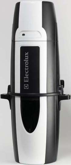
PRODUCT DIMENSIONS
please contact your local authorized dealer/distributor. Refer to page 8 - Image 1
INSTALLATION SAFETY EQUIPMENT WASTE OF ELECTRIC AND ELECTRICAL
For wall preparations and cover preparations,
EQUIPMENT (WEEE)
safety equipment such as helmet, gloves, goggles This symbol on the product or on its packaging indicates that this product
and hearing protection are recommended. may not be treated as household waste. Instead it should be handed over
to applicable collection point for the recycling of electronics and electrical
equipment. By ensuring this product is disposed of correctly, you will help
CAUTION prevent potential negative consequences for the environment and human
health, which could otherwise be caused by inappropriate waste handling
Use caution when drilling holes in walls as gas pipelines and water pipes of this product. For more detailed information about this product, please
and electrical wires may be present. contact your local waste disposal service or the shop where you purchased
the product.
If you have any questions regarding the product, spare parts, service, warranty
or anything else, please contact your local authorized dealer or distributor. INSTALLATION
GROUNDING INSTRUCTIONS Your home is most likely already fitted with the system of plastic pipes
and inlet valves and you are ready to install the central power unit. If your
This appliance must be grounded. If it should malfunction or breakdown, home is not fitted for a central vacuum system, you can contract to have
grounding provides a path of least resistance for electrical current to reduce
the Central Vacuum System installed by a professional by contacting
the risk of electrical shock. This appliance is equipped with a cord having
your local dealer or distributor or choose to do-it-yourself.
an equipment-grounding conductor and grounding plug. The plug must
be plugged into an appropriate outlet that is properly installed and The central power unit should be located as far away from the general living
grounded in accordance with all local codes and ordinances.
area as possible, yet accessible so you can remove the dirt receptacle, reach
the filter, and inspect the central power unit. A typical location would be in a
garage, where you could vacuum your car or garage area, and where emptying
WARNING the dirt receptacle and cleaning the filter would be more convenient. Other suit-
able locations are in the basement, laundry room, or ventilated storage room.
Improper connection of the equipment-grounding conductor can result in
electrical shock. Check with a qualified electrician or service person if you are
in doubt as to whether the outlet is properly grounded, or if the plug does
not fit into an outlet. Do not modify the plug provided with the appliance. CAUTION
Have a proper outlet installed by a qualified electrician.
Use caution when drilling holes in walls as gas pipelines and water pipes
This appliance is for use on a nominal 120 volt circuit and has a grounding plug and electrical wires may be present. Holes in the masonry are only
that looks like the plug illustrated in Figure A. Make sure that the appliance is allowable through it, if its standing stability is not impaired. Holes in wood
connected to an outlet having the same configuration as the plug. studs should be drilled. Depending on what material your home is
No adapter should be used with the appliance. built with, use the appropriate anchors to hang your power unit. Power unit
simply slides onto mounting bracket and clicks into place.
NOTE: In Canada, the use of a temporary adapter
is not permitted by the Canadian Electrical Code. Refer to page 8 - Image 3
• Place the central power unit in a place that is removed from the general
WARNING living area. The exhaust should be easy to connect to a ventilation pipe.
This can be done regardless of the house’s construction material.
If the supply cord is damaged, it must be replaced by a special cord • Locate the two low voltage wires near the main pipe. Remove the
available from your local authorized dealer/distributor. insulation from the low volt wire. Insert the low volt wire into the spring
loaded low volt connectors. Be certain you comply with your local
SERVICE INFORMATION electrical codes and regulations.
The instructions in this booklet serve as a guide to routine maintenance. For Refer to page 8 - Image 4
additional information, contact you’re nearest authorized dealer/distributor.
• Make sure there is a dedicated electric socket for the power unit.
RATING PLATE
• Plug in your CVS with the supplied power cord.
The type, model, and serial numbers are indicated on the rating plate
3Your power unit does not require the assembly of a muffler. Your CVS LED INDICATIONS - OPTIONAL DEPENDING ON MODEL
has the muffler installed internally. You may however desire to exhaust
the air outside. In this case you will need to attach the exhaust adapter. You machine may be equipped with some or all of the indicators listed below.
This will convert the size of the exhaust to the diameter of the central
vacuum pipe. Refer to page 8 - Image 9
Refer to page 8 - Image 5
• Place the power unit in order to make the exhaust pipe as short as
possible. Exhausts should be limited to no longer than 16.5ft (5m).
• Keep in mind that you may need space on the sides of your On/Off Motor Fault Dirt Receptacle Full Reset
central unit to be able to access the dirt receptacle.
Your power unit is equipped with a multi color LED panel. This LED
Refer to page 8 - Image 6 panel will provide you with necessary information on your power unit’s
• Align the power unit intake fitting to the main trunk line projecting from the performance, maintenance and diagnostics. Below are descriptions
wall. DO NOT GLUE. Attach the exhaust pipe to the motor exhaust if of the different messages the power unit will provide.
exhausting outdoors. Make sure the exhaust pipe is as short as possible.
NORMAL OPERATION
NOTE: Mount central power unit at least 12in (30cm) from the ceiling
and any adjacent wall, at least 27.5in (70cm) from the floor and within 6ft When the power unit is OFF and considered to be in standby mode the
(1.8m) of an electrical outlet. Review any local regulations that may apply. LED button will be RED.
Refer to page 8 - Image 2 When the power unit is ON and in use the LED will be GREEN. When
the motor fault light is ON see further description below. When the dirt
receptacle light is ON, empty dirt receptacle and press the RESET
WARNING button, and hold for 10 seconds.
Do not block the hood ventilation openings on the top of the central When you LCD power unit is in standby mode the four white lights on your
power unit. Lack of ventilation will cause the motor to overheat. LCD unit will light up in sequence and alternate moving from left to right
then reversing right to left. This pattern will repeat continuously and is an
indication that your power unit is ready for use and functioning properly.
WARNING MOTOR FAULT
Do not locate the central power unit in a high temperature area where it
is inaccessible for example, an attic or crawl space. In the case of a blown fuse or disconnected motor wire and the power
unit is not functioning the ON/OFF button will be constantly GREEN In the
For the ultimate in air control you have model ZCV920H. This model case of an over current shutdown, the ON/OFF button will be flashing RED,
features a True HEPA filter and may be included with your choice of the GREEN light will on and off rapidly and the MOTOR FAULT light will be
power unit or can be purchased from an authorized dealer/distributor. AMBER and turn on and off rapidly. This fault will reset automatically in
Simply attach the true HEPA filter as shown. 15 seconds if the low volt connection is OFF at the hose.
Refer to page 8 - Image 7 In the case of a continued over current and the low volt connection is
ON and the hose the ON/OFF button will constantly be RED, the GREEN
SYSTEM TEST light will flash slowly and the MOTOR FAULT will slowly flash AMBER.
Be certain to comply with local electrical codes and regulations. Plug In the unlikely event of a bad frequency received by the power unit the
the unit into a regular electrical outlet. You are now ready to check the power unit will not start and the ON/OFF button will remain constantly RED.
installation of the unit: In the case of a high line voltage received by the power unit the ON/OFF
button will alternate between RED and GREEN three times- pause briefly
• Be sure the filter is properly installed in the power unit.
– alternate between RED and GREEN three times – long pause- and then
• Be sure the dirt receptacle is properly secured to the power unit. repeat. This will continue until the line voltage returns to the correct level.
• Plug the hose into each inlet valve to be sure the electrical
contacts operate properly. LCD SCREEN - OPTIONAL
• Check each inlet valve for air leaks.
• Check each pipe connection for air leaks.
Refer to page 8 - Image 8
Refer to page 8 - Image 8
HOW TO USE CENTRAL VACUUM SYSTEM
ZCV920H
Your central vacuum system is controlled by a switch on your hose.
Simply insert the hose into the valve and turn the switch to the on position. In the main screen of the LCD, the Electrolux logo will appear. This logo
This will start the power unit and the flow of air. may scroll from side to side to avoid the image ingraining itself onto the
When you are finished, turn the switch on the hose to the off position LCD Display. You will see the logo when the power unit is not in use.
and remove the hose from the inlet valve. When unplugging the hose,
The button that best lines up with the Power symbol on the screen can
hold the inlet cover open for a few seconds to allow suction to decrease
be used to activate the unit. Press this button to toggle the unit on/off.
thus, protecting the inlet valve seal.
The unit may also be activated from any installed inlet.
Refer to page 8 - Image 8
4IN USE SCROLLING YOUR LCD
When not in use, you can scroll through the features of your LCD to
observe the dirt receptacle status, life monitor measure or most recent
When in use the power indicator turns green. The 4 progressive performance recorded power level.
bars will appear. A normally functioning unit should have all 4 performance
bars lit. If there are consistently less than 2 bars, you should check for the To scroll through these features simply push the button corresponding
problem. Possible issues causing the performance bars to lessen could be: with the right pointing arrow symbol.
1. Blocked suction at the hose end The next screen you will see will be the Life Meter. Scroll right further
and you will find Bucket Status. Yet another scroll will show you last
2. Clogged pipe in system
recorded performance levels of the power unit, using the Performance
3. Air restrictive tool being used, such as a crevice tool Meter on the In-Use screen. The final scroll right will show you the customer
service phone number.
4. Full dirt receptacle
5. Clogged filtration system The button lining up with the left scroll button will allow you to scroll
backwards through the screens.
EMPTY DIRT RECEPTACLE
BAG ADAPTOR
Your power unit can all be fitted with a convenient paper bag for more
convenient dirt disposal. For maintenance of the paper bag, please see
the Paper Bag Filter section, under Filter Maintenance.
Every 25 hours of use (approximately 6 months) the empty dirt receptacle
indicator will flash on the screen. This is an indication to check the dirt Refer to page 8 - Image 10
receptacle and empty it. Since this is time based, you may find the dirt
receptacle too empty or too full. If you have pets, a workshop or other UTILITY VALVE
factors that cause waste more frequently, you may wish to check the
dirt receptacle more frequently. The utility valve is similar to an Inlet valve, but is located near the power
unit. This valve is present for your convenience, as it can help clean up
Once the dirt receptacle is emptied, you push the return button to reset any dirt spilled close to the central vacuum.
the 25 hours timer. If your power supply is interrupted, or otherwise
unplugged, the empty dirt receptacle indicator will keep a memory of its OVERHEATING PROTECTION
previous status and continue life measure.
If the circuit board reaches an elevated temperature, the power unit will
To manually reset the Empty Dirt Receptacle indicator, simply press the not operate and the LED will be off or on the LCD model the screen
button lining up with the Enter symbol, and hold for 10 seconds. will be flashing. In the event of these problems, press the On/Off button,
unplug hose or wait for temperature to lower. If problems persist;
LIFE METER contact your authorized dealer or distributor.
Refer to page 8 - Image 9
The life meter has 8 bars on it. Once these bars are depleted your unit will OVERLOAD PROTECTION
continue to run, although it is strongly recommended to take it to your local
service center to be inspected and serviced. A life bar will deplete every The central vacuum system employs features that monitor the following operating
65 hours of vacuum use, meaning your central vacuum will have a long life levels: AC voltage, and current draw. If the voltage is below or above standard
of service to you. The life meter can be reset only by your service technician. operating voltage, high current draw or locked rotor, the power unit will not
If your power supply is interrupted, or otherwise unplugged, the life meter operate. In this case the On/Off button will blink until the problem ceases or on
will keep a memory of its previous status and continue life measure. the LCD model the screen will flash. If problems persist; contact your authorized
dealer or distributor. The power unit requires 30 minutes to cool down.
SERVICE INDICATOR
Refer to page 8 - Image 9
DIAGNOSTICS AND MAINTENANCE
If there is a system fault, or malfunction with your power unit, the service indicator Reduced airflow or suction indicates the central vacuum system is not
will flash. Upon seeing this symbol, we recommend that you turn the power operating at maximum efficiency. If the dirt receptacle is full and the filter
unit off, unplug the power supply for 10 seconds and then plug it back in. If the is clogged, no air can pass through the unit and no cleaning can take place.
service symbol is still on the screen, we recommend that you call for service. Instructions provided in the booklet serve as a guide to routine maintenance.
Proper airflow or suction can be maintained by keeping the dirt receptacle
This symbol may appear due to the following faults: and filter clean and the plastic tubing and hose free from clogs.
• Motor problem
EMPTYING THE DIRT RECEPTACLE
• Electronic problem
Most models feature dirt receptacles with windows to tell at a glance when
• Voltage or current problem (too high or too low)
the dirt receptacle should be emptied. In most cases, the dirt receptacle
• Power unit not responding to electronics only needs to be emptied two to three (2-3) times a year. To remove the dirt
5receptacle, press the buttons on the receptacle handles. Remove and empty CLEAR BLOCKAGE IN PIPES
the contents. Return the receptacle by attaching the bucket to the power
unit. To avoid suction loss make sure the receptacle is securely attached. Blockage in the hose
Refer to page 8 - Image 11 Plug hose into any inlet valve. If there is no suction through the hose after
connecting at a couple of inlets, the blockage is in the hose. To clear the
FILTER MAINTENANCE hose obstruction, insert a blunt instrument into the hose (garden hose,
wood dowel). You can also attempt to reverse the suction through the
The internal filter is permanent and self cleaning. However, if you have hose to dislodge the blockage.
questions about your permanent self-cleaning filter, please contact your
local authorized dealer/distributor. Refer to page 8 - Image 12 and 13
PAPER BAG FILTERS - OPTIONAL If there is one inlet valve without normal suction and you have checked
for hose blockage, then the blockage is in the pipe system between the
The volume of the paper bag is 22 liters (5 gallons). A full dust bag reduces blocked inlet valve and the power unit (see instructions below).
the systems performance. Depending on how often you use your central
vacuum system, the dust bag may need to be changed 2-3 times Insert the hose into the inlet valve where there is no suction; hold your
per year – and can be obtained at your local dealer/distributor. hand over the hose end. Release hand quickly. Repeat several times.
If blockage does not clear, contact your nearest dealer/distributor.
Instructions for changing the dust bag:
POWER UNIT WILL NOT START
1. Remove the power unit dirt receptacle.
• Check for blown fuse or circuit breaker in main house electric supply box.
2. Loosen the dust bag from the intake tube, remove and dispose.
• Unplug and check all wall inlet and low voltage connections for loose wires.
3. Place and press the new dust bag firmly into the tube.
Turn the dust bag’s opening to make it fasten firmly on the tube. • If unit still will not start, contact your nearest authorized service
station/dealer.
4. Put the dirt receptacle back on the central power unit.
POWER UNIT WILL NOT STOP
IF YOU EXPERIENCE TROUBLE WITH YOUR
CENTRAL VACUUM SYSTEM, FOLLOW THE • Check inside each inlet valve for obstruction of low-voltage contacts.
SUGGESTIONS BELOW BEFORE CALLING If no visual obstruction can be detected, disconnect the cleaner from
FOR SERVICE. the power receptacle and contact your nearest service station/dealer.
PARTIAL/TOTAL LOSS OF SUCTION POWER CENTRAL POWER UNIT SHUTS OFF BY ITSELF
• Be sure dirt receptacle is on properly. • Remove and then re-insert hose into inlet or toggle switch off-on
located on hose handle. See “Overload Protection”.
• Empty dirt receptacle.
• Remove debris from filter.
• Be sure each inlet valve is properly closed.
Instructions to install utility inlet – optional
Low voltage wire to cleaner control box Inlet valve (low voltage)
Power unit
PVC pipe Insert (length optional) Sweep 90 tee PVC pipe to system
6ELECTROLUX OXYGEN
CENTRAL VACUUM SYSTEMS LIMITED WARRANTY
ELECTROLUX CENTRAL VACUUM SYSTEMS Some States or Provinces do not allow exclusion of warranties or limitations
warrants to the original consumer purchaser that the Electrolux Oxygen of damages, so the above limitations and exclusions may not apply to
branded central vacuum power unit body and filter shall be free from defects you. This warranty gives you specific legal rights. You may have additional
in material and workmanship from the date of purchase until the original rights, which vary from State to State, or Province to Province. This limited
consumer purchaser ceases to own the system or until the system is warranty applies to USA and Canada installations only. For specific warranty
removed from its original installation, whichever occurs first. Motors information for your Country, consult your authorized Electrolux Dealer.
and electrical components in Electrolux Oxygen branded power units
are warranted for 5 years. Electrolux Quietclean branded hoses, power ELECTROLUX CENTRAL VACUUM SYSTEMS SHALL
brushes, and tools carry a 2 year warranty. This warranty does not apply NOT BE RESPONSIBLE FOR ANY CONSEQUENTIAL,
to items requiring normal replacement such as belts, bulbs, bags, etc. INCIDENTAL, OR SPECIAL DAMAGES ARISING
FROM THE USE OF THIS SYSTEM.
THIS IS THE SOLE AND EXCLUSIVE WARRANTY
OF ELECTROLUIX OXYGEN BRANDED CENTRAL Keep all payment records (bill of sale/delivery slip). The date on these
VACUUM SYSTEMS MANUFACTURED BY records establishes the warranty period. Should warranty service be
ELECTROLUX CENTRAL VACUUM SYSTEMS. required, you must show proof of purchase. If proof of purchase cannot
be supplied, the warranty period will be determined from the date of
IMPLIED WARRANTIES, INCLUDING IMPLIED manufacture of the product.
WARRANTIES OF MERCHANTABILITY OR FITNESS
FOR A PARTICULAR PURPOSE ARE LIMITED IN
DURATION OF LIMITED WARRANTY PERIOD.
Should any defect in material or workmanship appear within the time of
the above warranty, the selling dealer should be contacted. The Dealer
shall repair or replace (at Electrolux Central Vacuum System’s sole option),
or credit, such part or parts in accordance with the applicable warranty
period stated above. Electrolux Central Vacuum Systems shall not be
responsible for such service unless provided by an authorized Electrolux
Dealer utilizing authentic Electrolux replacement parts.
This warranty does not apply to loss or damage resulting from (at Electrolux
Central Vacuum System’s sole opinion) normal wear and tear, commercial
use, neglect, abuse, acts of God, accidents, improper installation, improper
modification or alteration, improper use and operation or failure to provide
proper maintenance.
71 2 3
4" (100mm) Min. 12" (30 cm)
15" (380mm)
Min. 12" Min. 12"
(30 cm) (30 cm)
4
40.5" (1032mm)
Maximum
6' (1.8 m)
19.5" (495mm) from outlet
Min. 27.5" (70 cm)
18" (465mm)
5 6 Max. 16.5' (5 m)
7
8 9 10
LCD
Screen
LED Buttons
On/Off
Motor Status
Empty Dirt Receptacle
Reset
11 12 13
8Medidas importantes de protección............................9
CONTENIDO
Información general ...................................................10 El sistema de aspiradora central viene con los siguientes componentes.
Instalación .................................................................10
Prueba del sistema ....................................................11
Modo de uso .............................................................11
Indicaciones del LED .................................................11
Pantalla LCD .............................................................11 1- Bolsa de recolección
Adaptador para bolsa ................................................12
Válvula de servicio .....................................................12
Protección contra recalentamiento ............................12 Codo adaptador de la Adaptador externo
bolsa en ángulo de 90° del tubo de escape
Protección contra sobrecarga....................................12
Diagnóstico y mantenimiento .....................................12
Mantenimiento del filtro ..............................................13
Enchufe de
Filtro de la bolsa de papel ..........................................13 entrada
Adaptador de
Resolución de problemas ..........................................13 entrada de la Soporte de pared,
bolsa
Garantía ....................................................................14 Unidad eléctrica 2 tornillos
Imágenes ..................................................................15
MEDIDAS DE PRECAUCIÓN IMPORTANTES
Al usar un aparato electrónico, siempre se deben respetar las precauciones básicas, entre las que figuran las siguientes:
LEA TODAS LAS INSTRUCCIONES ANTES DE UTILIZAR ESTE SISTEMA DE ASPIRADORA.
Esta unidad central eléctrica de aspiradora está diseñada para la extracción del polvo doméstico normal.
• No utilice extensiones o tomacorrientes con una capacidad de
ADVERTENCIA conducción de corriente inadecuada.
Para reducir el riesgo de incendio, descargas eléctricas o lesiones: • Apague todos los controles antes de desenchufar el sistema.
• No use el aparato al aire libre o en superficies húmedas. • No tire del cable para desenchufarlo. Al desenchufar, sujete el enchufe,
no el cable.
• No bloquee la cubierta del motor, las aberturas de ventilación ni el
conducto ubicado en la parte superior de la unidad eléctrica. El motor • No manipule el enchufe ni el cable con las manos húmedas.
se sobrecalentará si no tiene suficiente ventilación. • No coloque objetos en las aberturas. No utilice el sistema si las
• No instale la unidad eléctrica en áreas con temperatura elevada o poco aberturas están obstruidas; manténgalo libre de polvo, pelusas, cabello
accesibles; por ejemplo, en un ático o una cornisa. y cualquier material que pueda reducir el flujo de aire.
• Instale la unidad eléctrica a un mínimo de 12" (30 cm) del techo o de • Esta aspiradora emplea succión. Mantenga el cabello, las prendas
paredes adyacentes y por lo menos a 27,5" (70 cm) del piso. Además, sueltas, los dedos, y cualquier parte del cuerpo alejados de las
consulte los códigos y leyes locales que puedan aplicar. aberturas y piezas móviles.
• No permita que se utilice como un juguete. Se requiere de especial • No aspire ningún material que esté encendido o que despida humo,
atención en caso de ser utilizado por o cerca de los niños. como cigarrillos, fósforos o cenizas calientes.
• Este electrodoméstico no fue diseñado para ser utilizado por personas • Sea muy cuidadoso al limpiar sobre escaleras.
(incluyendo niños) con capacidades físicas, sensoriales o mentales • No aspire líquidos inflamables o combustibles, como gasolina, ni
reducidas, o sin la experiencia y el conocimiento necesarios, a menos utilice la aspiradora en áreas donde dichos elementos puedan estar
que hayan sido instruidos sobre su uso o estén bajo la supervisión de presentes.
una persona responsable de su seguridad.
• Mantenga el área de trabajo bien iluminada.
• Utilice el sistema solamente según lo indicado en este manual. Utilice
solamente los accesorios recomendados por el fabricante. • Desenchufe los electrodomésticos antes de aspirarlos.
• No utilice el sistema si el cable o el enchufe están dañados. Si la • Si el cordón eléctrico proporcionado está dañado, debe ser
aspiradora no funciona como debe, se ha dejado caer, está dañada, se reemplazado con un cordón eléctrico especial disponible de su
deja al aire libre o se sumerge en agua, devuélvala al centro de servicio. distribuidor autorizado local
• Conecte el aparato solamente a un tomacorriente debidamente puesto • No utilice el sistema si la bolsa para polvo y/o el filtro no están en su
a tierra (consulte las instrucciones de conexión a tierra). lugar.
CONSERVE ESTAS INSTRUCCIONES
9INFORMACIÓN GENERAL PLACA DE INFORMACIÓN
El tipo, el modelo y el número de serie están escritos en la placa de
El sistema de aspiradora central está diseñado para aspirar polvo y suciedad
información ubicada en el panel de control o en la cubierta del motor. Para
seca. Evite aspirar objetos duros o afilados para evitar obstrucciones o
obtener información completa de servicio de manera rápida, utilice estos
daños en la manguera y las tuberías de plástico.
números cuando busque obtener servicio.
Este manual cubre los pasos finales de instalación de la unidad eléctrica en
su hogar. También le ofrecerá información necesaria para el mantenimiento
y la resolución de problemas, en el caso improbable de que lo necesite. Si
desea obtener más información sobre la instalación o tiene preguntas acerca ADVERTENCIA
del producto, póngase en contacto con su proveedor/distribuidor autorizado
local. Hacer caso omiso de las instrucciones de seguridad puede ocasionar daños
físicos.
EQUIPO DE SEGURIDAD PARA LA
DIMENSIONES DEL PRODUCTO
INSTALACIÓN
Consulte la página 15, imagen 1
En el momento de preparar la pared o cubierta, se
recomienda usar un casco, guantes, lentes de seguridad
y protección auditiva.
DESECHOS DE EQUIPOS ELÉCTRICOS Y
ELECTRÓNICOS (WEEE)
Este símbolo que figura en el producto o su embalaje indica que el producto
PRECAUCIÓN no debe tratarse como un desecho doméstico. En lugar de eso, debe
llevarse a una planta de recolección para el reciclaje de equipos eléctricos y
Tenga precaución cuando taladre agujeros en paredes, ya que pueden electrónicos adecuada. Al asegurarse de que este producto sea desechado
haber tuberías de gas y de agua y cables eléctricos. correctamente, ayudará a evitar posibles consecuencias negativas para
Si tiene cualquier pregunta sobre el producto, piezas de repuesto, servicio, el ambiente y la salud de la población, lo que podría producirse como
garantía o sobre cualquier otro tema, póngase en contacto con su resultado del manejo inadecuado de este producto. Para obtener más
distribuidor autorizado local. información sobre este producto, póngase en contacto con el servicio local
de basura o la tienda donde adquirió el producto.
INSTRUCCIONES DE CONEXIÓN A TIERRA
INSTALACIÓN
Este electrodoméstico debe ser conectado a tierra. Si el mismo falla o
se daña, la conexión a tierra ofrece un trayecto de menor resistencia Lo más probable es que su hogar ya incluya un sistema de tuberías
para la corriente eléctrica que reduce el riesgo de electrocución. Este plásticas y válvulas de admisión y que ya esté listo para instalar la unidad
electrodoméstico está equipado con un cordón eléctrico con conductor eléctrica central. Si su hogar no tiene un sistema de aspiradora central,
de puesta a tierra y un enchufe con conexión a tierra. El enchufe debe ser puede contratar a un profesional para que instale el sistema poniéndose
conectado a un tomacorriente adecuado con conexión a tierra instalado en contacto con su distribuidor local. También puede decidir realizar la
correctamente y puesto a tierra según los códigos y leyes locales. instalación usted mismo.
La unidad eléctrica central debe ser ubicada lo más alejada posible de las
áreas de estar a la vez que quede accesible para remover el contenedor
ADVERTENCIA de polvo, acceder al filtro e inspeccionar la unidad eléctrica central. Una
ubicación típica para el sistema es el garaje, donde puede aspirar su auto
Una mala conexión del conductor de puesta a tierra puede causar o área del garaje y donde puede vaciar el contenedor de polvo y limpiar el
descargas eléctricas. Consulte a un electricista calificado o personal de filtro con mayor facilidad. Otros lugares adecuados pueden ser el sótano, la
servicio si no está seguro de que el tomacorrientes esté debidamente lavandería o un área de almacenamiento con ventilación.
conectado a tierra o si el enchufe no calza en el tomacorrientes. No
modifique el enchufe que viene con el electrodoméstico.
Pídale a un electricista calificado que instale un tomacorrientes adecuado.
Este electrodoméstico fue diseñado para ser utilizado en un circuito de PRECAUCIÓN
120 voltios y tiene un enchufe con puesta a tierra que se ve como el
Tenga precaución cuando taladre agujeros en paredes, ya que pueden
ilustrado en la Figura A. Asegúrese de que el electrodoméstico esté
haber tuberías de gas y de agua y cables eléctricos. Sólo se permite hacer
conectado a un enchufe que tenga la misma
CAJA DE TOMACORRIENTES agujeros en concreto si no se reduce su estabilidad. Los agujeros en la
configuración que el enchufe. No se debe usar un CON PUESTA A TIERRA
madera deben ser taladrados. Dependiendo del material de fabricación
adaptador con el electrodoméstico.
de su hogar, use los anclajes adecuados para instalar la unidad eléctrica.
NOTA: En Canadá, el uso de un adaptador temporal La unidad eléctrica se desliza fácilmente sobre el soporte de instalación y
LA CLAVIJA DE PUESTA A
está prohibido por el Código Canadiense de TIERRA ES LA MÁS LARGA
DE LAS TRES
encaja en su lugar.
Electricidad. FIGURA A Consulte la página 15, imagen 3
• Coloque la unidad eléctrica central en un lugar alejado de áreas de estar.
El tubo de escape se conecta fácilmente a un tubo de ventilación. Esto
ADVERTENCIA puede hacerse sin importar el material de fabricación de la vivienda.
• Ubique los dos cables de baja tensión que están cerca de la tubería
Si el cable de suministro eléctrico está dañado, reemplácelo con un cable
principal. Remueva el aislamiento del cable de baja tensión. Introduzca
especial proporcionado por su proveedor/distribuidor autorizado local.
el cable de baja tensión en los conectores de resorte de baja tensión.
Asegúrese de cumplir con las normas y leyes eléctricas locales.
INFORMACIÓN DE MANTENIMIENTO
Consulte la página 15, imagen 4
Las instrucciones proporcionadas en este manual sirven como guía para
realizar mantenimiento de rutina. Para obtener información adicional, • Asegúrese de que la unidad eléctrica tenga un tomacorriente exclusivo.
póngase en contacto con el distribuidor autorizado más cercano. • Enchufe el sistema de aspiradora central (SAC) con el cable de suministro
provisto.
10La unidad eléctrica no requiere el ensamblaje de un silenciador. El SAC tiene INDICACIONES DEL LED; OPCIONAL SEGÚN EL MODELO
un silenciador interno. Tal vez desee expulsar el aire hacia el exterior. En este
caso, deberá conectar el adaptador del tubo de escape. Esto convertirá el Su máquina puede estar equipada con todos o algunos de los indicadores
tamaño del tubo de escape al diámetro del tubo de la aspiradora central. que se muestran a continuación.
Consulte la página 15, imagen 5
Consulte la página 15, imagen 9
• Coloque la unidad eléctrica de manera tal que el tubo de escape quede lo
más corto posible. El tubo de escape no debe ser mayor de 16,5 pies (5 m).
• Recuerde que es posible que necesite espacio a ambos lados de la
unidad central para acceder al contenedor de polvo. Encendido/Apagado Falla del Contenedor de Restablecer
(On/Off) motor polvo lleno
Consulte la página 15, imagen 6
• Alinee el accesorio de admisión de la unidad eléctrica con la línea principal
La unidad eléctrica está equipada con un panel LED multicolor. Este
que sale desde la pared. NO USE PEGAMENTO. Conecte el panel LED le ofrecerá la información necesaria sobre el rendimiento,
tubo de escape al escape del motor si desea expulsar el aire al exterior. mantenimiento y diagnóstico de la unidad eléctrica. A continuación
Asegúrese de que el tubo de escape quede lo más corto posible. encontrará la descripción de los diferentes mensajes de la unidad eléctrica.
NOTA: Instale la unidad eléctrica central por lo menos a 12 pulgadas
(30 cm) del techo y de cualquier pared adyacente, por lo menos FUNCIONAMIENTO NORMAL
27,5 pulgadas (70 cm) del piso y a menos de 6 pies (1,8 m) de un Cuando la unidad eléctrica está APAGADA (OFF) y en modo de espera el
tomacorrientes eléctrico. Revise las normas locales que apliquen. botón LED está en ROJO.
Consulte la página 15, imagen 2 Cuando la unidad eléctrica está ENCENDIDA (ON) y en uso, el botón
LED está en VERDE. Cuando la luz que indica una falla del motor esté
ENCENDIDA (ON), consulte la siguiente descripción. Cuando la luz de
ADVERTENCIA contenedor de polvo lleno esté ENCENDIDA, vacíe el contenedor de polvo y
oprima el botón de restablecer durante 10 segundos.
No bloquee las aberturas de ventilación de la cubierta en la parte superior de Cuando la unidad eléctrica esté en modo de espera, las cuatro luces
la unidad eléctrica central. El motor se sobrecalentará si no tiene suficiente blancas de la pantalla LCD se iluminarán secuencialmente y alternarán el
ventilación. movimiento de izquierda a derecha y viceversa. Este patrón se repetirá de
manera continua y es indicativo de que la unidad eléctrica está funcionando
ADVERTENCIA adecuadamente y está lista para ser usada.
No instale la unidad eléctrica central en áreas con temperatura elevada o FALLA DEL MOTOR
poco accesibles; por ejemplo, un ático o una cornisa. Si se quema un fusible o se desconecta un cable del motor y la unidad
Para una experiencia máxima de control de aire, puede usar el modelo eléctrica no funciona, el botón de encendido/apagado permanecerá
ZCV920H. Este modelo cuenta con un filtro HEPA y puede venir incluido en VERDE. En caso de una interrupción por sobrecarga eléctrica, el
con su unidad eléctrica de preferencia o puede adquirirlo de un distribuidor botón ON/OFF destellará en color ROJO, la luz VERDE se encenderá y
autorizado. Simplemente coloque el filtro HEPA tal como se indica. apagará rápidamente y la luz de FALLA DE MOTOR se encenderá de
color AMARILLO y destellará rápidamente. Este falla se restablecerá
Consulte la página 15, imagen 7 automáticamente después de 15 segundos si la conexión de baja tensión
está APAGADA (OFF) en la manguera.
PRUEBA DEL SISTEMA
En caso de que haya una sobrecarga continua y que la conexión de baja
Asegúrese de cumplir con los códigos y reglamentaciones eléctricos locales. tensión esté ENCENDIDA (ON) en la manguera, la luz ROJA del botón de
Conecte la unidad a un tomacorriente normal. Ahora puede verificar la ENCENDIDO/APAGADO (ON/OFF) estará constantemente encendida y la
instalación de la unidad: luz VERDE destellará lentamente, al igual que la luz ÁMBAR de FALLA DEL
• Asegúrese de que el filtro esté correctamente instalado en la unidad MOTOR.
eléctrica. En el caso improbable de que la unidad eléctrica reciba una corriente de
• Asegúrese de que el contenedor de polvo esté correctamente asegurado frecuencia inadecuada, la unidad no se encenderá y el botón de encendido/
a la unidad eléctrica. apagado permanecerá de color ROJO. En el caso de recibir una tensión alta,
el botón de encendido/apagado de la unidad eléctrica destellará entre ROJO
• Conecte la manguera a cada una de las válvulas de entrada para y VERDE tres veces, se apagará brevemente, destellará nuevamente entre
asegurarse de que los contactos eléctricos funcionen correctamente. ROJO y VERDE tres veces, se apagará por un período más largo y repetirá el
• Inspeccione las válvulas de entrada para descartar pérdidas de aire. proceso. Esto sucederá hasta que la tensión regrese a los niveles normales.
• Inspeccione las conexiones de las tuberías para descartar pérdidas de aire.
PANTALLA LCD; OPCIONAL
Consulte la página 15, imagen 8
MODO DE USO DEL SISTEMA DE ASPIRACIÓN
CENTRALIZADA
El sistema de aspiradora central se controla mediante un interruptor en Consulte la página 15, imagen 8
la manguera. Simplemente inserte la manguera en la válvula y coloque el
interruptor en la posición de encendido. Esto encenderá la unidad eléctrica ZCV920H
y el flujo de aire. El logo de Electrolux aparecerá en la pantalla principal de la pantalla LCD.
Al finalizar, coloque el interruptor de la manguera en la posición de apagado Este logo puede desplazarse de lado a lado para evitar que la imagen quede
y retire la manguera de la válvula de entrada. Al desconectar la manguera, grabada en la pantalla LCD. El logo estará visible cuando la unidad eléctrica
mantenga la cubierta de entrada abierta durante unos segundos hasta no esté en uso.
que la succión disminuya; de este modo protegerá la junta de la válvula de El botón mejor alineado con el símbolo de Energía de la pantalla se puede
entrada. usar para encender la unidad. Pulse este botón para apagar o encender la
Consulte la página 15, imagen 8 unidad. La unidad también puede ser activada desde cualquier admisión
instalada.
11EN USO DESPLAZAMIENTO POR LA PANTALLA LCD
Cuando la unidad no está en uso, puede navegar por las diferentes
funciones de la pantalla LCD para observar el estado del contenedor de
Cuando esté en uso, la luz indicadora de corriente se encenderá de color polvo, el estado del medidor de vida útil o el nivel de energía registrado más
verde. Las 4 barras de progreso de rendimiento aparecerán. Una unidad recientemente.
que funcione normalmente debe mostrar las 4 barras de rendimiento. Si
Para desplazarse por estas funciones solamente tiene que pulsar el botón
con frecuencia hay menos de 2 barras, busque el problema que lo está
que corresponda con el símbolo de la flecha que apunta hacia la
causando. Las posibles causas de la reducción del rendimiento pueden ser:
derecha.
1. Succión obstruida en el extremo de la manguera
La próxima pantalla que aparecerá será la del medidor de vida útil.
2. Tubería del sistema tapada Desplácese más hacia la derecha y verá el estado del depósito. Desplácese
una vez más y verá los niveles de rendimiento de la unidad eléctrica
3. Uso de una herramienta que restringe el flujo de aire, como una
registrados más recientemente por medio del medidor de rendimiento que
herramienta para hendiduras
figura en la pantalla en uso. Con un último desplazamiento hacia la derecha,
4. Contenedor de polvo lleno verá el número telefónico del servicio de atención al cliente.
5. Sistema de filtración tapado Por medio del botón alineado con la flecha que apunta hacia la izquierda,
regresará a las pantallas anteriores.
LIMPIEZA DEL CONTENEDOR DE POLVO
ADAPTADOR PARA BOLSAS
La unidad eléctrica se puede usar con una práctica bolsa de papel para
una mejor eliminación de los desechos. Para obtener información sobre el
mantenimiento de la bolsa de papel, consulte la sección Filtro de la bolsa de
Cada 25 horas de uso (aproximadamente 6 meses) el indicador de limpieza papel, debajo de Mantenimiento del filtro.
del contenedor de polvo destellará en la pantalla. Esto significa que debe Consulte la página 15, imagen 10
inspeccionar el contenedor de polvo y vaciarlo. Debido a que el tiempo
está predeterminado, puede que el contenedor esté vacío o lleno. Si tiene VÁLVULA DE SERVICIO
mascotas, un taller o desempeña otras tareas que puedan generar residuos
frecuentemente, tal vez sea necesario inspeccionar el contenedor de polvo La válvula de servicio es similar a una válvula de entrada, pero está ubicada
más a menudo. cerca de la unidad eléctrica. La finalidad de esta válvula es ofrecer mayor
comodidad, de modo que pueda limpiar la suciedad cerca del sistema de
Una vez que vacíe el contenedor, oprima el botón de restablecer para aspiradora central.
reiniciar el contador de 25 horas. Si se interrumpe el suministro eléctrico o
se desenchufa la unidad, el indicador de limpieza del contenedor guardará el
PROTECCIÓN CONTRA RECALENTAMIENTO
estado actual en su memoria.
Si el tablero de circuito alcanza una temperatura elevada, la unidad de
Para restablecer el indicador de limpieza del contenedor de polvo,
potencia no funcionará y el LED se apagará o, en el caso del modelo que
simplemente oprima el botón alineado con el símbolo de Intro por
viene con pantalla LCD, la pantalla destellará. Si esto ocurre, pulse el botón
10 segundos.
de encendido/apagado (On/Off), desenchufe la manguera o espere a que la
temperatura disminuya. Si el problema persiste, póngase en contacto con
MEDIDOR DE VIDA ÚTIL su proveedor o distribuidor autorizado.
Consulte la página 15, imagen 9
El medidor de vida útil tiene 8 barras. Una vez que estas barras se hayan PROTECCIÓN CONTRA SOBRECARGA
agotado, la unidad seguirá funcionando, aunque se recomienda llevarlo
El sistema de aspiración centralizada tiene funciones para supervisar los
al centro de servicio local para ser inspeccionado y reparado. La barra de
siguientes niveles operativos: la tensión de CA y el consumo de electricidad.
vida útil se agotará cada 65 horas de uso de la aspiradora, lo que significa
Si la tensión es inferior o superior a la tensión operativa normal, se consume
que la aspiradora central tendrá una larga vida útil. El medidor de vida útil
mucha electricidad o el rotor está bloqueado, la unidad de potencia no
sólo puede ser restablecido por el técnico de servicio. Si se interrumpe
funcionará. En ese caso, el botón de Encendido/Apagado (On/Off) destellará
el suministro eléctrico o se desenchufa la unidad, el medidor de vida útil
hasta que el problema se solucione (en el caso del modelo que viene con
guardará el estado actual en su memoria.
pantalla LCD será la pantalla la que destellará). Si el problema persiste,
póngase en contacto con su proveedor o distribuidor autorizado. La unidad
INDICADOR DE MANTENIMIENTO eléctrica tarda 30 minutos en enfriarse.
Consulte la página 15, imagen 9
DIAGNÓSTICO Y MANTENIMIENTO
El flujo o la succión de aire reducidos indican que el sistema de aspiración
Si ocurre una falla del sistema o una falla de la unidad eléctrica, el indicador de
centralizada no está operando al máximo nivel. Si el contenedor de polvo
servicio destellará. Después de ver el símbolo, le recomendamos que apague
está lleno y el filtro está tapado, el aire no puede circular por la unidad, con
la unidad eléctrica, desenchufe el suministro eléctrico por 10 segundos y
lo cual no puede realizar la limpieza. Las instrucciones que figuran en este
luego vuelva a enchufarlo Si el símbolo de mantenimiento sigue encendido,
folleto sirven como guía para el mantenimiento de rutina. El flujo o la succión
recomendamos ponerse en contacto con el servicio técnico.
de aire adecuados se logran al mantener el contenedor de polvo y el filtro
Este símbolo puede aparecer debido a las siguientes causas: limpios y las tuberías de plástico y la manguera libres de obstrucciones.
• Problemas en el motor
• Problema electrónico
• Problemas de tensión o corriente (muy alta o muy baja)
• Respuesta nula por parte de componentes electrónicos de la unidad
eléctrica
12LIMPIEZA DEL CONTENEDOR DE POLVO RETIRE LAS OBSTRUCCIONES DE LOS TUBOS
La mayoría de los modelos vienen con contenedores de polvo con rendijas Obstrucción de la manguera
para que sea posible ver si necesitan vaciarse. En la mayoría de los casos,
Conecte la manguera a cualquier válvula de entrada. Si la manguera no
el contenedor de polvo solamente necesita vaciarse dos o tres (2 o 3) veces
succiona pese a haberla conectado a diversas entradas, la manguera está
al año. Para extraer el contenedor de polvo, pulse los botones que están en
obstruida. Introduzca un elemento sin filo en la manguera para limpiarla
las manijas del contenedor. Retire y deseche el contenido. Vuelva a colocar
(como una manguera de jardín o una espiga de madera). También puede
el contenedor; para ello, fije el depósito a la unidad eléctrica. Para evitar que
intentar revertir la succión a través de la manguera para destaparla.
la potencia de succión disminuya, asegúrese de que el contenedor esté
firme en su lugar. Consulte la página 15, imágenes 12 y 13
Consulte la página 15, imagen 11 Si solamente una de las válvulas de entrada tiene problemas de succión y
la manguera no está obstruida, la obstrucción está en el sistema de tubos
MANTENIMIENTO DEL FILTRO entre la válvula de entrada bloqueada y la unidad eléctrica (consulte las
instrucciones a continuación).
El filtro interno es permanente y se limpia automáticamente. Sin embargo,
si tiene alguna pregunta acerca del filtro, póngase en contacto con su Introduzca la manguera en la válvula de entrada que no succiona y tape
proveedor/distribuidor autorizado local. el extremo de la manguera con la otra mano. Quite la mano rápidamente.
Repita la operación varias veces.
Si la obstrucción no desaparece, póngase en contacto con su proveedor/
FILTROS DE BOLSA DE PAPEL; OPCIONAL
distribuidor local más cercano.
El volumen de la bolsa de papel es de 22 litros (5 galones). Una bolsa
llena de polvo disminuye el rendimiento del sistema. Dependiendo de la LA UNIDAD ELÉCTRICA NO SE ENCIENDE
frecuencia con la que use el sistema de aspiradora central, deberá cambiar
la bolsa para polvo entre 2 y 3 veces por año. Puede adquirirla de su • Verifique que no haya un fusible o un disyuntor quemado o en la caja
proveedor/distribuidor local. principal de suministro eléctrico de su casa.
Instrucciones de reemplazo de la bolsa para polvo: • Desenchufe e inspeccione todas las entradas de pared y las conexiones
de baja tensión por si hubiese cables sueltos.
1. Extraiga el contenedor de polvo de la unidad eléctrica.
• Si la unidad no se enciende, póngase en contacto con su distribuidor o
2. Afloje la bolsa para polvo del tubo de entrada, extráigala y deséchela. estación de servicio autorizado.
3. Instale y presione la bolsa nueva en el tubo con firmeza.
Gire la abertura de la bolsa para polvo y ajústela firmemente al tubo. LA UNIDAD ELÉCTRICA NO SE APAGA
4. Vuelva a colocar el contenedor de polvo en la unidad eléctrica centralizada. • Inspeccione el interior de cada válvula de entrada por si hubiese
obstrucciones en los contactos de baja tensión.
SI TIENE PROBLEMAS CON EL SISTEMA DE Si no detecta ningún tipo de obstrucción, desconecte la aspiradora del
tomacorriente y póngase en contacto con su proveedor/distribuidor
ASPIRADORA CENTRAL, SIGA LAS RECOMENDACIONES
autorizado local más cercano.
A CONTINUACIÓN ANTES DE PONERSE EN CONTACTO
CON EL SERVICIO TÉCNICO. LA UNIDAD ELÉCTRICA CENTRAL SE APAGA SOLA
• Quite e instale nuevamente la manguera en la entrada o encienda y
PÉRDIDA TOTAL/PARCIAL DE LA POTENCIA DE
apague el interruptor de la manija de la manguera. Consulte la sección
SUCCIÓN “Protección contra sobrecarga”.
• Asegúrese de que el contenedor de polvo esté instalado correctamente.
• Vacíe el contenedor de polvo.
• Retire la basura del filtro.
• Asegúrese de que cada válvula de entrada esté correctamente cerrada.
Instrucciones para instalar una admisión (opcional)
Cable de baja tensión a la caja de control de limpieza Válvula de admisión
(baja tensión)
Unidad eléctrica
Inserto de tubo PVC Accesorio en "T" de 90º Tubería PVC al sistema
(longitud opcional)
13Vous pouvez aussi lire