Pressure Cleaner Booster Pump - Installation and Operation Manual
←
→
Transcription du contenu de la page
Si votre navigateur ne rend pas la page correctement, lisez s'il vous plaît le contenu de la page ci-dessous
ENGLISH |          FRANÇAIS

                 Pressure Cleaner
                 Booster Pump
                 Installation and
                 Operation Manual

                For Polaris PB4-60 Booster Pumps with Serial Numbers beginning with "PB"
                and a manufacturing date on or after Dec 1, 2011.

                                                                  WARNING
                FOR YOUR SAFETY - This product must be installed and serviced by a contractor who is licensed and qualified
                in pool equipment by the jurisdiction in which the product will be installed, where such state or local requirements
                exist. In the event no such state or local requirement exists, the maintainer must be a professional with sufficient
                experience in pool equipment installation and maintenance, so that all of the instructions in this manual can be
                followed exactly. Improper installation and/or operation can create dangerous electrical hazards, which can cause
                high voltages to run through the electrical system. Before installing this product, read and follow all warning
                notices and instructions that accompany this product. Failure to follow warning notices and instructions may result
                in property damage, personal injury, or death. Improper installation and/or operation will void the warranty.

                If these instructions are not followed exactly, a fire or explosion may result, causing property damage, personal
                injury, or death.
H0344400 REVD

                                ATTENTION INSTALLER: This manual contains important information about the installation,
                                operation and safe use of this product. This information should be given to the owner/operator of
                                this equipment.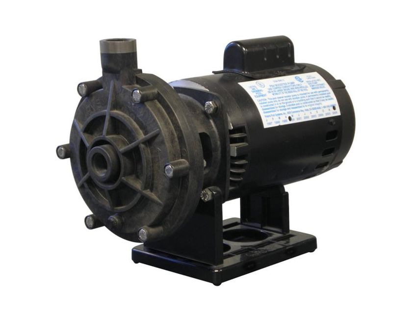
Page 2                      ENGLISH                       Polaris® PB4-60 Booster Pump | Installation and Operation Manual

                                                              Table of Contents
Section 1. IMPORTANT SAFETY INSTRUC-                                               Section 4. Operation........................................ 10
           TIONS.............................................. 3                   4.1    Start-up.............................................................. 10
1.1   Safety Instructions............................................. 3
                                                                                   Section 5. Maintenance................................... 11
1.2   Pool Pump Suction Entrapment
                                                                                   5.1    Winterizing the Pump......................................... 11
      Prevention Guidelines........................................ 5
                                                                                   Section 6. Troubleshooting and Repair......... 12
Section 2. General Description....................... 6
                                                                                   6.1    Troubleshooting................................................. 12
2.1   Introduction........................................................ 6
                                                                                   6.2    Service Technician Maintenance....................... 13
2.2   Description......................................................... 6
                                                                                          6.2.1 Blocked Impeller..................................... 13
2.3   Preparation........................................................ 6
                                                                                          6.2.2 Impeller Removal.................................... 13
Section 3. Installation...................................... 6                           6.2.3 Impeller Replacement............................. 14
3.1   Electrical Installation.......................................... 6                 6.2.4 Mechanical Seal Replacement............... 14
      3.1.1 Voltage Checks ...................................... 6                       6.2.5 Motor Replacement ............................... 15
      3.1.2 Bonding and Grounding.......................... 6
                                                                                   Section 7. Product Specifications and Techni-
3.2   Electrical............................................................ 6                cal Data........................................... 16
      3.2.1 Electrical Wiring...................................... 7              7.1    Replacement Parts List...................................... 16
3.3   Plumbing............................................................ 7       7.2    Polaris PB4-60 Booster Pump Exploded View.. 16
      3.3.1 Requirements......................................... 7
                                                                                   7.3    Pump Dimensions.............................................. 17
      3.3.2 Pipe Sizing.............................................. 8
                                                                                   7.4    Visual Identification of the New Polaris PB4-60
      3.3.3 Pump Location........................................ 8
                                                                                          Booster Pump.................................................... 18
      3.3.4 Install the Pump...................................... 9
      3.3.5 Installation Recommendations............... 9
      3.3.6 Check the Water Flow............................ 9
      3.3.7 Conduct Pressure Test........................... 10

                                                EQUIPMENT INFORMATION RECORD
 DATE OF INSTALLATION

 INSTALLER INFORMATION

 INITIAL PRESSURE GAUGE READING (WITH CLEAN FILTER)

 PUMP MODEL                                                                           HORSEPOWER

 NOTES: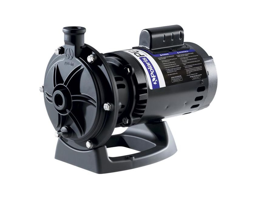
Polaris® PB4-60 Booster Pump | Installation and Operation Manual   ENGLISH            Page 3

Section 1.               IMPORTANT SAFETY INSTRUCTIONS
                   READ AND FOLLOW ALL INSTRUCTIONS
1.1     Safety Instructions
    All electrical work must be performed by a licensed electrician and conform to all national, state, and local codes.
When installing and using this electrical equipment, basic safety precautions should always be followed, including the
following:

                                                           WARNING
  To reduce the risk of injury, do not permit children to use this product.

                                                           WARNING
  To reduce the risk of property damage or injury, do not attempt to change the backwash (multiport, slide, or full
  flow) valve position with the pump running.

                                                           WARNING
  Zodiac® pumps are powered by a high voltage electric motor and must be installed by a licensed or certified
  electrician or a qualified swimming pool service technician.

                                                           WARNING
  RISK OF ELECTRIC SHOCK, FIRE, PERSONAL INJURY, OR DEATH. Connect only to a branch circuit that is
  protected by a ground-fault circuit-interrupter (GFCI). Contact a qualified electrician if you cannot verify that the
  circuit is protected by a GFCI. Make sure such a GFCI should be provided by the installer and should be tested on
  a routine basis. To test the GFCI, push the test button. The GFCI should interrupt power. Push the reset button.
  Power should be restored. If the GFCI fails to operate in this manner, the GFCI is defective. If the GFCI interrupts
  power to the pump without the test button being pushed, a ground current is flowing, indicating the possibility
  of electrical shock. Do not use the pump. Disconnect the pump and have the problem corrected by a qualified
  service representative before using.
  Due to the potential risk of fire, electric shock, or injuries to persons, Zodiac Pumps must be installed in
  accordance with the National Electrical Code® (NEC®), all local electrical and safety codes, and the Occupational
  Safety and Health Act (OSHA®). Copies of the NEC may be ordered from the National Fire Protection Association®
  (NFPA®) online at www.nfpa.org or call 617-770-3000, or contact your local government inspection agency.

                                                           WARNING
  Incorrectly installed equipment may fail, causing severe injury or property damage.

                                                           WARNING
  • Do not connect the system to an unregulated city water system or other external source of pressurized water
    producing pressures greater than 35 PSI.
  • Trapped air in system can cause the filter lid to be blown off, which can result in death, serious personal injury,
    or property damage. Be sure all air is out of the system before operating.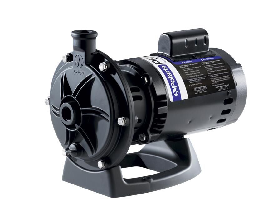
Page 4              ENGLISH              Polaris® PB4-60 Booster Pump | Installation and Operation Manual

                                                    WARNING
To minimize the risk of severe injury or death the filter and/or pump should not be subjected to the piping system
pressurization test.
Local codes may require the pool piping system to be subjected to a pressure test. These requirements are
generally not intended to apply to the pool equipment such as filters or pumps.
Zodiac® pool equipment is pressure tested at the factory.
However, if the WARNING cannot be followed and pressure testing of the piping system must include the filter
and/or pump, BE SURE TO COMPLY WITH THE FOLLOWING SAFETY INSTRUCTIONS:
• Check all clamps, bolts, lids, lock rings and system accessories to ensure they are properly installed and
  secured before testing.
• RELEASE ALL AIR in the system before testing.
• Water pressure for test must NOT EXCEED 35 PSI.
• Water temperature for test must NOT EXCEED 100°F (38°C).
• Limit test to 24 hours. After test, visually check system to be sure it is ready for operation.
NOTICE: These parameters apply to Zodiac equipment only. For non-Zodiac equipment, consult equipment
manufacturer.

                                                    WARNING
Chemical spills and fumes can weaken pool/spa equipment. Corrosion can cause filters and other equipment to
fail, resulting in severe injury or property damage. Do not store pool chemicals near your equipment.

                                                     CAUTION
Do not start pump dry! Running the pump dry for any length of time will cause severe damage and will void the
warranty.

                                                     CAUTION
This pump is for use with permanently installed pools and may also be used with hot tubs and spas if so marked.
Do not use with storable pools. A permanently installed pool is constructed in or on the ground or in a building
such that it cannot be readily disassembled for storage. A storable pool is constructed so that it may be readily
disassembled for storage and reassembled to its original integrity.

                                                     CAUTION
Do not install within an outdoor enclosure or beneath the skirt of a hot tub or portable spa. The pump requires
adequate ventilation to maintain air temperature at less than the maximum ambient temperature rating listed on
the motor rating plate.

                             SAVE THESE INSTRUCTIONS
Polaris® PB4-60 Booster Pump | Installation and Operation Manual ENGLISH Page 5
1.2 Pool Pump Suction Entrapment Prevention Guidelines
WARNING
Pump suction is hazardous and can trap and drown or disembowel bathers. Do not use or operate
swimming pools, spa, or hot tubs if a suction outlet cover is missing, broken, or loose. The following
guidelines provide information for pump installation that minimizes the risk of injury to users of pools, spas, and
hot tubs:
Entrapment Protection - The pump suction system must provide protection against the hazards of suction
entrapment.
Suction Outlet Covers - All suction outlets must have correctly installed, screw-fastened covers in place. All
suction outlet (drain) covers must be maintained. Drain covers must be listed/certified to the latest version of
ANSI®/ASME® A112.19.8 or its successor standard, ANSI/APSP-16. They must be replaced if cracked, broken, or
missing.
Number of Suction Outlets Per Pump - Provide at least two (2) hydraulically-balanced main drains, with covers,
as suction outlets for each circulating pump suction line. The centers of the main drains (suction outlets) on any
one (1) suction line must be at least three (3) feet apart, center to center. See Figure 1.
The system must be built to include at least two (2) suction outlets (drains) connected to the pump whenever
the pump is running. However, if two (2) main drains run into a single suction line, the single suction line may be
equipped with a valve that will shut off both main drains from the pump. The system shall be constructed such that
it shall not allow for separate or independent shutoff or isolation of each drain. See Figure 1.
More than one (1) pump can be connected to a single suction line as long as the requirements above are met.
Water Velocity - The maximum water velocity through the suction fitting or cover for any suction outlet must be
1.5 feet per second unless the outlet complies with the latest version of ANSI/ASME A112.19.8 or its successor
standard, ANSI/APSP-16, the standard for Suction Fittings For Use in Swimming Pools, Wading Pools, Spas, and
Hot Tubs. In any case, do not exceed the suction fitting’s maximum designed flow rate.
If 100% of the pump’s flow comes from the main drain system, the maximum water velocity in the pump suction
hydraulic system must be six (6) feet per second or less, even if one (1) main drain (suction outlet) is completely
blocked. The flow through the remaining main drain(s) must comply with the latest version of ANSI/ASME
A112.19.8 or its successor standard, ANSI/APSP-16, the standard for Suction Fittings For Use in Swimming
Pools, Wading Pools, Spas, and Hot Tubs.
Testing and Certification - Suction outlet covers must have been tested by a nationally recognized testing
laboratory and found to comply with the latest version of ANSI/ASME A112.19.8 or its successor standard, ANSI/
APSP-16, the standard for Suction Fittings For Use in Swimming Pools, Wading Pools, Spas, and Hot Tubs.
Fittings - Fittings restrict flow; for best efficiency use fewest possible fittings (but at least two (2) suction outlets).
Avoid fittings which could cause an air trap.
Pool cleaner suction fittings must conform to applicable International Association of Plumbing and Mechanical
Officials (IAPMO®) standards.
At least
three (3) feet
Listed/certified to latest Listed/certified to latest
published version of published version of
ANSI/ASME A112.19.8 - 2007 ANSI/ASME A112.19.8 - 2007
or its successor, or its successor,
ANSI/APSP-16 ANSI/APSP-16
Anti-entrapment Anti-entrapment
Cover/Grate or Suction Cover/Grate or Suction Fitting,
Fitting, screw-fastened No valves between screw-fastened
to Main Drain Sump Tee and Main Drains to Main Drain Sump
Suction Outlet Suction Outlet
(Main Drain) (Main Drain)
Pump
Valves OK between
pump and Tee
Figure 1. Number of Suction Outlets Per PumpPage 6 ENGLISH Polaris® PB4-60 Booster Pump | Installation and Operation Manual
Section 2. General Description
CAUTION
2.1 Introduction Failure to provide data plate voltage (within 10%)
This manual contains information for the proper during operation will cause the motor to overheat
installation, operation and maintenance of the Polaris and void the warranty.
PB4-60 pump. Procedures in this manual must be
followed exactly. To obtain additional copies of this 3.1.2 Bonding and Grounding
manual contact Zodiac Pool Systems, Inc. ("Zodiac") 1. The motor frame must be grounded to a reliable
at 800.822.7933. For address information, see the back grounding point using a solid copper conductor,
cover of this manual. No. 8 AWG (8.4mm2) or larger. In Canada, No.
6 AWG (13.3mm2) or larger must be used. If the
2.2 Description pump is installed within five 5 feet (1,5 meter)
of the inside walls of the swimming pool, spa, or
The Polaris booster pump, PB4-60, supplies high hot tub, the motor frame must be bonded to all
pressure water to the Polaris pool cleaner to optimize metal parts of the swimming pool, spa, or hot tub
cleaner efficiency. The pump is not self-priming and structure and to all electrical equipment, metal
should only be used when the pool filtration pump is on. conduit, and metal piping within five (5) feet (1,5
meter) of the inside walls of the swimming pool,
CAUTION spa, or hot tub.
2. Bond the motor using the provided external lug.
Running the booster pump without a filtration pump
will damage the booster pump. Improper operation
of the booster pump will void the warranty. WARNING
To avoid the risk of property damage, severe
2.3 Preparation personal injury, and/or death, always disconnect
the power source before working on a motor or its
1. Upon receipt of the pump, check the carton for
connected load.
damage. Open the carton and check the pump for
concealed damage, such as cracks, dents or a bent
base. If damage is found, contact the shipper or WARNING
distributor where you purchased the pump.
To avoid the risk of property damage, severe
2. Inspect the contents of the carton and verify personal injury, and/or death, make sure that
that all the parts are included. See Section 7.1, the control switch or time clock is installed in an
Replacement Parts List. accessible location so that in the event of an
equipment failure or a loose plumbing fitting the
Section 3. Installation equipment can be turned off. This location must not
be in the same area as the pool pump, filter, and
3.1 Electrical Installation other equipment.
3.1.1 Voltage Checks CAUTION
The correct voltage, as specified on the pump data
The pump must be permanently connected to a
plate, is necessary for proper performance and long
dedicated electrical circuit. No other equipment,
motor life. Incorrect voltage will decrease the pump’s
lights, appliances or outlets may be connected to
ability to perform and could cause overheating, reduce
the pump circuit, with the exception of devices that
the motor life, and result in higher electric bills.
may be required to operate simultaneously with the
It is the responsibility of the electrical installer to pump, such as a chlorinating device or heater.
provide data plate operating voltage to the pump by
ensuring proper circuit sizes and wire sizes for this
specific application.
3.2 Electrical
The National Electrical Code® (NEC®, NFPA-70®)
requires all pool pump circuits be protected with a MOTOR RATING
Ground Fault Circuit-Interrupter (GFCI). Therefore, it is
also the responsibility of the electrical installer to ensure HP S.F RPM VOLTS S.F. AMPS
that the pump circuit is in compliance with this and all 3/4 1.5 3450 230/115, 60Hz, 1PH 6.4/12.8
other applicable requirements of the National Electrical
Code (NEC) and any other applicable installation codes.Polaris® PB4-60 Booster Pump | Installation and Operation Manual ENGLISH Page 7
Table 1. Maximum Wire Size and Overcurrent Protection
MAXIMUM WIRE SIZE AND MAXIMUM OVERCURRENT PROTECTION*
Distance from Sub-Panel 0-50 feet (15 meters) 50-100 feet (15-30 meters) 100-200 feet (30-60 meters)
Branch Fuse AMPs Voltage Voltage Voltage
Pump Class: CC, G, H, J, K, RK, or T
Model
230 VAC 115 VAC 208-230 VAC 115 VAC 208-230 VAC 115 VAC 208-230 VAC 115 VAC
14 AWG 12 AWG 12 AWG 10 AWG 10 AWG 10 AWG
PB4-60 15A 20A
(2.1mm2) (3.3mm2) (3.3mm2) (5.3mm2) (5.3mm2) (5.3mm2)
*Assumes three (3) copper conductors in a buried conduit and 3% maximum voltage loss in branch circuit. All National Electrical Code® (NEC®) and
local codes must be followed. Table shows minimum wire size and branch fuse recommendations for a typical installation per NEC.
3.2.1 Electrical Wiring 7. A separate time clock (in addition to the filtration
1. The pump motor must be securely and adequately system time clock) is recommended to control the
grounded using the green screw provided. Ground On/Off functions of the booster pump. A manual
before attempting to connect to an electrical power switch can also be used.
supply. Do not ground to a gas supply line. 8. If a time clock is used, set it to turn the pump
on at least a half an hour after the pool filtration
2. Wire size must be adequate to minimize voltage
pump is turned on, and turn the pump off at least
drop during the start-up and operation of the
half an hour before the filtration pump shuts off.
pump. See Table 1 for wire sizes.
Periodically check the time clock settings to make
3. Insulate all connections carefully to prevent sure they are properly synchronized.
grounding or short-circuits. Sharp edges on
terminals require extra protection. To prevent 3.3 Plumbing
wire nuts from loosening, tape them using a
suitable, listed (UL®, ETL®, CSA®) electrical CAUTION
insulating tape. For safety, and to prevent entry
of contaminants, reinstall all conduit and terminal Be careful not to overtighten any pipe fitting on the
box covers. Do not force connections into the inlet or outlet of the booster pump. Overtightening
conduit box. can cause the housing to crack.
4. To configure the internal wiring of the pump motor 3.3.1 Requirements
for the correct voltage, refer to the diagram on the
motor data plate. The Polaris Booster Pump requires a dedicated
return line. Plumb the booster pump into the system so
5. The starting current of the booster pump motor that it always receives flow from the filtration pump.
may exceed 15 amps on 115 VAC voltage line. It
is recommended that a 20 amp service breaker be To ensure proper function of the pump and the cleaner,
used for the pump connected to 115 VAC. refer to Figure 2 and adhere to the following g uidelines
6. The booster pump motor is factory wired for 230 for specific equipment.
volts, but can be wired for either 115 or 230 volts. 1. Plumb the dedicated line upstream of all air
To rewire to 115 volt, follow the instructions on inducing equipment.
the name plate located on the back of the motor or
the sizing plate on the side of the motor.
NOTE
Plumb the booster pump up-stream
Minimum of all air inducing equipment.
of 3 feet
(1 meter)
Booster
Pump
Polaris
From
LXi Heater
TM
Pool Plumbing Solar To
Options System Pool
1, 2 or 3*
Heater To
Chlorinator
Spa
Filtration Pump Pool Filter
* Refer to Figures 3 and 4
Figure 2. Typical Equipment LayoutPage 8 ENGLISH Polaris® PB4-60 Booster Pump | Installation and Operation Manual
2. If a heater is installed on the system, tap the 2. The booster pump inlet connection line should be
inlet for the booster pump into the return line at least 3/4” pipe. The Softube Quick Connect
downstream and at least three (3) feet (1 meter) fittings are designed to work with the Polaris
from the heater discharge. See Figure 2. Do not reinforced hose (part #P19) only
tap the booster pump inlet into the three-foot
(1 meter) section of heat sink pipe that comes 3. Do not tap into the top of a horizontal line.
directly out of the heater. 4. Use 90° street ells to minimize bends and loops in
3. Some solar heating systems utilize the entire water the Polaris reinforced hose.
flow when the panels are being purged of air. If the
pump is installed in a non-flow pipe during solar 3.3.3 Pump Location
panel purges, install an automatic override to shut 1. Zodiac Pool Systems, Inc. recommends installing
off the pump. the pump within one 1 foot (30 cm) above the
4. Plumb the booster pump inlet higher, upstream and water level. The pump should not be elevated
as far away as possible from a chlorinator. more than a few feet above the water level of the
pool.
3.3.2 Pipe Sizing 2. If the pump is located below water level, isolation
1. Use rigid PVC pipe with a minimum diameter valves must be installed on both the suction and
return lines to prevent back flow of pool water
of 3/4”, 1-1/2” is recommended, for the
during any routine or required servicing.
dedicated return line. Flexible PVC piping is not
recommended for the dedicated pool return line
underground as it can be damaged by expansion WARNING
and movement caused by the surge of pump
Some Safety Vacuum Release System (SVRS)
pressure. Refer to Figures 3 and 4. devices are not compatible with installation of check
valves. If the pool has an SVRS device, be sure to
confirm that it will continue to safely operate when
From Filter or Heater any check valves are installed.
3. The pump and other circulation equipment must
Option #1 be located more than 5 feet (1,5 meter) from the
Horizontal water. Choose a location that will minimize turns
To Spa Leg in the piping.
Street Ell NOTE In Canada, the pump must be located a
Ground minimum of 3.0 meters [approximately 10 feet]
Polaris
Level Reinforced from the water (CSA C22.1).
Hose
Pool Return 4. The pump must be placed on a solid foundation
To Booster that will not vibrate. To further reduce the
Pump possibility of vibration noise, bolt the pump to the
foundation.
Figure 3. Preferred Plumbing Configuration NOTE Zodiac® recommends bolting the pump directly
to the foundation.
From Filter or Heater 5. The pump foundation must have adequate drainage
to prevent the motor from getting wet. The pump
needs to be protected from the rain and sun.
Option #2
6. Proper ventilation is required for the pump to
To Spa operate normally. All motors generate heat that
must be removed by providing proper ventilation.
Option #3 7. Provide access for future service by leaving a
clear area around the pump. Allow plenty of space
Ground Level above the pump for servicing.
Leave 6" 8. If the equipment is under cover, provide adequate
Pool Return
lighting.
Figure 4. Alternate Plumbing ConfigurationPolaris® PB4-60 Booster Pump | Installation and Operation Manual ENGLISH Page 9
3.3.4 Install the Pump Connector Nut Nut Gap
1. Mount the pump using two (2) concrete expansion
anchors to ensure stability.
2. Apply four (4) to six (6) wraps of Teflon® tape
to the tapered thread of the connecter barb. See
Figure 5 (a).
CAUTION Reinforced Hose Connector Barb
Barb Face
Pipe dope should NEVER be used on barb threads.
Pipe dope will severely weaken the plastic, causing Figure 6. Tighten Connector Nut to Secure Hose
leakage and may cause the plastic to fracture. DO
NOT OVERTIGHTEN. routine or required servicing.
2. To help prevent difficulty in priming, install the
3. Thread and tighten the tapered thread of the
suction pipe without high points (above inlet of
connector barb into the pump port on the pump
pump - inverted “U”s in plumbing), which can trap
body. See Figure 5 (b).
air.
4. Trim reinforced hose to required length. Make sure
3. The piping must be well supported and not forced
cut is clean and square. Avoid unnecessary loops
together where constant stress will be experienced.
or bends in the hose.
4. Always use properly sized valves. Jandy® Pro
5. Slide connector nut onto the trimmed end of the
Series diverter valves and ball valves typically
hose with threaded end toward the cut end of the
have the best flow capabilities.
hose. See Figure 5 (c).
5. Use the fewest fittings possible. Every additional
6. Apply water to connector barb to help hose slide
fitting has the effect of moving the equipment
over barbs. Push trimmed edge of hose fully onto
farther away from the water.
the connector barb. See Figure 5 (d).
NOTE If more than 10 suction fittings are needed, the
7. Slide/Rotate the connector nut to the barb to pipe size must be increased.
engage threads correctly, do not cross thread
connector nut. Tighten the connector nut until 3.3.6 Check the Water Flow
threads are no longer visible (gap about 1/8” or
just less than the width of two dimes), or until it NOTE This pump must have minimum outlet pressure
touches the barb face. See Figure 6. of 45 psi. Lower pressure may cause an over-
current motor condition.
3.3.5 Installation Recommendations
After the system is plumbed, verify water flow to
1. If the pump is located below water level, isolation the booster pump by disconnecting the inlet supply line
valves must be installed on both sides of the pump at the booster pump and then turning on the filtration
to prevent back flow of pool water during any pump. Water should flow from the line.
If there is no water flow, check the following:
d Polaris
a Reinforced
Hose
Pump Body
b
Connector Nut
Connector Barb d Inlet
Supply
Reinforced Hose Line
c Connector Barb Expansion
1-1/2" Rigid Anchor
PVC Pipe
Dedicated return
line to pool
Figure 5. Prep and install Quick Connect barb and
connector nut Figure 7. Complete InstallationPage 10 ENGLISH Polaris® PB4-60 Booster Pump | Installation and Operation Manual
1. Verify that the installation is correct. Refer to Section 4. Operation
Figure 6.
2. Use smaller eyeball fittings in the pool return lines 4.1 Start-up
or plug a return line.
Once flow is established, the pump is ready for CAUTION
operation. Never run the booster pump without water. Running
the pump “dry” for any length of time can cause
3.3.7 Conduct Pressure Test severe damage to both the pump and motor and will
void the warranty.
WARNING
When pressure testing a system with water, air CAUTION
is often trapped in the system during the filling
Never run the booster pump without the cleaner
process. This air will compress when the system is
connected. Running the pump without the cleaner
pressurized. Should the system fail, this trapped air
connected will cause damage to the pump impeller
can propel debris at a high speed and cause injury.
and will void the warranty.
Every effort to remove trapped air must be taken,
including opening the bleed valve on the filter and
loosening the pump basket lid on the filter pump If this is a new pool installation, make sure all
while filling the pump. piping is clear of construction debris and has been
properly pressure tested. The filter should be checked
WARNING for proper installation, verifying all connections and
clamps are secure according to the manufacturer's
Trapped air in system can cause filter lid to be blown recommendations.
off, which can result in death, serious personal
injury, or property damage. Be sure all air is properly WARNING
out of system before operating. DO NOT USE
COMPRESSED AIR TO PRESSURE TEST OR To avoid risk of damage or injury, verify that all
CHECK FOR LEAKS. power is turned off before starting this procedure.
WARNING 1. Turn filtration pump ON.
2. Open the filter pressure release to relieve the
When pressure testing the system with water, it is system pressure until water comes out.
very important to make sure that the pump basket
lid on the filter pump is completely secure. 3. If the filter pump is located below the water level
of the pool, opening the filter pressure release
WARNING valve will prime the pump with water.
4. Once all the air has left the filter, close the
Do not pressure test above 35 PSI. Pressure pressure release valve.
testing must be done by a trained pool professional.
Circulation equipment that is not tested properly can 5. Turn on the power to the booster pump. Then turn
fail, which could result in severe injury or property on the booster pump.
damage. 6. The booster pump should prime. The time it takes
to prime will depend on the elevation and length of
1. Fill the system with water, using care to eliminate pipe used on the suction supply pipe. See Section
trapped air. 3.3.6 for proper elevation and pipe size.
2. Pressurize the system with water to no more than 7. If the booster pump does not prime and all the
35 PSI. instructions to this point have been followed,
check for a suction leak.
3. Close the valve to trap pressurized water in the
system.
4. Observe the system for leaks and/or pressure
decay.
5. For technical support, contact Zodiac® technical
support at 800.822.7933.Polaris® PB4-60 Booster Pump | Installation and Operation Manual ENGLISH Page 11
Section 5. Maintenance
5.1 Winterizing the Pump
CAUTION
The pump must be protected when freezing
temperatures are expected. Allowing the pump
to freeze will cause severe damage and void the
warranty.
CAUTION
Do not use antifreeze solutions in the pool,
spa, or hot tub systems! Antifreeze is highly toxic
and may damage the circulation system. The only
exception to this is Propylene Glycol. For more
information see your local pool/spa supply store or
contact a qualified swimming pool service company.
1. Drain all water from the pump, system equipment,
and piping.
2. Remove the drain plug. Store the drain plug in a
safe location and reinstall it when the cold weather
season is over. Do not lose the o-ring. (Drain Plug
with O-ring Set, R0537000).
3. Keep the motor covered and dry.
NOTE Covering the pump with plastic will create
condensation, and this moisture will damage
the pump. The best way to protect your pump
is to have a qualified service technician or
electrician properly disconnect the electrical
wiring at the switch or junction box. Once the
power is removed, the two (2) quick connect
fittings can be loosened and the pump stored
indoors. For safety, and to prevent entry of
contaminants, reinstall all conduit and terminal
box covers.
4. When the system is reopened for operation, make
sure all piping, valves, wiring, and equipment
are in accordance with the manufacturer's
recommendations. Pay close attention to the filter
and electrical connections.
5. The pump must be primed prior to starting; refer
to Section 4.1, Start-up.Page 12 ENGLISH Polaris® PB4-60 Booster Pump | Installation and Operation Manual
Section 6. Troubleshooting and Repair
Zodiac® strongly recommends that you call a licensed and qualified service professional in to perform any repairs
on the filter/pump system. To locate an independent service company, check your local yellow pages or visit:
www.zodiacpoolsystems.com.
6.1 Troubleshooting
Symptom Possible Problem/Solution
The cleaning/circulating system is Verify that skimmer baskets, pump basket and other screens are clean. Clean as
not operating correctly. necessary.
Check filter and clean as necessary.
Check valve positions. Adjust as necessary.
NOTE Multiple pieces of equipment operating at one time (for example, waterfalls, spa
jets, and surface returns) may prevent the cleaning system from working properly.
Check the cleaning system manually to ensure that the system is adjusted according to the
manufacturer's recommendations.
Bubbles present in the filtration Air in system. Check the pool or spa water level to ensure it is at the proper level and
pump basket. that air is not being drawn into the suction piping. If the water is at normal level, turn off
the pump. Remove the lid and check for debris around the lid o-ring seat or improper
installation of the lid seal, as this either of these conditions will cause air to leak into the
system. Clean the lid o-ring and place on the lid. Hand-tighten the lid to make an air tight
seal. Do not use any tools to tighten the lid. Turn the pump back on.
Air leaks are still present. Check the suction side piping union. While the pump is running, try to tighten the union. If
this does not stop the air leak, turn off the pump. Loosen both unions and slide the pump
out of the way. Remove, clean and re-install both union o-rings on the filtration pump.
Reposition the pump next to the piping and secure the union nuts to the pump. With clean
union o-rings, hand-tightening of the unions should create a seal. If the unions still do not
seal, gently tighten with a large pair of tongue-and-groove pliers.
Do not over-tighten.
There is no air in the system, but It is possible that debris is caught in the pump impeller. The pump impeller moves the
the pressure is still low. water, and the vanes in the impeller can become blocked with debris. See Section 6.2,
Service Technician Maintenance, 6.2.1, Blocked Impeller, for more information.
There is no debris blocking the The pump impeller is showing signs of normal wear. Have a qualified service technician
impeller and the pressure is still check the impeller and replace as necessary.
low.
If the pump is part of a relatively new installation, it could be an electrical problem. Contact
a qualified service technician. Have the technician check for loose electrical connections
and check the voltage at the pump motor while it is in operation. The voltage must be within
10% of the motor's data plate rating. If the voltage is not within 10%, contact a qualified
electrician and/or the local power service provider.
Pump seal is leaking air. Have a qualified service technician replace the seal.
The pump is leaking water between This is caused by a damaged or failed mechanical seal. Replace the seal. See Section 6.2,
the motor and pump body. Service Technician Maintenance, 6.2.4, Mechanical Seal Replacement.
The pump gets hot and shuts off Ensure that there is adequate room around the motor to circulate air and keep the motor
periodically. cool. Have a qualified electrician check for loose connections and check the voltage at the
pump motor while it is in operation. The voltage must be within 10% of the motor's data
plate rating. If the voltage is not within 10%, contact a qualified electrician and/or the local
power service provider.Polaris® PB4-60 Booster Pump | Installation and Operation Manual ENGLISH Page 13
6.2 Service Technician Maintenance 3. Using a 9/16" wrench, loosen the bolts connecting
the pump volute to the motor backplate. See
WARNING Figure 8.
4. Pull the volute from the backplate. The impeller is
This pump must be serviced by a professional
connected to the motor shaft.
service technician, qualified in pool/spa installation.
The following procedures must be followed exactly. NOTE At this point you have access to the inlet and
Improper installation and/or operation can create outlet of the impeller to remove any debris.
dangerous electrical hazards, which can cause 5. Remove the motor shaft cover on the back of the
high voltages to run through the electrical system, motor by twisting the hex-head screw with a 90°
possibly causing property damage, serious injury, crescent wrench. See Figure 8. The motor shaft
or death. Improper installation and/or operation will will be exposed.
void the warranty.
6. Hold the motor shaft with a ½" wrench while
unscrewing the impeller from the motor shaft with
6.2.1 Blocked Impeller
your hand.
WARNING NOTE The impeller is a right-handed thread, therefore
turn the impeller counter-clockwise to unscrew.
While servicing the pump, switch off the circuit
breakers at the power source. Severe personal 7. Inspect the impeller for signs of rubbing and/or
injury or death may occur if the pump starts while damage.
your hand is inside the pump.
1. Turn off the pump. Switch off the circuit breaker
to the pump motor.
2. Look inside the pump for any debris. Remove any
debris found inside.
3. Switch on the circuit breaker to the pump motor.
4. Turn on the pump, and see if the problem is
solved.
Motor Body
5. If the impeller is still blocked with debris and it is
not possible to remove the debris, the pump will
need to be disassembled in order to access the inlet
and outlet of the impeller.
Backplate
6.2.2 Impeller Removal
Bolts
WARNING (Qty 6) Volute
While servicing the pump, switch off the circuit
breakers at the power source. Severe personal Figure 8. Remove the Pump Volute
injury or death may occur if the pump starts while
your hand is inside the pump.
1. Turn off the pump. Switch off the circuit breaker
to the pump motor. If you are not replacing the
motor, do not disconnect the electrical wiring.
NOTE If you are replacing the motor, Zodiac® strongly
recommends that a qualified service technician
or electrician properly disconnect the electrical
wiring at the pump motor.
2. Turn off any valves to prevent pool water from
reaching the pump. Drain the water from the pump
by loosening the unions or removing the drain
plugs.Page 14 ENGLISH Polaris® PB4-60 Booster Pump | Installation and Operation Manual
Carbon Seal Surface
Mechanical Seal
• Ceramic Face Seal • Carbon Face/ Spring
• Backplate Seal Side of Seal
• Impeller Side of the
Mechanical Seal Backplate
Figure 9. Replace the Mechanical Seal
6.2.3 Impeller Replacement Impeller
1. Press the new carbon face seal half (see Figure
9) on the motor shaft using a twisting motion. Figure 10. Backplate, Impeller and Mechanical
Make sure the carbon surface is facing toward the Seal Location
ceramic ring in the backplate.
6.2.4 Mechanical Seal Replacement
CAUTION NOTE This is a two (2) part replacement process. The
VERY IMPORTANT! Grasp the lower portion of the mechanical seal must be replaced as a set.
seal (opposite the carbon face) when installing the NOTE Refer to Figure 10 for an illustration of the
seal, or it will be damaged. location of the mechanical seal and impeller.
NOTE To assist assembly, only use water and soap
solution as a lubricant. Any other lubricant will WARNING
destroy the seal after a short period of time. Do not damage the ceramic or carbon surfaces of
NOTE Exercise great care to keep the seal and mating the seals. If surfaces are damaged, leaks will occur.
parts clean.
1. To access the mechanical seal, follow steps 1
2. While holding the motor shaft with a ½" wrench, through 6 of Section 6.2.2, Impeller Removal.
thread the impeller onto the motor shaft.
Hand-tighten the impeller until it is secure. Do not 2. Remove the carbon face seal half from the motor
overtighten. shaft. Refer to Figure 9. This is a spring-loaded
seal. Grasp the portion of the seal closest to the
3. Replace the motor shaft cover by inserting the impeller body and pull the seal off using a twisting
cover tabs into the slots and rotating the cover 90º motion.
clockwise.
3. Remove the motor from the backplate following
4. Install and tighten the screws lightly in a crossing the steps in Section 6.2.5, Motor Replacement.
“X” pattern using a 9/16" wrench, starting with
the inner (middle) four (4) then the outer (top and 4. Place the backplate o-ring side down and force the
bottom) four (4) to draw the backplate to the body ceramic seal out using a screwdriver or drift pin.
in an even manner. Once all the screws are snug, 5. Turn the backplate o-ring side up and insert the
torque in the same order to 18 ft-lbs. new ceramic seal side into the backplate. Use
5. Open the pressure release valve on the filter, and great care to press the seal in squarely with your
make sure it is clean and ready for operation. fingers. The ceramic is easily damaged and must
be pressed in using only your fingers or soft tools.
6. Switch on the circuit breaker to the pump motor. Do not use any lubricant other than water and soap
7. Turn on the pump and check the system for normal solution.
operation. 6. Install the motor following the steps in
8. Once all the air has left the filter, close the Section 6.2.5, Motor Replacement.
pressure release valve. 7. Install the backplate following the steps in
Section 6.2.3, Impeller Replacement.Polaris® PB4-60 Booster Pump | Installation and Operation Manual ENGLISH Page 15
6.2.5 Motor Replacement 6. To reassemble the pump after replacing the motor,
follow steps 1 through 9 of Section 6.2.3, Impeller
CAUTION Replacement.
To ensure continued safety and reliable operation, 7. Have a qualified service technician or electrician
Zodiac Pool Systems, Inc. requires that you replace properly connect the electrical wiring at the pump
the motor with a motor that has the identical HP motor.
rating and service factor (Zodiac Pool Systems, Inc. NOTE Zodiac Pool Systems, Inc. recommends that
approved only). the mechanical seals be replaced at the same
time the motor is replaced. See Section 6.2.4,
WARNING Mechanical Seal Replacement, for details.
To avoid the risk of property damage, severe
personal injury, or death, turn off the pump and
switch off the circuit breaker to the pump motor
before beginning this procedure.
1. Have a qualified service technician or electrician
properly disconnect the electrical wiring at the
pump motor.
2. To disassemble the pump volute from the motor,
follow steps 1 through 6 in Section 6.2.2, Impeller
Removal.
3. Remove the four (4) 9/16" screws and remove the
motor.
NOTE Before removing the backplate, note the
alignment of the backplate to the motor. Label is
facing upward. See Figure 11.
4. If installing a new motor, remove the protective
plastic cap from the motor shaft. Place the motor
on the backplate. The label should be facing
upward. The starting capacitor on the motor should
be at the 12 o'clock position.
5. Replace the four (4) bolts and washers holding the
backplate to the motor.
Impeller
Label Location
Backplate
Bolts with
Washers
(Qty 4) Motor Assembly
Figure 10. Remove Back PlatePage 16 ENGLISH Polaris® PB4-60 Booster Pump | Installation and Operation Manual
Section 7. Product Specifications and Technical Data
7.1 Replacement Parts List
To order or purchase parts for Polaris pumps, contact your nearest Zodiac® dealer. If they cannot supply you with
what you need, contact Zodiac technical support at 800.822.7933 or www.zodiacpoolsystems.com.
Key Order Part
No. Description Qty No. Comments
1 Replacement Motor for Booster Pump 1 P61
2 O-Ring, Backplate, PB4-60 1 R0536600
3 Seal, Ceramic and Spring 1 R0445500
4 Impeller, PB4-60 1 R0536400
5 Volute, PB4-60 1 R0536300 (Includes Drain Plug with O-Ring)
6 Bolts with Washers and Nuts 6 R0536900
7 Drain Plug with O-Ring, Common 1 R0537000
8 Base, Booster, PB4-60 1 R0537100
9 Bolts and Washers, Stainless, Motor, PB4-60 4 R0536800
Kit includes 1 ea 6' length of
10 Quick Connect Install Kit 1 R0617100 reinforced hose and 4 ea Quick
Connect fittings.
Comes with 4ea Quick Connect
11 Quick Connect Fittings 4 R0621000
Fittings and Installation Instructions.
12 Pump Hose 6FT Reinforced 1 P19 6' Length
13 Backplate PB4-60 1 R0536700 Includes Seal and Backplate O-ring
7.2 Polaris PB4-60 Booster Pump Exploded View
9 (Qty 4)
1
13
2
4 3
5
10
6 (Qty 6) 8
12
6 (Qty 6) 11
7
Figure 1. Polaris PB4-60 Booster Pump Exploded ViewPolaris® PB4-60 Booster Pump | Installation and Operation Manual ENGLISH Page 17
7.3 Pump Dimensions
8 13/16" 15 1/16"
22.4 cm 1 9/16" 38.3 cm
4 cm
111/2"
29.2 cm
5 /16"
13
14.8 cm
6 3/8" 4 15/16"
16.2 cm 12.5 cm
Bolt Holes, Front Edge of Union
Center to Center to Center of Bolt Holes
NOTE When installing pump, leave a minimum of 2.0 feet (60 cm) of clearance above the pump for
service.
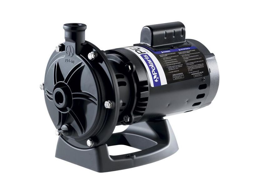
Figure 12. Polaris PB4-60 Booster Pump DimensionsPage 18 ENGLISH Polaris® PB4-60 Booster Pump | Installation and Operation Manual 7.4 Visual Identification of the New Polaris PB4-60 Booster Pump For Polaris PB4-60 Booster Pumps with Serial Numbers beginning with "PB" and a manufacturing date on or after Dec 1, 2011. Figure 13. New Polaris PB4-60 Booster Pump Older models of the PB4-60 Booster Pumps discontinued as of Nov 30, 2011. Figure 14. Discontinued Older Model of PB4-60 Booster Pump
Polaris® PB4-60 Booster Pump | Installation and Operation Manual   ENGLISH   Page 19

                                    NOTES
Zodiac Pool Systems Canada, Inc. 2115 South Service Road West, Unit 3 Oakville, ON L6L 5W2 1.888.647.4004 | www.ZodiacPoolSystems.ca Zodiac Pool Systems, Inc. 2620 Commerce Way, Vista, CA 92081 1.800.822.7933 | www.ZodiacPoolSystems.com ZODIAC ® is a registered trademark of Zodiac International, S.A.S.U., used under license. Polaris® and the Polaris 3-wheeled cleaner design are registered trademarks of Zodiac Pool Systems, Inc. All trademarks referenced herein are the property of their respective owners. ©2014 Zodiac Pool Systems, Inc. H0344400 REVD
Pompe de
                surpression pour
                nettoyeur haute
                pression
                Manuel d’installation et
                de fonctionnement

                Pour les pompes de surpression Polaris PB4-60 dont les numéros de série
                commencent par « PB », fabriquées le 1er décembre 2011 ou postérieurement.

                                                                 AVERTISSEMENT
                POUR VOTRE SÉCURITÉ – L’installation et l’entretien de ce produit doivent être effectués par un technicien autorisé et qualifié
                pour la réparation des équipements de piscine par les autorités compétentes du territoire dans lequel ledit produit est installé
                lorsque de telles exigences locales ou provinciales sont édictées. Si aucune exigence locale, provinciale ou territoriale n’est
                disponible, l’agent d’entretien doit être un professionnel avec suffisamment d’expérience dans l’installation et la maintenance
                d’équipement de piscine pour appliquer correctement les consignes du présent manuel. Une installation ou utilisation incorrecte
                peut causer de dangereux risques électriques pouvant provoquer le passage de courants haute tension dans le système
                électrique. Avant d’installer ce produit, veuillez lire et suivre toutes les consignes de mise en garde et les instructions incluses
                avec ce produit. Le non-respect des avertissements et des instructions pourrait causer des dommages matériels, des blessures
                graves ou même un décès. L’installation ou l’utilisation inappropriée annuleront la garantie.

                Si ces consignes ne sont pas suivies à la lettre, un incendie ou une explosion pourrait survenir causant des dommages
                matériels, des blessures ou un décès.

                                   À L’ATTENTION DE L’INSTALLATEUR : Le présent manuel contient des renseignements importants sur
H0344400 REVD

                                   l’installation, le fonctionnement et l’utilisation dans risque de ce produit. Ces renseignements doivent être
                                   donnés au propriétaire ou à l’utilisateur de cet appareil.
PAGE 22 FRANÇAIS Pompe de surpression Polaris® PB4-60 | Manuel d’installation et de fonctionnement
Table des matières
Section 1. Consignes de sécurité Section 4. Fonctionnement............................. 30
importantes.................................... 23 4.1 Démarrage......................................................... 30
1.1 Consignes de sécurité....................................... 23
Section 5. Entretien......................................... 31
1.2 Normes de prévention du piégeage par aspiration
de la pompe de piscine...................................... 25 5.1 Hivernage de la pompe...................................... 31
Section 2. Description générale..................... 26 Section 6. Dépannage et réparation............... 32
2.1 Introduction........................................................ 26 6.1 Dépannage........................................................ 32
2.2 Description......................................................... 26 6.2 Maintenance par un technicien
en entretien et en réparation.............................. 33
2.3 Préparation........................................................ 26
6.2.1 Turbine bloquée...................................... 33
Section 3. Installation...................................... 26 6.2.2 Retrait de la turbine ............................... 33
3.1 Installation électrique......................................... 26 6.2.3 Remplacement de la turbine................... 34
3.1.1 Vérifications de la tension....................... 26 6.2.4 Remplacement de
la garniture mécanique .......................... 34
3.1.2 Connexion et mise à la terre................... 26
6.2.5 Remplacement du moteur ..................... 35
3.2 Électrique........................................................... 26
3.2.1 Câblage électrique.................................. 26 Section 7. Caractéristiques du produit et don-
3.3 Plomberie........................................................... 27 nées techniques............................. 36
3.3.1 Exigences............................................... 27 7.1 Liste des pièces de rechange ........................... 36
3.3.2 Dimensions des tuyaux.......................... 28 7.2 Vue éclatée de la pompe de surpression Polaris
3.3.3 Emplacement de la pompe..................... 28 PB4-60............................................................... 36
3.3.4 Installer la pompe................................... 29 7.3 Dimensions des pompes................................... 37
3.3.5 Recommandations relatives 7.4 Identification visuelle de la nouvelle pompe de
à l’installation.......................................... 29 surpression Polaris PB4-60............................... 38
3.3.6 Vérifier le débit d’eau.............................. 29
3.3.7 Effectuer des tests de pression.............. 30
FICHE DE RENSEIGNEMENTS SUR L’ÉQUIPEMENT
DATE D’INSTALLATION
INFORMATION SUR L’INSTALLATEUR
LECTURE INITIALE DU MANOMÈTRE (AVEC FILTRE PROPRE)
MODÈLE DE POMPE CHEVAUX
REMARQUES :Pompe de surpression Polaris® PB4-60 | Manuel d’installation et de fonctionnement FRANÇAIS PAGE 23
Section 1. Consignes de sécurité importantes
LIRE ET SUIVRE TOUTES LES CONSIGNES
1.1 Consignes de sécurité
Tous les travaux d’électricité doivent être accomplis par un électricien agréé et doivent se conformer aux normes
fédérales, provinciales et locales. Au moment de l’installation et de l’utilisation de cet équipement électrique, des
précautions de base doivent toujours être suivies, entre autres :
AVERTISSEMENT
Pour réduire le risque de blessure, ne pas permettre aux enfants d’utiliser ce produit.
AVERTISSEMENT
Afin de réduire le risque de dommages matériels ou de blessures, ne pas essayer de changer la position du robinet de lavage
à contre-courant (multivoies, de glissement ou de passage intégral) pendant le fonctionnement de la pompe.
AVERTISSEMENT
Les pompes Zodiac® fonctionnent à l’aide d’un moteur électrique haute tension et doivent être installées par un électricien
agréé ou licencié, ou un technicien en entretien et en réparation de piscines qualifié.
AVERTISSEMENT
RISQUE DE CHOC ÉLECTRIQUE, D’INCENDIE, DE BLESSURES OU DE MORT. Brancher seulement à un circuit qui est
protégé par un disjoncteur de fuite à la terre. En cas de doute, consulter un électricien certifié. S’assurer qu’un tel disjoncteur
est fourni par l’installateur et fait l’objet d’essais régulièrement. Pour tester le disjoncteur de fuite à la terre, appuyer sur le
bouton de test. Le disjoncteur de fuite à la terre doit couper l’alimentation électrique. Appuyer sur le bouton de réinitialisation.
L’alimentation électrique devrait être restaurée. Si le disjoncteur de fuite à la terre ne fonctionne pas de cette façon, c’est qu’il
est défectueux. Si le disjoncteur de fuite à la terre coupe l’alimentation à la pompe sans que le bouton de test soit enfoncé, il y
a alors circulation de courant à la terre, ce qui indique la possibilité de choc électrique. Ne pas utiliser la pompe. Débrancher la
pompe et s’assurer que le problème soit résolu par un représentant d’entretien et de réparation qualifié avant de l’utiliser.
En raison du risque potentiel d’incendie, de choc électrique ou de blessures corporelles, les pompes Zodiac doivent être
installées conformément au Code national d’électricité (NEC®), à tous les codes locaux d‘électricité et de sécurité et à la Loi
sur la santé et la sécurité au travail (LSST). Vous pouvez obtenir des exemplaires du Code national d’électricité (NEC) de la
National Fire Protection Association® (NFPA®) en ligne à www.nfpa.org ou en composant le 617 770-3000 ou en contactant
votre organisme d’inspection gouvernemental local.
AVERTISSEMENT
Un équipement mal installé peut être défaillant et causer des blessures graves ou des dommages matériels.
AVERTISSEMENT
• Ne pas raccorder le système à un réseau urbain de distribution d’eau non règlementé ou à une autre source externe d’eau
sous pression générant des pressions supérieures à 2,4 bars (35 psi).
• L’air emprisonné dans le système peut provoquer l’ouverture par soufflage du couvercle du filtre et entraîner la mort, de graves
blessures corporelles ou des dommages matériels. Avant d’utiliser le système, s’assurer que tout l’air soit bien expulsé.PAGE 24 FRANÇAIS Pompe de surpression Polaris® PB4-60 | Manuel d’installation et de fonctionnement
AVERTISSEMENT
Afin de réduire les risques de blessures graves ou même la mort, le filtre et/ou la pompe ne devraient pas être soumis à l’essai
de pressurisation de la tuyauterie.
Les codes locaux peuvent exiger l’application d’un essai de pressurisation sur la tuyauterie de la piscine. Ces exigences ne
s’appliquent généralement pas à l’équipement de piscine, tel que les filtres ou les pompes.
L’équipement de piscine Zodiac® a fait l’objet d’essais de pressurisation en usine.
Si toutefois l’AVERTISSEMENT ne peut être respecté et que l’essai de pressurisation de la tuyauterie doit aussi inclure le filtre
ou la pompe, S’ASSURER DE SE CONFORMER AUX CONSIGNES DE SÉCURITÉ SUIVANTES :
• Vérifier que l’ensemble des brides, boulons, couvercles, bagues de retenue et accessoires du système sont correctement
installés et fixés solidement avant d’effectuer un test.
• ÉVACUER TOUT L’AIR dans le circuit avant les essais.
• La pression d’eau pour l’essai ne doit PAS DÉPASSER 35 LB/PO² (241 kPa).
• La température de l’eau pour l’essai NE DOIT PAS DÉPASSER 100 °F (38 °C).
• Limiter l’essai à 24 heures. Après l’essai, vérifier visuellement le système pour s’assurer qu’il est prêt à fonctionner.
Avis : ces paramètres s’appliquent uniquement à l’équipement Zodiac. Pour l’équipement non fabriqué par Zodiac, consulter le
fabricant.
AVERTISSEMENT
Des déversements et vapeurs chimiques peuvent affaiblir l’équipement de la piscine ou du spa. La corrosion peut causer la
défaillance des filtres et autre équipement, ce qui peut entraîner des blessures graves ou des dommages matériels. Ne pas
entreposer de produits chimiques de piscine près de votre équipement.
ATTENTION
Ne pas démarrer votre pompe à sec! Faire fonctionner la pompe à sec pendant une durée quelconque causera des dommages
importants et annulera la garantie.
ATTENTION
Cette pompe doit être utilisée avec des piscines installées de manière permanente et, si cela est également mentionné, avec
des cuves thermales et des spas. Ne pas utiliser avec des piscines remisables. Une piscine installée de manière permanente
est construite dans le sol ou sur le sol ou dans un édifice de sorte qu’elle ne peut pas être facilement démontée aux fins de
remisage. Une piscine remisable est construite pour être facilement démontée aux fins d’entreposage, puis réassemblée à son
état initial.
ATTENTION
Ne pas installer dans une enceinte extérieure ou sous les bords d’une cuve thermale ou d’un spa portatif. La pompe nécessite
une ventilation adéquate afin de maintenir la température de l’air inférieure à la température ambiante maximale indiquée sur
la plaque signalétique du moteur.
CONSERVER CES DIRECTIVESVous pouvez aussi lire