Services & Wiki Documentation - Release v0.0.1 Jubo - Read the Docs
←
→
Transcription du contenu de la page
Si votre navigateur ne rend pas la page correctement, lisez s'il vous plaît le contenu de la page ci-dessous
Services & Wiki Documentation
 Release v0.0.1

 Jubo

 Aug 26, 2019
Sommaire:

1 L’InfiniFab 3

2 Les projets de l’InfiniFab 7

3 Les Services de L’InfiniFab 73

4 Manuel pour contribuer à la documentation 77

 i
ii
Services & Wiki Documentation, Release v0.0.1

Vous trouverez ici basiquement toutes les informations concernant le projet de l’InfiniFab.
Pourquoi passer par ce format ?
L’idée en faisant quasiment QUE de la documentation, est d’avoir un moyen de vous faire participer au projet d’une
manière qui me semble la meilleure. De mon côté cela me permet d’avoir un moyen simple de mettre à jour ces
informations, et de votre côté vous pouvez apporter vos idées sans avoir besoin d’un compte utilisateur en plus (il vous
faut juste un compte sur Github).
Vous trouverez ici les indications pour participer à la documentation
Vous pouvez continuer votre visite pour connaitre tout du projet InfiniFab !!

Sommaire: 1
Services & Wiki Documentation, Release v0.0.1

2 Sommaire:
CHAPTER 1

 L’InfiniFab

Sur cette page, vous aurrez une description du projet “Infini Fab”.

1.1 L’Infini Fab, un fablab comme les autres

Avant tout l’Infini Fab a pour but d’être un fablab.

1.1.1 Qu’est-ce qu’un fablab ?

Un fablab est un lieu ouvert au public avec diverse machine et outils accessible pour permettre à une communauté
ou des bidouilleurs de passage de réaliser leur projets personnels. Aujourd’hui on peut trouver un fablab dans de
nombreuses villes en France et dans le monde, chaque lieu étant particuliers, il est difficile d’aller plus loin dans la
définition d’un fablab. D’autre lieu peuvent se rapprocher d’un fablab dans leur philosophie, qui consiste à promouvoir
le Do It Yourself (DIY), il existe par exemple des makerspaces, sensiblement identique, des hackerspaces, un peu plus
portés vers la technologie, etc.. Il s’agit là d’un bref exposé et chaque espace de ce type mériterait sa propre définition.

1.1.2 La voie choisie pour l’Infini Fab

On constate une ouverture de ce type de lieu dans de nombreuse villes, et pourtant leur existence reste inconnue d’une
majorité, leur utilisation limitée à une encore plus petite portion de la population. L’Infini Fab porte la conviction
que les lieu du type fablabs pourraient apporter des solutions vers une société plus juste envers la nature et envers
l’humain. C’est pourquoi la mission principale et la raison d’être de l’Infini Fab est de permettre au personne qui
ne se considèrent pas comme maker/bidouilleurs de pousser la porte d’un fablab pour essayer de fabriquer un objet
soit même. Pour cela l’Infini Fab choisi l’approche “produit”, c’est à dire qu’il proposera un catalogue d’objet dont la
conception a déjà été faite et dont il ne reste que la fabrication. Un accompagnement sera fait durant toute la fabrication
pour s’assurer qu’elle soit mener de façon correcte et dans les temps. L’idée est de permettre à certain de réaliser qu’il
pourrait eux aussi fabriquer leur propre objets.

 3
Services & Wiki Documentation, Release v0.0.1

1.1.3 C’est qui l’InfiniFab?

C’est le projet d’une personne, Julien Bonnaud, Ingénieur qui cherche un travail avec plus de sens et plus ammusant.
Mais j’ai eu la chance de rencontrer déjà beaucoup de personnes impliquées dans le mouvement donc j’en profites
pour remercier :
 • L’Openfab, un super fablab de Bruxelles, je les aidés au début, et fait de mon mieu à chaque séjour dans la
 capitale Belge.
 • VULCA, réseau des fablabs Européens, déjà bien implanté, je les connais depuis peu mais beaucoup de poten-
 tiels et de collaboration à venir
 • MAKEME, réseau de maker dans l’Ouest de la France, ils organisent souvent des festivals et m’ont déjà donné
 l’opportunité de présenter mon projet lors du MakeMe fest d’Angers en 2018 et lors du Nantes Maker Campus
 en 2018.

1.2 Un Fablab dans une tiny house

Si l’objectif principal de l’Infini Fab est de démocratiser les fablabs, l’objectifs est un jour d’avoir un lieu pour ac-
cueillir les apprenti makers.

1.2.1 Parce que c’est chouette

Regardez moi ces superbe tiny house

1.2.2 La tiny InfiniFab

Je sais à peu près quelles machines pourraient être présentes dans la tiny house, à savoir:
 • Une CNC
 • Une découpeuse laser
 • Une imprimante 3D
 • Une découpeuse vynil
 • Plein de petits outillage
Il faudrait pouvoir faire une bonne représentation 3D, pour ça j’ai choisi le logiciel Fusion360, qui est très puissant et
qui est gratuit. Si vous avez de l’expérience avec ce logiciel, de la même lanière qu’avec cette documentation vous
êtes les bienvenu pour participer.

1.2.3 Le chemin jusqu’à la tiny

4 Chapter 1. L’InfiniFab
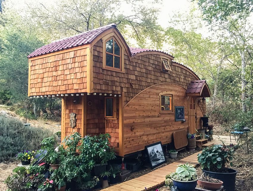
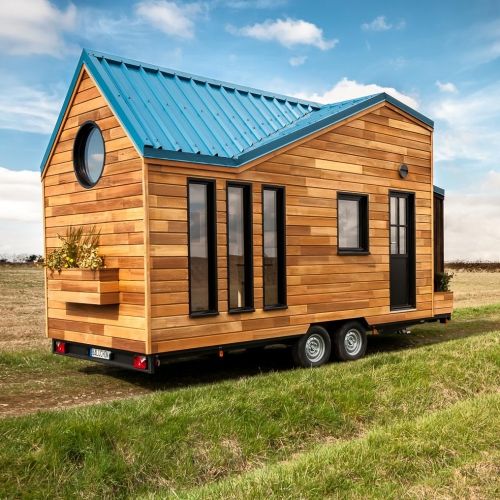
Services & Wiki Documentation, Release v0.0.1

 Fig. 1: Tiny House Essen’ciel de l’entreprise Baluchon

1.2. Un Fablab dans une tiny house 5
Services & Wiki Documentation, Release v0.0.1

 Fig. 2: Tiny House Essen’ciel de l’entreprise Baluchon

6 Chapter 1. L’InfiniFab
CHAPTER 2

 Les projets de l’InfiniFab

Sur cette page vous trouverez l’ensemble des projets en cours de l’Infini Fab, que ce soit des produits destinés à
être présent dans le catalogue de l’Infini Fab mais aussi les collaborations en cours entre l’Infini Fab et d’autre fa-
blab/makers.

2.1 Les ateliers : Le travail de modèle (template)

2.1.1 Les Fablabs/Makerspace : des espaces inaccesibles

Le nombre de fablab a augmenté de façon continue depuis un peu plus de 10 ans. On constate aujourd’hui un maillage
important du térritoire en Europe, et la possibilité de trouver un fablab à proximité de son domicile avec de nombreuse
machine=outils qui peuvent convenir à nombreux projets personnels. Néanmoins La population fréquentant ces lieux
n’a pas nécéssairement augmenté de façon proportionnelle. Celle-ci se limitant principalement aux habitués. Alors
que la vocation d’un fablab est avant tout de transmettre les connaissances, les compétences et de mettre à dispositions
des machines et des outils pour TOUT LE MONDE.

2.1.2 La documentation, le nerf de la guerre

Tout maker/bidouilleur, s’il veut permettre à un autre de réaliser le projet qu’il a conçu, doit rédiger une documentation
explicant les étapes de réalisation de tel ou tel projet. Cette problématique existe déjà depuis quelque temps dans le
monde des fablabs, on trouve divers projets en place pour permettre cette documentation. Par exemple Do Doc qui
propose un outils pour ne pas louper une seule étape de la réalisation d’un projet.
Cependant, ces documentations sont du type tutoriels ou manuel d’utilisation. Elle sont réalisées le plus souvent par
une seule personne (celle à l’origine du projet) et consultées par une seule personne (celle voulant reproduire le projet).
Dans cette situation, il n’y a souvent pas d’échange entre ces 2 parties.
L’idée ici est alors de changer la manière dont cette échange se passe. Il s’agit ici de profiter de lieux déjà existant
pour permettre la transmition ou la réalisation de projet entre un maker par forcement à l’origine de ce projet envers
un ou plusieurs néophites

 7
Services & Wiki Documentation, Release v0.0.1

2.1.3 Le modèle atelier: La transmition en direct du savoir et des compétences

Il s’organise déjà depuis plusieurs années des ateliers de découverte dans les fablabs. Ils sont le plus souvent docu-
mentés de manière informelles. L’objectifs de ce projet ici est de formaliser la documentation de ces ateliers, avec
plusieurs objectifs :
 • Le modèle de documentation ici doit être perçue comme un outils pour aider les makers à formaliser les ateliers
 qu’il pourraient tenir dans un fablab
 • Ce modèle doit être pratique, et permettre une documentation rapide, pour synthetiser toutes les informations
 nécéssaire à la bonne tenue d’un atelier
 • Ce modèle ne se substitue pas à un tutoriel ou un manuel complet d’un projet, il se focalise sur les élément
 nécéssare à la bonne tenue d’un atelier (compétence, machine, public visé, budget, ateliers passés. . . )

2.1.4 Le modèle

Le 1er modèle

Ce 1er modele à été réalisé en partenariat avec l’Openfab Le support choisi à été une feuille excel, et le résultat
exploitable est une page unique sous forme d’un tableau résumant toutes les informations nécéssaire à la bonne tenu
d’un atelier.
Le 1er modèle

Le mode d’emploi

 • Un maker considère qu’il pourrait organiser un atelier dans un fablab
 • Il duplique l’onglet “template” du document
 • Il rempli toutes les informations qu’il a à disposition concernant l’atelier qu’il souhaite organiser

Les 1er exemples

Atelier sticker
1ère soudure

La particiption à ce document

 • Alimenter la section “Meta-data”
 • Faites vos remarques sur le fond (quelles informations pertinantes manques ? quelles sont celle dont on peut se
 passer ?)
 • Faite vos remarques sur la forme (comment arranger le tableau d’une meilleure manière ?)

2.2 Les Residences / Residencies

Cette partie du wiki est en Anglais car les residences ont été réalisées à l’etranger. // All these pages are in
English because all residencies were performed outside of France.

8 Chapter 2. Les projets de l’InfiniFab
Services & Wiki Documentation, Release v0.0.1

On these pages is the documentation about the residencies performed in different fablabs around the Earth. Residencies
are of different amount of times (days or month).

2.2.1 Verona Fablab

At around 10km from Verona in Italy, at Grezzana, you’ll find in the following the documentation on all projects
performed during a residency of 2 month during summer 2019. This residency happens because of the program Inn
Veneto.

Solution via LORAWAN

The hydroponic system is inspired by Ortocity, a system that allows control and watering of the soil of a module
culture. The main inspiration come from usage of LORA technology.
In the following are annotation and investigation of the technology used. In the end, the use of LORAWAN hasn’t
been choose because WIFI.

Creation of a LORAWAN Gateway

Because the previous LORAWAN gateway used by Ortocity wasn’t available at the begining of the investigation, a
LORAWAN Gateway was created to allow Ortocity to send data.
The material used
 • A Lopy 4 board
https://docs.pycom.io/datasheets/development/lopy4/
 • The expansion board 2.0
https://docs.pycom.io/datasheets/boards/expansion2/
 • a WIFI antena
Process
The code to be uploaded on the Lypo
On recent computer, driver shall be present and pymark shall detect lypo devices and state connected at beginning,
otherwise instal driver, etc . . . of lopy material :
https://docs.pycom.io/gettingstarted/installation/
Follow the instruction which are pretty basics.
https://docs.pycom.io/tutorials/lora/lorawan-nano-gateway.html
The gateway needs to be registered on the thingnetwork(TTN). in that purpose :
 • we create a python script with the code suggested in “Gateway ID” chapter to be run once uploaded
 • retrieve the files main.py, config.py and nanogateway.py files from github, and just put local wifi ssid&password
 into config.py
 • just follow throught the instruction on registering your gateway (with gateway ID generated, and the correct
 frequency&portal from where you are)
 • Verify the good reference of the gateway on TTN platform

2.2. Les Residences / Residencies 9
Services & Wiki Documentation, Release v0.0.1

Note: The main issues come from uploading code into lypo.
You needs to upload last firmware on the device following the method: https://docs.pycom.io/gettingstarted/
installation/firmwaretool.html
during firmware update erase flash on lypo

Interface with Lypo can be done with atom IDE with pymark module installed

Note: make sure the lopy works, with the following simple program : https://docs.pycom.io/gettingstarted/
programming/first-project.html
update the firmware https://docs.pycom.io/gettingstarted/installation/firmwaretool.html
with atom and Pymark ad-on, upload lora-gate way code https://docs.pycom.io/tutorials/lora/lorawan-nano-gateway.
html
useful video : https://www.youtube.com/watch?v=d7CHfmqkVWc

Create Lora device, node

 Warning: This can be used to test the LORAWAN gateway when Ortocity isn’t available.
 NOT USED IN HYDRO PROJECT

Material:
 • 1 Lopy 1 from pycom
https://docs.pycom.io/datasheets/development/lopy.html
 • extension board v2
https://docs.pycom.io/datasheets/boards/expansion2.html
 • wifi antenna
Process:
follow the install instruction for ABP Node https://docs.pycom.io/tutorials/lora/lorawan-nano-gateway.html use the
file node_ABP.py and the same config.py from github use also device EUI python script and run to have the Device
EUI for device registration on TTN application create an application on TTN, for the application create a new device,
use device ID you want and device EUI from python script save in node_ABP.py the info from the device created in
TTN application. in device overview copy device adress into dev_addr copy Network Session Key into nwk_swkey
copy App Session Key into app_swkey upload node_ABP.py(renamed into main.py) & config.py into lypo device
(thought atom) in TTN application, in “data” tab verify that data arrives possible to need to reset Lypo with reset
button close to Lypo LED & reset the frame counter from devices overview page
Informations that are transfered are only a counter for the moment, with the line : “s.send(pkt)”. We want to test
the transfert the value of a potentiometer connected to a PIN of the Lypo. All changes from emetor persepectives
happened in main.py
Resistor needs to define an input of the Lypo as variable input :

10 Chapter 2. Les projets de l’InfiniFab
Services & Wiki Documentation, Release v0.0.1

!!respect the pinout of extension board https://docs.pycom.io/.gitbook/assets/expansion2-pinout.pdf not all pinout
can allow IN/OUT connection, for this exemple, didn’t found any clear documentation on the subject, got in-
spired by code from OrtoCity project call the measurement of the resistor “res_input()” Now it is needed to con-
vert the value from an INT to a BYTE that is the only format to be transfered as data through LORA. im-
port struct librairy for convert whatever variable into byte https://docs.python.org/3/library/struct.html a video to
understand better struct https://www.google.com/search?q=struct+pack+tutorial&oq=struct.pack+tut&aqs=chrome.1.
69i57j0l2.8730j0j7&sourceid=chrome&ie=UTF-8#kpvalbx=1 convert the measured resistence into a byte

val_send=struct.pack('i',val_res)

Send the byte in TTN application, you can add a payload format to display the numerical value of the resistance
(instead of the hexa value)

function Decoder(bytes, port) {
 // Decode an uplink message from a buffer
 // (array) of bytes to an object of fields.
 var decoded = {};
 var resistance = (bytes[1]
Services & Wiki Documentation, Release v0.0.1 to pass switch value to a payload, just put it in serie with passing throught output parameter in switch node in function, pass switch value simply to raw payload retrieve payload switch info in python from lypo pass waterlevelswitch throught TTN to lypo, use function in payload formats from TTN retrieve water level in node red function : investigate DB with nodered Recycling paper In this page we’ll try to explain the different steps to recycle paper and different kind of natural material to produce paper. This manual has been produced after an interview with Sonia from CartaMuriel Material Used for recycling Before producing, the chose of the material to be recycled is crucial and will define the quality and aspect of the paper produced. The proportion of the different material used will also change the aspect of the paper produced. In the following are note on the different material that can or can’t be used. • Basic Paper : Any paper, from magazine, newspaper or book can be used if its only paper composed. • cardboard : can be used • wood : can be used if reduced to powder • cord • flower petal : can be used to add texture to the paper. Needs to be soak for at least 24h otherwise color of the petals will difuse irregulary on the recycled paper. • cellulose : Classic material used as basis for normal paper, can be used for more strong paper. The Process In this part are expleined the different steps to respect in produce recycled paper 1- Preparing the Material to be recycled Before forming the pulp that will compose the recycled paper, the material to be recycled needs to be prepared, this means reduced in small pieces or powder , depending on the material, that will be integrated into the pulp. 2- Preparing the pulp In Verona Fablab, we used a dedicated device that will mixture paper, water and glue.. 1rst we add the paper in about 20L water Note: The quantity of paper added depends on the aspect wanted on the recycled paper (thickness, strentgh,. . . ) then we add about 5cl of glue to the mixture 12 Chapter 2. Les projets de l’InfiniFab
Services & Wiki Documentation, Release v0.0.1

 Fig. 1: In about 20L of water, we add the paper pieces

Add about a spoon of calcium carbonate

Note: calcium carbonate is used to allow paper to be used in jet-ink printer after

Mix until having the desired pulp texture

3- Paper forming

After the paper pulp is made, this is the moment to form the recycled paper based on the pulp.
Put the pulp in a flat recipient
Choose the mold and deckle that will decide the texture and shape of the recycled paper
Put the deckle on the mold and dive both into the mixture
Shake gently and keeping the mold and deckle horizontaly
separate the deckle from the mold
Put the formed paper on absorbant paper
Perform a pile of paper with an absorbant paper between each
Press the pile to remove excess of water
Remove paper from absorbant
Leave the paper to dry 24h
To have a more smooth effect on the paper, you can use a hot press for about 20 secondes

2.2. Les Residences / Residencies 13
Services & Wiki Documentation, Release v0.0.1

14 Chapter 2. Les projets de l’InfiniFab
Services & Wiki Documentation, Release v0.0.1

2.2. Les Residences / Residencies 15
Services & Wiki Documentation, Release v0.0.1

16 Chapter 2. Les projets de l’InfiniFab
Services & Wiki Documentation, Release v0.0.1

 Fig. 5: different size of mold that will separate the pulp from the water

 Fig. 6: deckle can come in different shape and size

2.2. Les Residences / Residencies 17
Services & Wiki Documentation, Release v0.0.1

 Fig. 7: type of absorbant paper that can be used

 Fig. 8: hot press used to smooth paper

18 Chapter 2. Les projets de l’InfiniFab
Services & Wiki Documentation, Release v0.0.1

Hydroponic automated System

This page present the hydroponic system installed in fablab verona. Basic material is already present and used, the
goal of this project is to integrate automation with sensors and computer and allow growing of plants with less human
interaction possible.
This project is an inspiration of an already existing project, Ortocitiy. It is a culture of plants no by hydroponics but
classical ground. The characteristic of Ortocity is to be based on LORA technology, it allows a complete autonomy of
the system, and monitoring of it far away from first LORA gateway (about 10km).
The LORA technology has been explored, and a LORA gateway has been created to be setup in verona fablab. But
this technology isn’t relevant with the hydroponic system since its gonna be used localy at fablab where wifi network
is close by and available all the time.

The current material

Several equipment is to be used for this installation, here is the non-exhaustive list :
 • VERTICAL HYDROPONIC SYSTEM - ONE WALL SMALL - 1SM
http://www.vakplast.cz/home/vertical-hydroponic-system-one-wall-small-1sm-without-light
 • 2POT KIT - AUTOPOT
https://www.idroponica.it/2pot-kit-autopot~22120.html?gclid=Cj0KCQjwvdXpBRCoARIsAMJSKqJQHwnTrfdyE19xyMUQ6S0e06kr
j9hOdq7EaAtK6EALw_wcB
 • ATAMI WILMA LARGE 4 VASI 11L
https://www.idroponica.it/sistema-idroponico-wilma-large-4-vasi~23961.html
 • Water Farm
https://www.idroponica.it/waterfarm-general-hydroponics-ghe~8967.html
 • NUTRICULTURE OXYPOT XL - SISTEMA IDROPONICO DWC - 2 PIANTE
https://www.idroponica.it/nutriculture-oxypot-xl-sistema-idroponico-dwc~24848.html
 • NUTRICULTURE FLO-GRO 510
https://www.idroponica.it/nutriculture-flogro-510~5104.html
 • AEROFARM | SISTEMA AEROPONICO DI GENERAL HYDROPONICS | GHE
https://www.idroponica.it/aerofarm-3-general-hydroponics-ghe~8968.html
 • AEROFLO 10 GHE - SISTEMA AEROPONICO
https://www.idroponica.it/aeroflo-10-general-hydroponics-ghe~9196.html
 • SISTEMA PLATINIUM NFT NUTRI+ 60
https://www.idroponica.it/sistema-platinium-nft-nutri-60~36786.html
 • OCTOGROW NUTRICULTURE COMPLETO DI MODULO ATU
https://www.idroponica.it/octogrow-atu-nutriculture~20692.html
 • SISTEMA IDROPONICO PLATINIUM - EBB & FLOW 100
https://www.idroponica.it/sistema-idroponico-platinium-ebb-and-flow-100~23716.html

2.2. Les Residences / Residencies 19
Services & Wiki Documentation, Release v0.0.1

20 Chapter 2. Les projets de l’InfiniFab
Services & Wiki Documentation, Release v0.0.1

2.2. Les Residences / Residencies 21
Services & Wiki Documentation, Release v0.0.1

22 Chapter 2. Les projets de l’InfiniFab
Services & Wiki Documentation, Release v0.0.1

2.2. Les Residences / Residencies 23
Services & Wiki Documentation, Release v0.0.1

24 Chapter 2. Les projets de l’InfiniFab
Services & Wiki Documentation, Release v0.0.1

2.2. Les Residences / Residencies 25
Services & Wiki Documentation, Release v0.0.1

26 Chapter 2. Les projets de l’InfiniFab
Services & Wiki Documentation, Release v0.0.1

The solution developped during the residence

Due to the limited time of the residence, a solution has been developped on only one module, the seed grower.

Solution with MQTT and raspberry pi

 Fig. 9: a simple global view of the system with the seed module with what could be different functionnality

Objectives :

Be able to have a full hydroponic system automated by embeded system, monitored and controlled with a user inter-
face.
Requirements:
 • Embeded system that control hydroponic installation
 1. Control temperature
 2. Monitore humidity
 3. Monitore Waterlevel
 • Independant computer to control data and command embeded System
 1. Retrieve data from Embeded System
 2. Store data in database
 3. Propose User Interface to display data from Database
 4. Propose User Interface to control Embeded system values

Material used :

For the command and control part :
 • raspberry Pi with Raspbian OS, with Node Red & Mosquitto Broker installed
 • Arduino MKR1000 connected by wifi to send MQTT messages
 • A DHT11 sensor connected to the arduino to get temperature and humidity value
 • A custom water level sensor

Schematics

Configuration of the system

Fritzing schematic file

2.2. Les Residences / Residencies 27
Services & Wiki Documentation, Release v0.0.1

Fig. 10: the schematics for the hydro circuits, Arduino MKR is represented by Arduino UNO but pin number are the
sames, on the left is the alimentation of the water pump, the small DC engine represent the water pump

28 Chapter 2. Les projets de l’InfiniFab
Services & Wiki Documentation, Release v0.0.1

Configuration of raspberry pi platform (NodeRed & PHPMyAdmin)

Note: The initial state is to have Debian installed as distribution on the raspberry Pi

Install Mosqito on Raspberry Pi
Mosquitto is the MQTT broker that will allows storing informations on different channels, and exchange of these
different information to different devices (a video to present how MQTT1 )
on a terminal

sudo apt-get update
sudo apt-get install mosquitto
sudo apt-get install mosquitto-clients
pip install paho-mqtt

On Raspi, test mosquitto with 2 terminals, one for subscribe a topic, another to publish on a topic
Subscribe to a topic

mosquitto_sub -h 192.168.50.55 -t youtube/test

 • mosquitto_sub : subscribe to a topic
 • -h : by hostname
 • 192.168.50.55 : IP adress of the raspi
 • -t : by topic
 • youtube/test: topic selected
pbulish on a topic
 • -m: message option to publish
 • “essai” : message to be published
on the first terminal shall be displayed “essai”
Node Red configuration
NodeRed on raspberry Pi is installed by default on Raspbian distribution. To use GUI of Node red, its needed to install
NodeJS on the raspi to be able to install new package, the node red GUI is one of them.
install npm

sudo apt-get install npm

 • Launch Node Red via graphic interface or via “node-red-start” command line
 • On Node-red interface, go to Manage Palette from the NodeRed menu
 • there select to install Node-Red Dashboard package, this will allow to use Node red dashboard nodes
The interface shows the measurement on temperature and humidity on the left part and the command on the right part.
 • “numero de data” : shows the number of the last data measured
 • “Tempo de aqua en secunda” : choose the timing on which the water pump is ON when water level sensor detect
 lack of water
 1 https://www.youtube.com/watch?v=EIxdz-2rhLs

2.2. Les Residences / Residencies 29
Services & Wiki Documentation, Release v0.0.1

 Fig. 11: the part of the flow to retrieve and store in database data from DHT11 & water level sensor

Fig. 12: the part of the flow to command to Arduino about timing on the water pump and the period to be used by
arduino to measure temperature and humidity

 Fig. 13: the part of the flow to display interface of the system

30 Chapter 2. Les projets de l’InfiniFab
Services & Wiki Documentation, Release v0.0.1

 Fig. 14: Interface of the hydroponic system

 • “Tempo de loop ON en minuta” : Choose the timing in minute for each measurement from DHT11 sensor and
 water level sensor
The flow from nodeRed
Install a database and PHPMyAdmin on the raspi
 • install apache2 server

sudo apt-get install apache2

 • install php

sudo apt-get install php libapache2-mod-php

 • install mariaDB

sudo apt-get install mariadb-server

 • install phpmyadmin

sudo apt-get install phpmyadmin

 • on blue install screen, select apache2
 • “yes” to configure phpmyadmin and select root password (we’ve choosen “test” here)
 • change apache conf to access phpmyadmin, in /etc/apache2/apache2.conf add at the end

2.2. Les Residences / Residencies 31
Services & Wiki Documentation, Release v0.0.1

Note: at this point login/pass to phpmyadmin is “root”/”test”

Include /etc/phpmyadmin/apache.conf

Configure the dataBase on PHPmyadmin
 • create database on phpmyadmin, dedicated to hydro system “DB_OrtoHydro”
 • create table for temperature & humidity to be stored
 • use function in nodered to store date recieved from broker before storing to database (context.store & context.get
 function in “DB Filter”)

 Fig. 15: function to store MQTT variable and send SQL command to database

retrieve data from DB via NodeRed and display it on chart line
inject response from DB to graphic doesn’t work like that, needs to inject a n array with a predefined format https:
//github.com/node-red/node-red-dashboard/blob/master/Charts.md#line-charts-1 issues with date format, changed it
in phpmyadmin from timestamp to date time so there are no issue with time zone

Configuration of the Arduino MKR1000 code

The code used has been commented to explain each library call, each function or variable.
The Arduino code with comment

32 Chapter 2. Les projets de l’InfiniFab
Services & Wiki Documentation, Release v0.0.1

 Warning: To compile correctly the code, its needed to install the following library through Adruino IDE
 • “WiFi” to allow Arduino MKR to use wifi function
 • “Adafruit Unified Sensor” & “DHT sensor library” to use DHT sensor
 • “EspMQTTClient” & “PubSubClient” to use MSQTT functions

Fig. 16: On NodeRed, retrieve value via mqtt input, and retrieve all topic published on stationMKR via “station-
MKR/#” for topic

Arrange NodeRed User interface

Note: Send message on a topic to send command to Arduino, don’t forget to subscribe to same topic on arduino side

 Warning: The code comport some section commented which are about sleeping mode, this would allow the
 arduino to turn OFF and turn ON on a choosen period of time. The sleeping mode hasn’t been integrated
 because it leads to some unknown issue on posting and reading via MSQTT channels. The code has been left for
 future evolution.

Note: Remarks & Observations on sleepmode usage:
 • The alarm time is doubled, i don’t understand why yet, when set up to 30 minute, it goes to 1h OFF (in the code
 above)
 • You can’t upload program if its in the current sleep mode, there is a 5 secondes delay at the beginning of the
 loop but you can put the Arduino in “fimware” mode by pressing “reset” button twice. (the L LED shall be
 blinking). you’ll have to re-select the correct output/COM for the Arduino

2.2. Les Residences / Residencies 33
Services & Wiki Documentation, Release v0.0.1

System and part design

In this part will be documented the design created to build this system

Water level sensor

1rst model of the sensor, 3D print to support the water level sensor and the DHT11 sensor

 Fig. 17: The first model of the waterlever sensor used

File for the water level sensor that fit in seed grower
File for the air temp&humidity sensor that fit water level support
This solution has been abandoned because this kind of water level sensor is used for big tank of liquid.
Indeed, the minimum height of water that can be detected is of about 25mm.
This can’t be applied with the seed grower module because the waterlevel needs to be lower, otherwise too much water
can leads to moistures.
2nd model, detection of the waterlevel with water conductivity

34 Chapter 2. Les projets de l’InfiniFab
Services & Wiki Documentation, Release v0.0.1

The second solution is to use water conductivity between 2 metallic pins connected to arduino.

 projets/verona/../../_static/verona-hydro/IMG_20190820_16

 Fig. 18: top of the support with graduation every 5 mm to setup distance between the 2 mettalic pins

 projets/verona/../../_static/verona-hydro/IMG_20190820_16

 Fig. 19: The 2 mettalic pins at the bottom of the water level sensor

inside of the waterlevel sensor
outside of the waterlevel sensor

Note: to use water conductivity we use the alimentation of the water pump. If current is always ON, this lead to
electrolyse around mettalic pins. The code in Arduino needs to prevent long period of current in the water

Design of the support Box

To support the seed box, the building process was choosen to use plywood cut by laser to be mounted after. Plexy
could be used but its complicated to glue it after and its more expensive
1rst model, good dimention but not water proof
The first model could fit the seed box on top with a potential water tank at the bottom, but desperate try out to make a
plywood box waterproof failed miserably (basically stick plastic to each face and use glue gun on each junction)
2nd model, support seed box and integrate basic water box
On the 2nd design, it has been choosen to make a support that contain the seed box, and at the bottom the possibility
to put a basic recipient that is waterproof. The design of the 2nd box has been a bit tricky, the design and reflexion
on the support has been led on sketchup. Exporting to dxf from sketchup isn’t possible with the free version. Also to
have thumb that could be used for easy mounting of the box we used openscad with laser cut box module.
So the process to have files that could be used for the laser cut is the following:
 1. From sketchup, Export each element into a STL (The sketchup model doesn’t have thumbs)
 2. Import STL into FREECAD, remodel each element, and export the face as DXF
 3. Generate box with same size with OPENSCAD to have thumbs with correct dimension
 4. Export from OPENSCAD the DXF faces of the generated boxe
 5. In Inkscape, import DXF from each element from FREECAD and face from boxes generated from OPENSCAD
 6. Assemble everything to have the element in SVG with correct thumbs size

2.2. Les Residences / Residencies 35
Services & Wiki Documentation, Release v0.0.1

 7. import everything in laser software to be able to build everything
Sketchup file for the water box
Freecad files of each element/ SVG files of each elements with thumbs /
rdstool file for the laser software

Usages

 Table 1: Table representing the 1rst try of seeding plant
 S: R P: C N: 1 S: C P: C N: 3 S: C P: C N: 3 S: C P: C N: 5 S: R P: S N: 1 S: R P: S N: 1
 S: R P: C N: 1 S: C P: P N: 1 S: C P: C N: 3 S: C P: C N: 5 S: R P: S N: 1 S: R P: S N: 1
 S: R P: C N: 1 S: C P: P N: 2 S: C P: C N: 1 S: C P: C N: 5 S: R P: S N: 1 S: R P: S N: 1
 S: R P: C N: 8 S: C P: P N: 2 S: C P: S N: 1 S: C P: S N: 1 S: R P: S N: 1 S: R P: S N: 1
 S: R P: C N: 5 S: C P: P N: 1 S: C P: S N: 1 S: C P: S N: 1 S: R P: S N: 10 S: R P: S N: 10
 S: R P: C N: 10 S: C P: P N: 1 S: C P: S N: 10 S: C P: S N: 10 S: R P: S N: 10 S: R P: S N: 10
 S: R P: C N: 20 S: C P: P N: 1 S: C P: S N: 10 S: C P: S N: 10 S: R P: B N: 1 S: R P: B N: 1
 S: R P: C N: 1 S: R P: P N: 1 S: C P: B N: 1 S: C P: B N: 1 S: R P: B N: 1 S: R P: B N: 1
 S: R P: P N: 1 S: R P: P N: 1 S: C P: B N: 1 S: C P: B N: 1 S: R P: B N: 1 S: R P: B N: 1
 S: R P: P N: 2 S: R P: P N: 1 S: C P: B N: 1 S: C P: B N: 1 S: R P: B N: 1 Water Level
 Sensor

Legend
 • S : Subtrat used, R for rockwool, C for coconut
 • P : Plant seed choosen, C for carrt, P for pepper, B for bean, S for salad
 • N : number of seeds

Manual to use Laser Machine from VERONA Fablab

Before using laser :
 • Need to identify each part of the drawing that need different operation (Cut / Engrave / Mark)
 • Put each operation on a different layer
 • Export your job as DXF files
The different operation possible :
 • Cut : the laser will follow drawing/trajectory to cut through material
 • Engrave : Laser will fill a surface/shape to burn surface of material
 • Mark : Laser will follow drawing/trajectory to burn surface on material
In the laser Software, Cut and Mark will be considered as the same job, only parameters will be differents, where Mark
will be less powerful than Cut.

On the laser part, preparation on software “LaserWork V6” :

Note: The position of the job doesn’t matter

36 Chapter 2. Les projets de l’InfiniFab
Services & Wiki Documentation, Release v0.0.1

 Fig. 20: Import DXF file previously generated

 Fig. 21: All layers of the file shall be differentiated by colors in the “work” tab

2.2. Les Residences / Residencies 37
Services & Wiki Documentation, Release v0.0.1

Verify if the dimension of the job are respected
 • select the job in the software, draws appear on blue on the window

Fig. 22: verify the dimension of it (in red), change the dimension if needed, and respect proportion in needed (in blue)

FOR ARRANGING JOB
The start point will determine where the laser head will start the job (displayed as the green square in the following
image). You can configure the start point.
Configure operations parameters

 Table 2: Table with laser parameters regarding the material used
 MATERIALE VELOCITA (mm/s) POTENZA TAGLIO (min/Max
 Power in %)
 Pioppo 3mm 30/35 77/80
 Pioppo 4mm 25/27 77/80
 Pioppo 5mm 20/22 77/80
 Pioppo 6mm 16/18 77/80
 Pioppo 8mm 11/12/19 77/80
 Pioppo 10mm 08/09/19 77/80
 Bettula 3mm 18/20 77/80
 Bettula 6mm 10/11/19 77/80
 Plexiglass 3mm 14/15 77/80
 Plexiglass 4mm 10/11/19 77/80
 Plexiglass 5mm 08/09/19 77/80
 Cartonlegno 1mm 70/80 55/60
 Cartonlegno 1.5mm 60/70 55/60
 Cartonlegno 2mm 50/60 55/60
 Cartonlegno 3mm 40/50 55/60

38 Chapter 2. Les projets de l’InfiniFab
Services & Wiki Documentation, Release v0.0.1

 Fig. 23: If needed reproduce the job with “matrix copy” (in RED).
 Choose the number of iteration of the job along X&Y Axis (in BLUE) and space between each iteration along X&Y Axis (in
 GREEN)

Fig. 24: If doing a “matrix copy”, if no x&y width, there will be overlap, you can “delete overlap” to avoid the laser
to pass twice on the same path

2.2. Les Residences / Residencies 39
Services & Wiki Documentation, Release v0.0.1

 Fig. 25: Rotate the job (Iin GREEN) or mirror it (in RED)

To configure CUT

 • you can select the type of opperation with the processing mode (in PURPLE)
 • put “YES” for “is OUTPUT” to validate the operation (in RED)
 • put laser speed (in BLUE)
 • put laser power min / max (with not more than 4 as difference) (in GREEN)
 • For laser parameters, use data regarding the material used
 • put “blowing” as YES (in YELLOW)

To configure SCAN

 • put “YES” for “is OUTPUT” to validate the operation (in RED)
 • put laser speed (in BLUE)
 • put laser power min / max (with not more than 4 as difference) (in YELLOW)
 • For scanning, go as fast as possible (around 100 for laser speed) and with low parameters, around 10 is enough
 for wood engraving.
 • put “blowing” as NO (in GREEN), this shall avoid accumulation of dust on material
 • select scan mode (in PURPLE)
 • swing mode will spend less time moving laser head
 • unilateralism mode will start each line of engraving from the same side, will take more time

40 Chapter 2. Les projets de l’InfiniFab
Services & Wiki Documentation, Release v0.0.1

 Fig. 26: config -> system setting

2.2. Les Residences / Residencies 41
Services & Wiki Documentation, Release v0.0.1

Fig. 27: Select where laser head will start in the “Laser Head” menu (in RED), this can be change regarding the
material you have

 Fig. 28: Double click on a “CUT” opperation in “Work” tab

42 Chapter 2. Les projets de l’InfiniFab
Services & Wiki Documentation, Release v0.0.1

2.2. Les Residences / Residencies 43
Services & Wiki Documentation, Release v0.0.1

44 Chapter 2. Les projets de l’InfiniFab
Services & Wiki Documentation, Release v0.0.1

 • select independent output, so engraving will do one shape after another, and quality will be better (in PINK)
 • Choose laser interval(width) that will impact engraving aspect, by default is 0.1mm (in ORANGE)

 Fig. 29: In the work tab, order the operation with a preference for SCAN before CUT

Time to use laser !!

Open the laser lid install material on the laser bed
settle the laser focus (laser bed height) with 5mm stake
remove stake
close laser lid

A different material setup to avoid burn at the bottom (in RED)

adjust accordingly z height

The Duke - Boardgame to be laser cut

Directly issue from a strategy board game “The Duke”1 . All rules and graphic element are free to be used for playing,
so I got the PDF for the tiles. converted them into vectorial design and exported them into DXF for the laser cut.

The base game source

2 SVG files for produce game tiles
 1 https://www.catalystgamelabs.com/casual-games/the-duke/

2.2. Les Residences / Residencies 45
Services & Wiki Documentation, Release v0.0.1

 Fig. 30: Verify consistency of the job with simulation

 Fig. 31: Verify consistency of the job with simulation

46 Chapter 2. Les projets de l’InfiniFab
Services & Wiki Documentation, Release v0.0.1

2.2. Les Residences / Residencies 47
Services & Wiki Documentation, Release v0.0.1

 Fig. 32: Turn on laser machine with RED button Turn ON laser with GREEN button

 Fig. 33: Turn ON ventilation

48 Chapter 2. Les projets de l’InfiniFab
Services & Wiki Documentation, Release v0.0.1

 Fig. 34: move the laser head with arrows, take in account the start point of the job defined before

 Fig. 35: on laser dashboard press “Z/U” button (in RED)

2.2. Les Residences / Residencies 49
Services & Wiki Documentation, Release v0.0.1

 Fig. 36: move bed height with left/right arrows so stake fill gap between laser head and material

 Fig. 37: check size of the job with Go Scale

50 Chapter 2. Les projets de l’InfiniFab
Services & Wiki Documentation, Release v0.0.1

 Fig. 38: start the job

2.2. Les Residences / Residencies 51
Services & Wiki Documentation, Release v0.0.1

 Fig. 39: add screws on the bed

 Fig. 40: put the material on the bed

52 Chapter 2. Les projets de l’InfiniFab
Services & Wiki Documentation, Release v0.0.1

1 SVG file for the board

The production process

Process is pretty basic, for one army, engrave faces of tiles on one face, cut around the whole tiles. turn the wood plate
by keeping in place the frame, then engrave the other sides of the faces to finally cut each tiles.
You can find the vectorial files in the thingiverse deicated page

2.2.2 Pralnia

During Jully 2019, for a week I participated to a mini maker week in Pralnia, the makerspace at Sokolowsko in Poland.
During the week, I performed a workshop on inkscape basics and started the development of a project on a connected
plant Deedo. You’ll have in the following only the documentation on this project.

Specifications and Conception Choice of the Deedu Plant

Main objectives of the plant

The Deedu plant is a system than allow control and automatic watering of a small plant. This system is developped
for an educationnal purpose, the plant shall stay at different pupils house to be controlled. Every time value controlled
by the system will be entered in a database.

What does it control ?

 • The moisture of the soil, this value will be directly used to water or not the plant
 • The CO2 gas concentration
 • The intensity of the light
 • The temperature and the humidity of ambiant air

What action can be performed ?

 • A water pump will get water from a small reservoir to put it on the plant
 • A screen will display the informations needed and 2 buttons to control what info to be displayed

Material used

The stand

The stand will contains all the system:
 • the electronic control and command part
 • the water tank
 • the plant pot
It shall be made simply with wood plank

2.2. Les Residences / Residencies 53
Services & Wiki Documentation, Release v0.0.1

The Command&Control part

The material used for the Command and Control are the following:
 • An arduino UNO for all the logic
 • A CO2 Gas sensor
 • A moister sensor for the earth of the plant
 • A DHT11 sensor for the temperature and the humidity of the ambiant air
 • A photo Resistor to measure light intensity
 • A DC relay to comman the water pump
 • A small water pump designed for aquarium
 • 2 buttons normally open
 • A LED to warn user about fill water tank
 • 3 1kOhm resistor for the buttons and the LED

The use cases

In this sections is presented how shall be used Deedu system and what shall be the response for it at each cases

UC01 : Control data from sensors & Number of spraying

By using one button and looking on the screen, the user shall be able to check on instant value measured by all sensors.

UC02 : Spray the plant when needed & Water tank level control

The system shall be able to water plant when it is needed (The moisture sensor value indicated watering is needed).
The water pump is tricky to start (if no water is present in tube, it isn’t powerfull enough to start), so the best is to
prevent complete emptiness of the water tank. Therefore a solution shall be present to control water tank level and
prevent water pumping if water level is too low. A warning shall indicate the user to fill the water tank.

The technical solution explained

The Arduino code

You can download in the following the arduino code used, every function is commented
Arduino code.

54 Chapter 2. Les projets de l’InfiniFab
Services & Wiki Documentation, Release v0.0.1

The setup

Moisture Sensor calibration The value of the moisture sensor is important because it is its value that will command
pump watering
MoistureLow variable to be modified to change water pump behavior
The water pump timing If the water tank became completely empty, the water pump is difficult to start again,
therefore the solution to prevent it is to control more or less precisely the volume of water sprayed to the plant. The
volume sprayed depend dirrectly on the timing on which the water pump in ON during water spray cycle. Therefore it
is need to know what is the rule between the time the pump is ON and the water volume sprayed, and also the volume
of water the tank can contains.
timePumpPeriod is the variable in milliseconds of the arduino code to be modified regarding the volume of water
sprayed. regarding code in arduino, the pump will be ON the third of the timing defined
Timing of display There is a small timing netween each display of the screen, because clear function of the LCD is
called each time. Also a timing is introduced to display a certain amount of time the 2nd screen.
timePeriod timing in millisecond that define timing between each refresh of the screen
timeDisplayPeriod timing in milliseconds that define the timing the second screens are displayed

The connectic

Frtizing schematics
The connection of Arduino on Water pump Alimentation The Arduino is to be connected directly on the water
pump alimentation so the whole system need only one electric plug to works.
The Water pump is a 12V alimentation, the arduino can support that voltage but this lead to a warming of internal
componant of the arduino and possibly damage on the arduino with time.
solution with a simple dividing bridge A simple solution with resistor to get 12V from water pump alimentation an
approximatly 9V alimentation for the Arduino is proposed. In the schematic, the resistor ResAlim will determine the
alimention of the Arduino. Empiric value with a potentiometer lead to a maximum value of XXX Ohms to power the
Arduino
–> difficult to get precise value on this Resistor
Best is to go for a tension regulator
A page presenting the different solutions

2.3 Faire un compteur de temps

L’idée de ce projet est de concevoir un petit compteur qui permettrait de mesurer le temps passé à chaques tâches. Ce
compteur pourrait avoir plusieurs version

2.3.1 La V1 : La base

status : Code et schéma électrique validé, besoin de construire le 1er prototype

2.3. Faire un compteur de temps 55
Services & Wiki Documentation, Release v0.0.1

Spécifications

 • Capable de compter les minutes sur 9 tâches simultanées
 • Le compteur affiche 4 chiffres, le 1er pour la tâche sélectionnée, les 3 suivant pour le temps compté en minute
 • L’utilisateur dit être capable de choisir la tâche en cour, de lancer/arrêter le compteur sur plusieurs tâches et de
 remettre le compteur à zéro
 • Le compteur doit permettre de conserver les info du timer sans alimentation

Materiel Choisi

 • Un afficheur 7 Segment , 4 Chiffres
 • 2 boutons poussoir, 1 pour démarer/arreter le compteur, 1 pour remettre le compteur à 0
 • 1 arduino nano pour controller l’ensemble
 • 8 resistances 220 Ohm pour l’afficheur 7 segments (8 en réalité avec le point)
 • 1 résistance de 10kOhm pour l’interupteur qui arrete/démare le compteur
 • 1 condensateur de 100nFarad (pour éviter les rebonds de l’interupteur Arret/demare compteur)
 • 2 Shift register (74hc595) pour permettre d’économiser les pins de sorties de l’arduino
 • Un potentiometre pour choisir la tache

Le schéma electrique

Sur le schema on rajoute un connecteur, si l’on monte ce compteur sur un circuit imprimé on gardera la possibilité
d’évolution en laissant accessible d’autre pin inutilisées de l’arduino.
En suivant ce schéma, on a le code arduino correspondant
Ce schema et le code on été validé sur une plaque de prototypage, il s’agit de souder l’ensemble

2.3.2 La V2

Integrer un adaptateur SD, pour stocker le temps mesurer sur un fichier (XCL) sur la carte SD Possibilité de formater
ce fichier pour exporter et importer facilement le temps passé dans un logiciel tier de suivit du temps
Un exemple de fichier csv pour Toggl

2.3.3 La V3

Integrer un module wifi ou bluetooth pour permettre au compteur de communiquer avec un logiciel tiers et mettre à
jour automatique le suivi de temps

2.3.4 La V4

Integrer un module RFID, pour définir

56 Chapter 2. Les projets de l’InfiniFab
Services & Wiki Documentation, Release v0.0.1

 Fig. 41: le schema de principe du 1er prototype

2.4 Remise à neuf de la K40 à Chemillé

Depuis Juin 2018, une collaboration épisodique s’est mis en place entre l’Infini Fab et le Boc@l de Chemillé. Ce
dernier possède une découpeuse laser de type K40 non utilisée et avec des travaux d’améliorations non-terminés.
L’objectif de l’Infini Fab est de terminer ces travaux d’amméliorations, vous trouverez ci-dessous toutes les étapes
effectuées jusqu’à présent ainsi que celles prévues.
La K40 est une découpeuse laser populaire chez les bidouilleurs car elle n’est pas chère et peut s’améliorer sans trop
de frais.

 Sommaire

 • Remise à neuf de la K40 à Chemillé
 – La situation avant le début des travaux:
 – Travaux effectués

 * Pour la rennovation
 * Pour la callibration
 – La situation Actuelle
 – Ce qui a été effectué au Boc@l
 – Les ameliorations

2.4. Remise à neuf de la K40 à Chemillé 57
Services & Wiki Documentation, Release v0.0.1

 * Pour la rénovation
 · Mise en place d’un serveur Octoprint
 · Le capteur de temperature
 · Le nouveau lit
 · La tête du laser
 · Capteur de fin de course en Y
 · Soufflage au niveau du foyer
 · Securité du capôt
 · Modification du capot de commande
 · Aménagement de la partie commande
 · Aménagement de la partie usinage
 · Ecran de commande la laser
 · Declenchement du compresseur commandé par le laser
 · Alimentation thermomètre
 · Prévention du laser
 · Le refroidissement du tube laser
 · L’alimentation du tube
 · L’amélioration des miroirs/optique
 · Le changement du tube

 * Pour la calibration
 · Calibration des Moteurs
 · Modulation de la puissance du laser
 · Calibration des mirroirs
 · Tester la vitesse maximum de déplacement
 · Tester l’épaisseur du laser
 · Manuel utilisateur

2.4.1 La situation avant le début des travaux:

Le boc@l a déjà changé la carte de commande de base de la K40 pour la remplacer par une smoothieboard Au départ
le laser de la K40 fonctionne mais la smoothieboard ne semble pas commander les moteurs Le boc@l a entrepris ses
travaux d’amélioration en même temps qu’un autre fablabs Pronterface est le logiciel utilisé pour communiquer avec
la smoothieboard.

2.4.2 Travaux effectués

58 Chapter 2. Les projets de l’InfiniFab
Services & Wiki Documentation, Release v0.0.1

Pour la rennovation

 • Installer un raspberry pi connecté à la smoothieboard pour mettre en place un serveur Octoprint Mise en place
 d’un serveur Octoprint
 • Installer un capteur de température pour le circuit de refroidissement du laser. Le capteur de temperature
 • Installer un nouveau lit pour exploiter toute la surface de la laser et changer le focus Le nouveau lit
 • Changer la tête du laser pour ajuster le focus du laser La tête du laser
 • Remmetre ou réparer le capteur de fin de course en Y Capteur de fin de course en Y
 • Mettre une sécurité sur le capôt de la laser Securité du capôt
 • Usiner le capot de la partie commande de la laser pour y integrer le thermometre Modification du capot de
 commande
 • mettre un guide pour l’arrivée d’air & installer laser visible, reparer la vitre du capot Aménagement de la
 partie usinage
 • Ajouter un PiTFT au raspberry Pi pour demarer un job en étant devant la Laser Ecran de commande la laser
 • Déclencher le compresseur uniquement quand on tire du laser Declenchement du compresseur commandé par
 le laser
 • Regler l’alimentation du thermometre Alimentation thermomètre
 • Empecher le laser de tirer si la smoothie n’est pas alimentée Prévention du laser
 • Refroidir le tube laser Le refroidissement du tube laser
 • L’alimentation du tube L’alimentation du tube
 • L’amélioration des miroirs/optique L’amélioration des miroirs/optique
 • Le changement du tube Le changement du tube

Pour la callibration

 • Callibrer les pas des moteurs pour avoir un déplacement précis Calibration des Moteurs
 • Ajuster les mirroirs Calibration des mirroirs
 • Fixer la smoothieboard, le level shifter, l’arduino et le raspberry pi dans la partie commande de la k40
 Aménagement de la partie commande
 • Ecrire un manuel d’utilisation pour la Laser Manuel utilisateur

2.4.3 La situation Actuelle

Aujourd’hui la K40 est situé dans le local de l’association Science&Bidouille à Angers, et est à disposition d’un
nombre limité d’utilisateur pour l’instant. La K40 Permet aujourd’hui de faire uniquement de la gravure, il faut regler
les mirroirs et les nettoyer pour gagner en puissance.
Le fichier de configuration actuel

2.4. Remise à neuf de la K40 à Chemillé 59
Vous pouvez aussi lire