SMART TIG AC/DC-200P Inverter Welding Machine - User Manual V4.1
←
→
Transcription du contenu de la page
Si votre navigateur ne rend pas la page correctement, lisez s'il vous plaît le contenu de la page ci-dessous
V4.1                                                                                               8560237

                         SMART TIG AC/DC-200P
                         Inverter Welding Machine
                                             User Manual

Please read and understand all instructions before use. Retain this manual for future reference.
8560237 SMART TIG AC/DC-200P Inverter Welding Machine V4.1
SMART TIG AC/DC-200P
Inverter Welding Machine
SPECIFICATIONS
Type TIG Welding unit
Input Voltage 230V AC
Input Current (TIG/MMA) 30.4A / 35.6A
Output Current (TIG/MMA) 10 to 200A / 10 to 170A
Duty Cycle 25% @ 200A, 60% @ 90A, 100% @ 70A
AC Output 20Hz to 250Hz
AC Duty Cycle 25% @ 180A, 60% @ 110A, 100% @ 80A
Welding Capacity Varies depending on material and method
Welding Cable Length 10 ft
Ground Cable Length 6-1/2 ft
Shielding Gas Required (TIG/MMA) Argon / N/A
Electrode Type Tungsten Bar
Max. Electrode Size 4.0 mm
Recommended Electrodes E7018, E6013
INTRODUCTION
SMART TIG AC/DC 200P welding unit adopts the latest pulse width modulation (PWM) technology and the insulated gate
bipolar transistor (IGBT) power module. It can change work frequency to medium frequency so as to replace the
traditional bulky work frequency transformer with the cabinet medium frequency transformer. Thus, it is characterized
with portable, small size, low consumption, etc.
DEFINITIONS
MMA Manual Metal Arc Welding
PWM Pulse-Width Modulation
IGBT Insulation Gate Bipolar Transistor
TIG Tungsten Inert Gas Welding
HF High Frequency
PCB Printed Circuit Board
2 For technical questions call 1-800-665-8685V4.1 SMART TIG AC/DC-200P Inverter Welding Machine 8560237
SAFETY
WARNING! Read and understand all instructions before using this tool. The operator must follow basic precautions
to reduce the risk of personal injury and/or damage to the equipment.
Keep this manual for safety warnings, precautions, operating or inspection and maintenance instructions.
HAZARD DEFINITIONS
Please familiarize yourself with the hazard notices found in this manual. A notice is an alert that there is a possibility of
property damage, injury or death if certain instructions are not followed.
DANGER! This notice indicates an immediate and specific hazard that will result in severe personal injury or
death if the proper precautions are not taken.
WARNING! This notice indicates a specific hazard or unsafe practice that could result in severe personal injury or
death if the proper precautions are not taken.
CAUTION! This notice indicates a potentially hazardous situation that may result in minor or moderate injury if
proper practices are not taken.
NOTICE! This notice indicates that a specific hazard or unsafe practice will result in equipment or property
damage, but not personal injury.
WORK AREA
1. Operate in a safe work environment. Keep your work area clean, well lit and free of distractions.
2. Keep anyone not wearing the appropriate safety equipment away from the work area.
3. Store tools properly in a safe and dry location. Keep tools out of the reach of children.
4. Do not install or use in the presence of flammable gases, dust or liquids.
5. Check that the work area is free from fires, sparks or hot debris before leaving.
PERSONAL SAFETY
WARNING! Wear personal protective equipment approved by the Canadian Standards Association (CSA) or American
National Standards Institute (ANSI).
PERSONAL PROTECTIVE EQUIPMENT
1. Non-skid footwear is recommended to maintain footing and balance in the work environment.
2. Steel toe footwear or steel toe caps to prevent injury from falling objects.
HEAD PROTECTION
DANGER! Never look directly at the welding arc without the proper protection. The light can cause flash burn
damage and impair vision. Although treatment is possible, multiple occurrences can result in permanent eye
damage.
1. Protect your eyes from welding light by wearing a welder's helmet fitted with a filter shade suitable for the type of
welding you are doing. The welding process produces intense white light, infrared and ultraviolet light, these arc
rays can burn both eyes and skin.
a. Consult the Welding Shade Guide in Appendix A for the minimum shade to protect the eyes based on the
amperage and type of welding.
2. An opaque helmet will protect against the ultraviolet or infrared light. A helmet will also protect against ejected hot
material and slag.
3. Wear a fire-resistant head covering like a skull cap or balaclava hood to protect your head when the faceplate is
down or when using a welding hand shield.
4. Wear safety goggles beneath the welding helmet or behind the hand shield. The cooling weld bead may fragment or
eject slag that can damage the eyes, when the helmet or hand shield is not in place.
5. Wear ear plugs when welding overhead to prevent spatter or slag from falling into ear.
Visit www.princessauto.com for more information 38560237 SMART TIG AC/DC-200P Inverter Welding Machine V4.1 PROTECTIVE CLOTHING 1. Wear protective clothing made from durable, flame resistant materials, leather welding gloves and full foot protection. 2. Wear a leather apron or jacket, leather welding gloves and fire-resistant footwear when welding. Wear thick clothes that does not expose the skin. Ultraviolet or infrared light can burn skin with sufficient exposure. 3. Choose clothing fabrics that resist sparks, heat and flames. Artificial fabrics may burn and melt, resulting in a more severe injury. 4. Do not wear clothing that can hold hot debris or sparks such as pant cuffs, shirt pockets or boots. Choose clothing that has flaps over pockets or wear clothing to cover the openings such as pant legs over the boots or an apron over the shirt. 5. Remove all jewelry before proceeding to weld 6. Use protective screens or barriers to protect others from flash and glare; warn others in the area to look away from the arc. RESPIRATORS 1. Respiratory protection is needed when ventilation is not sufficient to remove welding fumes or when there is risk of oxygen deficiency. a. Wear a NIOSH approved respirator when working on materials that produce dust or particulate matter. 2. Work in a confined space only if it is well ventilated or while wearing an air-supplied respirator. Welding fumes and gases can displace air and lower the oxygen level causing injury or death. Be sure the breathing air is safe. 3. The user can take the additional precaution of informing another person in the work area of the potential danger, so that person can watch for indications that the user is suffering from oxygen deprivation. PERSONAL PRECAUTIONS Control the tool, personal movement and the work environment to avoid personal injury or damage to the tool. 1. Do not operate any tool when tired or under the influence of drugs, alcohol or medications. 2. Avoid wearing clothes or jewelry that can become entangled with the moving parts of a tool. Keep long hair covered or bound. 3. Remove all jewelry or metal items from your person before welding. Metal items may connect to the welding unit’s electrical circuit, causing an injury or death. 4. Do not overreach when operating the tool. Proper footing and balance enables better control in unexpected situations. 5. Support the workpiece or clamp it to a stable platform. Holding the workpiece by hand or against your body may lead to personal injury. General Safety Precautions 6. Do not wear any personal grooming products that are flammable, such as hair preparations or cologne with an alcohol base. 7. Remove any combustibles, such as butane lighters or matches, from your person before doing any welding. SPECIFIC SAFETY PRECAUTIONS 1. Arc welding requires the use a hand shield or helmets with full face protection per CSA standard Z94.3.1. 2. Protect against reflected arc rays. The rays can reflect off a shiny surfaces behind the user, into the helmet and off the filter lens into the eyes. Remove or cover any reflective surface behind the user such as a glossy painted surface, aluminum, stainless steel or glass. 3. Welding produces sparks and molten slag. A cooling bead can eject chips or fragments of slag. Any of these can cause direct harm to the eyes or skin of the user or bystanders. 4. Erect protective screens or barriers to protect bystanders from the flash and glare; warn others In the area not to watch the arc. Do not strike a welding arc until all bystanders and you (the user) have welding shields and/or helmets in place. 5. Immediately replace a cracked or broken helmet or a scratched or damaged lens filter to avoid damage to the eyes or face from arc flash or ejected molten material. 6. Do not allow the uninsulated portion of the wire feed torch to touch the ground clamp or grounded work. An arc flash will result from contact and can injury the unprepared user and bystanders. 4 For technical questions call 1-800-665-8685
V4.1                                SMART TIG AC/DC-200P Inverter Welding Machine                                   8560237
7.    Do not handle hot metal or electrode stubs with bare hands. Handling may result in a burn injury.
8.    Do not use the welding unit if personal movement is confined or if there is a danger of falling.
9.    Keep all panels and covers securely in place when operating the welding unit.
10.   Insulate the work clamp when not connected to a workpiece to prevent contact with any metal object.
11.   Do not operate the welding unit if the output cable or torch is wet. Do not immerse them in water. These
      components and the welding unit must be completely dry before attempting to use them.
12.   Do not point the torch at any body part of yourself or at anyone else.
13.   Do not use a welding unit to thaw frozen pipes.
14.   Insulate yourself from the work and the ground using dry insulation. Make certain that the insulation is large enough
      to cover your full area of physical contact with the work and the ground.
15.   Never dip the electrode in water for cooling.

FIRE AND EXPLOSION PRECAUTIONS
Arc welding can produce sparks, hot slag or spatter, molten metal drops and hot metal parts that can start fires.
1. Clear the floor and walls of an area of all combustible and/or flammable materials. Hot debris ejected during welding
   can land at a considerable distance way. Solid floors of concrete or masonry is the preferred working surface.
   a. Cover any combustible material with fire resistant covers or shields, if it cannot be removed.
2. Check that there are no openings or cracks that hot debris can enter.
3. Check both sides of a panel or wall for combustible material. Remove the combustible material before welding.
4. Have a fire extinguisher available for immediate use. A dry chemical fire extinguisher with
   Types A, B and C is suggested.
   a. Welding a combustible metal like zinc, magnesium or titanium requires a Type D fire extinguisher.
   b. Do not use liquid based fire extinguishing methods near the electric arc welding unit, as it may cause a
       shock hazard.
5. Do not perform any welding work on containers that held flammable or toxic substance until they are cleaned by a
   person trained in removing toxic and flammable substances and vapours.
6. Open a container before performing any welding work on it. The heat generated by the welding process will cause
   the air and gases to expand. The internal pressure may cause a sealed or closed container to rupture, possibly
   causing an injury or death.

FUMES AND GASES PRECAUTIONS
Welding may produce hazardous fumes and gas during the welding process. A well ventilated work area can normally
remove the fumes and gases, but sometimes the welding produces fumes and gases that are hazardous to your health.
Stop welding if your eyes, nose or throat become irritated. This indicates the ventilation is not adequate to remove the
fumes. Do not resume welding until the ventilation is improved and the discomfort ceases.
1. Only work in a confined space if the area is well ventilated or while wearing an air-supplied respirator. Always have a
   trained watchperson nearby.
2. Avoid positions that allow welding fumes to reach your face.
3. Ventilate the work area to remove welding fumes and gases. The fumes and gases should be drawn away from the
   user. Welding fumes and gases can displace air and lower the oxygen level causing injury or death. Be sure the
   breathing air is safe.
   a. If ventilation in the work area is poor, use an approved air-supplied respirator. All the people in the work area
        must also have air-supplied respirators.
4. Avoid welding in a work area that has vapours from cleaning, degreasing or any spraying operations. The heat and
   light from welding can react with the vapour and form irritating or potentially toxic gases. Wait for the vapours to
   disperse.
5. Consult the manufacturer's Material Safety Data Sheets (MSDS) for instructions and precautions about metals,
   consumables, coatings, cleaners and degreasers.
   a. Do not weld on coated metals such as galvanized, lead or cadmium plated steel, unless the coating is removed
        from the weld area. The coatings and any metals containing these elements can give off toxic fumes during the
        welding process.

Visit www.princessauto.com for more information                                                                            5
8560237 SMART TIG AC/DC-200P Inverter Welding Machine V4.1
b. Do not weld, cut or heat lead, zinc, cadmium, mercury, beryllium or similar metals without seeking professional
advice and inspection of the welding area’s ventilation. These metals produce extreme toxic fumes, which can
cause discomfort, illness and death.
c. Do not weld or cut near chlorinated solvents or in areas that chlorinates solvents can enter. The heat or
ultraviolet light of the arc can separate chlorinated hydrocarbons into a toxic gas (phosgene) that can poison or
suffocate the user or bystanders.
COMPRESSED GAS CYLINDER PRECAUTIONS
WARNING! Improper handling or maintenance of compressed gas cylinders and regulators can result in serious
injury or death. Do not use a cylinder or its contents for anything other than its intended use.
1. Only use inert or nonflammable gas with the tool, such as Carbon Dioxide, Argon or Helium with the welding unit.
a. Never use flammable gases as they will ignite and may result in an explosion or fire that can cause death or
injury.
2. Do not attempt to mix gases or refill a gas cylinder. Exchange the cylinders or have it refilled by a professional
service.
3. Do not deface or alter the name, number or other markings on a cylinder. Do not rely on cylinder color to identify the
contents. Do not connect a regulator to a cylinder containing gas other than that for which the regulator
was designed.
4. Do not expose cylinders to excessive heat, sparks, slag, flame or any other heat source.
a. Cylinders exposed to temperatures above 130°F will require water spray cooling. This method may not be
compatible with electric welding units due to the hazard of electrical electrocution.
5. Do not expose cylinders to electricity of any kind.
6. Do not attempt to lubricate a regulator. Always change cylinders carefully to prevent leaks and damage to their walls,
valves or safety devices.
7. Gasses in the cylinder are under pressure. Protect the cylinder from bumps, falls, falling objects and harsh weather.
A punctured cylinder under pressure can become a lethal projectile. If a cylinder is punctured, do not approach until
all pressure is released.
a. Protect the valve and regulator. Damage to either can result in an explosive ejection from the cylinder.
8. Always secure gas cylinders in a vertical position to a welding cart or other fixed support with a steel chain so it
cannot be knocked over.
a. Do not locate a cylinder in a passageway or work area where it may be struck.
b. Do not use as an improvised support or roller.
9. Always place the cylinder cap securely on the cylinder before moving the gas cylinder.
10. Do not use a wrench or hammer to open a cylinder valve that cannot be opened by hand. Notify your supplier for
instructions.
11. Do not use a wrench or hammer to open a cylinder valve that cannot be opened by hand. Notify your supplier for
instructions.
12. Do not modify or exchange gas cylinder fittings.
13. Do not attempt to make regulator repairs. Send faulty regulators to the manufacturer's designated repair center.
14. Always close the cylinder valve and immediately remove a faulty regulator from service for repair, if any of the
following conditions exist:
a. Gas leaks externally.
b. Delivery pressure continues to rise with the downstream valve closed.
c. The gauge pointer does not move off the stop pin when pressurized or fails to return to the stop pin after
pressure is released.
ELECTROMAGNETIC FIELDS
Electromagnetic Fields (EMF) can interfere with electronic devices such as pacemakers. Anyone with a pacemaker
should consult with their doctor before working with or near an arc welding unit. The following steps can minimize the
effects of electromagnetic fields.
1. Twist or tape cables together and prevent coils.
2. Do not drape cables on your body.
6 For technical questions call 1-800-665-8685V4.1 SMART TIG AC/DC-200P Inverter Welding Machine 8560237
3. Keep the welding power source and cables as far away from the user as practical. A minimum of 24 in. is
recommended.
4. Connect the workpiece clamp as close to the weld as possible, but lay the electrode and workpiece cables away from
the user.
5. Avoid long and regular bursts of energy while welding. Apply the electrode in short strokes and intermittently. This
will prevent the pacemaker from interpreting the signal as a rapid heartbeat.
6. Do not allow the electrode to touch the metal while welding.
7. Wrap torch and ground cable together whenever possible.
8. Keep torch and ground cables on the same side of your body.
POWER TOOL PRECAUTIONS
This equipment requires a dedicated 230 volt, 35 amp single-phase alternating current circuit equipped with a similarly
rated circuit breaker or slow blow fuse. Do not run other appliances, lights, tools or equipment on the circuit while
operating this welding unit.
1. Do not use a power tool with a broken or inoperative trigger/power switch or safety guard.
2. Make sure the power switch is in the OFF position before connecting the tool to the power supply.
3. Do not drape or carry coiled welding cables on your body when the cables are plugged into the welding unit.
4. Do not start the tool when the welding wire is touching the workpiece.
5. Always use both hands when operating the tool, unless the tool is designed for single hand use.
6. Hold the tool by the insulated gripping surfaces when performing an operation where it may contact hidden wiring or
its own cord. Contact with a ‘live’ wire will electrify exposed metal parts and shock the operator.
7. Do not allow the tool's motor to overload and/or overheat by taking work breaks.
8. When the tool is in operation, keep hands away from the welding wire and the area it is being applied to.
9. Do not connect the welding unit ground clamp to an electrical conduit. Do not weld on an electrical conduit.
10. Do not use the tool on any material containing asbestos.
11. Do not touch the welding wire or welded surface immediately after use. The surface will be hot and may cause an
injury.
12. Do not allow persons who are not familiar with the tool or have not read these instructions to use the tool.
ELECTRICAL SAFETY
WARNING! To reduce risk of electric shock, be certain that the plug is connected to a properly grounded receptacle.
1. Disconnect tool from power source before cleaning, servicing, changing parts/accessories or when not in use.
2. Protect yourself against electric shocks when working on electrical equipment. Avoid body contact with grounded
surfaces. There is an increased chance of electrical shock if your body is grounded.
3. Do not expose tool to rain or wet conditions. Water entering a power tool will increase the risk of electric shock.
4. Do not disconnect the power cord in place of using the ON/OFF switch on the tool. This will prevent an accidental
startup when the power cord is plugged into the power supply.
a. In the event of a power failure, turn off the machine as soon as the power is interrupted. The possibility of
accidental injury could occur if the power returns and the unit is not switched off.
5. Do not alter any parts of the tool or accessories. All parts and accessories are designed with built-in safety features
that may be compromised if altered.
6. Make certain the power source conforms to requirements of your equipment (see Specifications).
7. When wiring an electrically driven device, follow all electrical and safety codes, as well as the most recent Canadian
Electrical Code (CE) and Canadian Centre for Occupational Health and Safety (CCOHS).
8. This device is only for use on 230 V (single phase) and is equipped with a 3-prong grounded power supply cord and
plug.
a. DO NOT remove the ground prong from the plug. This will render the tool unsafe.
9. DO NOT use this device with a 2-prong wall receptacle.
a. Choose an available 3-prong power outlet.
b. Replace 2 prong outlet with a grounded 3-prong receptacle, installed in accordance with the CE Code and local
codes and ordinances.
WARNING! All wiring should be performed by a qualified electrician.
Visit www.princessauto.com for more information 78560237 SMART TIG AC/DC-200P Inverter Welding Machine V4.1
POWER CORD
1. Insert the power cord plug directly to the power supply whenever possible. Use extension cords or surge protectors
only when the tool's power cord cannot reach a power supply from the work area.
a. When operating a power tool outside, use an outdoor extension cord marked W-A or W. These cords are rated
for outdoor use and reduce the risk of electric shock.
b. Use in conjunction with a Ground Fault Circuit Interrupter (GFCI). If operating a power tool in a damp location is
unavoidable, the use of a GFCI reduces the risk of electric shock. It is recommended that the GFCI should have a
rated residual current of 30 mA or less.
2. Do not operate this tool if the power cord is frayed or damaged as an electric shock or surge may occur, resulting in
personal injury or property damage.
a. Inspect the tool's power cord for cracks, fraying or other faults in the insulation or plug before each use.
b. Discontinue use if a power cord feels more than comfortably warm while operating the tool.
c. Have the power cord replaced by a qualified service technician.
3. Keep all connections dry and off the ground to reduce the risk of electric shock. Do not touch plug with wet hands.
4. Prevent damage to the power cord by observing the following:
a. Never use the cord to carry the tool.
b. Do not pull on the cord to disconnect the plug from an outlet.
c. Keep the power cord clear of the tool and the tool's work path while in operation. The cord should always stay
behind the tool.
d. Keep cord away from heat, oil, sharp edges or moving parts.
5. Do not allow people, mobile equipment or vehicles to pass over unprotected power cords.
a. Position power cords away from traffic areas.
b. Place cords in reinforced conduits.
c. Place planks on either side of the power cord to create a protective trench.
6. Do not wrap cord around the tool as sharp edges may cut insulation or cause cracks if wound too tight. Gently coil
cord and either hang on a hook or fasten with a device to keep cord together during storage.
USE AND CARE OF THE TOOL
1. Use the correct tool for the job. This tool was designed for a specific function. Do not modify or alter this tool or use
it for an unintended purpose.
2. Conduct regular maintenance according to the schedule found in the Maintenance section.
PARTS IDENTIFICATION
WARNING! Do not operate the tool if any part is missing. Replace the missing part before operating. Failure to do so
could result in a malfunction and personal injury.
Remove the parts and accessories from the packaging and inspect for damage.
Contents:
• Welding unit
• Welding torch and cable
• Ground Clamp and cable
IDENTIFICATION KEY
A Positive Polarity Output - The welding unit’s positive
polarity output.
B Aero Socket – The torch switch control cable is inserted.
(The cable connector has 14 leads and lead 8 - lead 9 are
connected to torch switch control wire.)
C Negative Polarity Output - The welding unit's negative
Fig. 1
polarity output.
8 For technical questions call 1-800-665-8685V4.1 SMART TIG AC/DC-200P Inverter Welding Machine 8560237
D Shield Gas Connector – Connect to the gas input line for the torch.
E Power Source Switch – ON/OFF switch for the welding unit.
F Power Source Input – Attach to power supply cord.
G Shield Gas Input – Connect to gas hose from gas cylinder. Gas will flow through and exit out of the Shield Gas
Connector (D) to the torch.
CONTROL PANEL
Fig. 2
1. AC/DC selecting key - AC welding - AC 0, DC welding - DC 0
2. I-Spot key - Lights up when I-Spot key is pressed with 2T welding mode, DC welding and HF ignition mode. When I-
spot is active, up slope and down slope are not active.
3. Gas-test key - Lights up when gas-test key is pressed, after that gas will flow out for 5 seconds. Press the key again
to stop the gas flow before the 5 seconds are up.
4. HF ignition key - Lights up when high frequency key is pressed, HF (high-frequency) ignition has been selected.
5. Pulse key - Lights up when Pulse key is pressed. Pulse has been selected.
6. Left parameter selection key - It is possible to change parameter indicator by means of the parameter selection
keys (6) and (8) while the welding operation in progress.
Important! After the start of welding, you can only change the parameters related to the current.
7. Parameter adjusting dial - If the parameter indicator lights up, then the selected parameter can be altered on
adjusting dial. Slower rotational encoder, the number increased by 1; otherwise an increase of 5.
8. Right parameter selection key - It is possible to change parameter indicator by means of the parameter selection
keys (6) and (8) while the welding operation in progress.
Important! After the start of welding, you can only change the parameters related to the current.
9. MMA welding selection key
Force - Arc Force with a setting range of 0 to 10
Hot - Hot Start with a setting range of 0 to 10
Fig. 3
Visit www.princessauto.com for more information 98560237 SMART TIG AC/DC-200P Inverter Welding Machine V4.1
10. TIG welding selection key
a. 2T – Two-step welding mode. This mode controls only the pre-gas, welding current, post-gas and welding time
that is determined by the I2 setting.
b. 4T – Four-step welding mode. Includes pre-gas, start arc, upslope time, welding current, downslope time and
post-gas functions.
c. Rep – Repeat welding mode. Contains the pre-gas, start arc, slow up, welding current,
slow down and post-gas functions. However the functions differ in Repeat mode:
• The completion of upslope time into the welding current stage. Quickly press the
torch switch and the welding current switches to the second current as defined by
parameter l2.
• A long press of the torch switch will cause a gradual reduction in current to the crater Fig. 4
arc and then post gas to complete a welding task.
• Repeat function supports DC and AC TIG. Pulse or Spot functions are not supported in Repeat Mode.
d. Spot – Spot welding mode. Contains only pre-gas, welding current, post-gas and welding time as set by the
parameter I2. Once the weld is complete, release the torch switch. Press the switch again to finish the welding
process. Spot mode supports DC, AC, Pulse and I-spot welding methods.
11. REMOTE indicator – Select REMOTE and the indicator light will light up. This indicates the
foot pedal can control the welding unit’s ON/OFF function and adjust the current. The MAX
working current can be set from 10 to 200A.
Fig. 5
12. Power/Alarm indicator
POWER – Lights up when the power switches on.
O.H. – Lights up if the welding unit overheats or if there is an over-voltage or over-current issue.
The display will show Err 000 at the same time.
13. Voltage/other parameter display – Indicates the welding voltage or other parameter.
Before the start of welding, the right-hand display shows the pre-set value of Tpr, Tup, Dcy, Fp,
Fig. 6
Tdown, Tspot, I-spot or Tpo. The open-circuit voltage is displayed 3 seconds after adjusting
those parameters.
14. Current display
a. Displays the pre-set or the actual welding current value.
b. The left-hand display shows the pre-set current value of Is, lw, I1, I2, lb and lc before starting to weld.
c. The left-hand display shows the present actual value of the welding current once welding starts
d. The control panel indicates that a position is reached in welding process by brightening the light.
IMPORTANT! Only ‘Parameter selection keys’ and ‘Adjusting dial’ can be used in the welding process. Only ‘Rod
electrode welding key’, ‘Adjusting dial’ and ‘AC/DC selecting key’ can be used in MMA mode.
PARAMETER SETTINGS
Fig. 7
The light will appear in the selected parameter setting where 2T and 4T mode have been selected (Fig. 7).
10 For technical questions call 1-800-665-8685V4.1 SMART TIG AC/DC-200P Inverter Welding Machine 8560237
Tpr - Gas Is - Starting current Tup - Upslope I1 - Welding current
pre-flow time (only with 4T) time
Unit S A S Unit A
Setting range 0.1-3 10-200 (DC) 0-10 Current 10-200 (TIG-DC),
10-200(AC-HF) Ranges
10-200 (TIG-AC-HF)
30-200 (AC-LIFT)
Factory setting 0.3 10 0.3 30-200 (TIG-AC-LlFT)
10-170 (MMA-DC)
10-170 (MMA-AC)
I2 - Second current/Spot time/I-Spot frequency
Mode Item Range Factory Unit
Repeat Second Current 10-200 (DC HF and DC LIFT) 30 A
10-200 (AC-HF)
30-200 (AC-LIFT)
Spot Spot Time 0.1-30 1 S
I-Spot I-Spot Frequency 0.5-6 0.5 Hz
Iw - Pulse Peak Current Ib - Base current 1 2 Dcy - Ratio of pulse duration to
base current duration 1
Unit A A %
Setting range 10-200 (TIG-DC) 10-200 (TIG-DC) 5-100
10-200 (TIG-AC-HF) 10-200 (TIG-AC-HF)
30-200 (TIG-AC-LIFT) 30-200 (TIG-AC-LIFT)
Factory setting 50 10 5
1
Only selectable when ‘pulse key’ has been pressed.
2
The values for Ib and lw cannot differ greatly.
Fp - Pulse frequency 1 Tdown - Downslope time Ic - Crater arc current (only with 4T)
Unit Hz S S
Setting range 0.5-200 0-10 10-200 (DC)
10-200(AC-HF)
30-200(AC-LIFT)
Factory setting 0.5 0.3 30
1
Only selectable when ‘pulse key’ has been pressed.
Tpo - Gas post-flow time AC frequency (only with TIG-AC) Balance (only with TIG-AC) 3
Unit S Hz %
Setting range 0.3-10 20-250 (T1 < 50A) 15-50
20-200 (50A ≤ I1 < 100A)
20-150 (IOOA ≤ I1 < 150A)
20-100 (150A ≤ I1 < 200A)
Factory setting 3 --- 15
3
Balance adjustment is mainly used to set the adjustment of eliminating metal-oxide (such as Aluminum, Magnesium
and its alloy) while AC output.
Visit www.princessauto.com for more information 118560237 SMART TIG AC/DC-200P Inverter Welding Machine V4.1
WORKING PRINCIPLE
1. Single-phase 230V work frequency AC is rectified into DC (about 325V),
2. It is converted to medium frequency AC (about 20KHz) by the inverter device (IGBT module).
3. After reducing the voltage with the medium transformer (the main transformer) and rectifying by medium frequency
rectifier (fast recovery diodes), then the current is output as either DC or AC by selecting the IGBT module.
4. The circuit adopts current feedback control technology to insure current output stably.
Fig. 8
VOLT-AMPERE CHARACTERISTIC
The SMART TIG AC/DC 200P welding unit has an excellent volt-
ampere characteristic, whose graph is shown in Fig. 9. The
relation between the conventional rated loading voltage U2 and the
conventional welding current I2 is as follows:
When I2 600A, U2 = 34 V).
INSTALLATION
POWER REQUIREMENTS Fig. 9
This welding unit is designed to operate on a properly grounded 230 volt, 60 Hz, single-phase alternating current (AC)
power source that has a 50 amp time delayed fuse or circuit breaker. The use of the proper circuit size can eliminate
nuisance circuit breaker tripping when welding.
NOTICE! Do not operate this welding unit if the actual power source voltage is less than 198 volts AC or greater than
240 volts AC. Improper performance and/or damage to the welding unit will result if operated on inadequate or
excessive power.
A qualified electrician should verify the actual voltage of the power outlet, confirm the outlet is grounded and that the
fuse is properly installed.
The use of an extension cord is strongly discouraged, because of the voltage drop it will cause. This voltage drop can
affect the welding unit’s performance. If an extension cord is necessary, #12 wire gauge is the thinnest allowed. The
maximum length of the extension cord should not exceed 25 ft in length.
SHIELDING GAS
Shielding gas protects the exposed weld. The gas covers the molten metal, preventing impurities in the air from
contacting and weakening the weld. S gases and gas mixtures are available for TIG welding.
1 Aluminum Welding - Use only pure Argon gas when welding aluminum.
2. Stainless Steel Welding – Use 100% Argon gas, 100% Helium gas or a mixture of both for stainless steel.
3. Nickel Alloys – Use 100% Helium gas or a mixture of Argon and Helium.
12 For technical questions call 1-800-665-8685V4.1 SMART TIG AC/DC-200P Inverter Welding Machine 8560237
INSTALL THE SHIELDING GAS CYLINDER
Always secure a gas cylinder to a welding cart, wall or other fixed support to prevent the cylinder from falling over and
rupturing.
1. Remove the protective cap from the cylinder and inspect the regulator connecting threads for dust, dirt, oil and
grease. Remove any dust or dirt with a dean cloth. Do not attach the regulator if there is oil or grease present or if
the valve is damaged.
2. Open and close the cylinder valve to blow out any foreign matter inside the valve port. Never aim the open valve
cylinder port at yourself or bystanders as blown particulate matter may cause an injury.
3. Screw the regulator into the cylinder valve and tighten with a wrench.
a. A special adapter may be required between the regulator and a cylinder with male regulator connection threads.
4. Firmly push the gas hose over the barbed fittings on the back of welding unit and the regulator.
5. Secure each hose end with a hose clamp.
INSTALLATION & ADJUSTMENT
PARAMETERS
Parameters SMART TIG AC/DC 200P
Power Source Single Phase, 220V/230V/240V±10%, 50/60Hz
Rated Input Current (A) 30.4 (TIG) 35.6 (MMA)
Rated Input Power (KW) 5.2 (TIG) 6.4 (MMA)
Power Factor 0.68
Max. No-Load Voltage (V) 66
Start Current Adjustment Range (A) TIG MMA
AC DC AC DC
HF LIFT 10 ~ 200 -- --
10 ~ 200 30 ~ 200
Welding Current Adjustment Range (A) 10 ~ 200 30 ~ 200 10 ~ 200 10 ~ 170 10 ~ 170
Crater Arc Current Adjustment Range (A) 10 ~ 200 30 ~ 200 10 ~ 200 10 ~ 170 10 ~ 170
Downslope Time Adjustment Range (S) 0 ~ 10
Pre-gas Time (S) 0.1 ~ 3
Post-gas Time Adjustment Range (S) 0 ~ 10
Clearance Effect (%) 15 ~ 50
Efficiency, Duty Cycle (40°C, 10 mins.) TIG MMA
AC DC AC DC
25%, 180A 25%, 200A 25%, 170A 25%, 170A
60%, 110A 60%, 90A 60%, 110A 60%, 110A
100%, 80A 100%, 70A 100%, 80A 100%, 80A
Protection Class IP21S
Insulation Class F
Dimensions of Machine (LxWxH) 17-3/4 x 9-17/32 x 16-1/2 in. (476 x 242 x 423 mm)
Weight 44.9 lb (20.37 kg)
NOTE: The above parameters are subject to change with the improvements of the machine.
Table 1
Visit www.princessauto.com for more information 138560237 SMART TIG AC/DC-200P Inverter Welding Machine V4.1
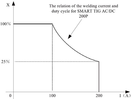
DUTY CYCLE & OVER HEAT
The letter ‘X’ stands for duty cycle, which is defined as the
proportion of the time that a machine can work
continuously within a certain time (10 minutes). The rated
duty cycle means the proportion of the time that a
machine can work continuously within 10 minutes when it
outputs the rated welding current.
The relation between the duty cycle ‘X’ and the output
welding current ‘I’ is shown as the right figure.
If the welding unit is overheating, the IGBT overheat
protection unit inside it will send an instruction to cut the
output current and the overheat pilot light will illuminate
on the front panel. At this time, the machine should be
removed from service and cool down for 15 minutes to
cool the welding unit. When operating the machine
again, the welding output current or the duty cycle should Fig. 10
be reduced.
WELDING POLARITY CONNECTIONS
Choosing either DC Electrode Positive (DCEP) or DC
Electrode Negative (DCEN) depends on the type of
welding, the metal properties and the gas or electrode
covering. Please consult a welding manual to determine
the best method.
The welding torch is hooked up to the positive output
(A) for DCEP and to the negative output (C) for DCEN.
The ground clamp cable is connected to the other
polarity outlet.
When used in AC mode, check the welding rod for the
appropriate polarity to use.
DC Electrode Positive DC Electrode Negative
TIG SET UP Fig. 11
1. The ground clamp cable is connected to the welding unit’s positive polarity output (A).
2. The welding torch is connected to the welding unit’s negative polarity output (C).
3. The torch control cable is inserted into the aero socket (B).
4. A gas cylinder is attached to the shield gas input port (G) via a hose.
5. The welding torch hose is attached to the shield gas connector (D). The shield gas will flow to the welding torch
when the torch is activated.
6. On the Control Panel select the parameters for the type of welding application by referencing the control panel
section in this manual (see Fig. 1 and 2).
WELDING CURRENT ADJUSTMENT
Welding current range is 10 ~ 200A (TIG) or 10 ~ 170A (MMA). Pre-set the welding current amperage before use. The
amperage is displayed on the control panel (14).
14 For technical questions call 1-800-665-8685V4.1 SMART TIG AC/DC-200P Inverter Welding Machine 8560237
DUTY CYCLE
The welding unit’s duty cycle rating defines how long the operator can weld before allowing the welding unit to cool. The
duty cycle is a percentage of a 10 minute period. The welding unit must cool for the remainder of the cycle. This welding
unit has a duty cycle rating of 15% at the rated output (see Specifications). This means that the user can weld for 1-1/2
minutes and then rest the welding unit for 8-1/2 minutes before using it again.
The welding unit may stop before the 1-1/2 minute duty cycle time limit. Reduce the wire speed slightly and tune in the
welding unit at the lowest wire speed setting that still produces a smooth arc. Welding with the wire speed set too high
causes excessive current draw and shortens the duty cycle.
INTERNAL THERMAL PROTECTION
Constantly exceeding the duty cycle can damage the welding unit. An internal thermal protector will open when the duty
cycle is exceeded, shutting OFF all welding unit functions except the cooling fan. Leave the welding unit turned ON with
the fan running. The thermal protector will automatically reset and the welding unit will function normally again once it
has cooled.
Wait at least another 10 minutes after the thermal protector opens before resuming welding. Starting before this
additional time may result in a shortened duty cycle.
SHORT CIRCUIT PROTECTION
Sometimes the tungsten electrode will touch the workpiece during the welding process. To prevent a short circuit from
damaging the workpeice or welding unit, this tool will detect the contact and if reduce the current if the contact exceeds
a time limit.
1. TIG/DC/IHF/LIFT: The current will drop to zero (0) within 2 seconds after contact. This will prevent burn off of the
tungsten electrode.
2. MMA: The current will drop to 10A if the contact lasts over 3 seconds.
WELDING OPERATION
The welding unit is suitable for all positions welding for various plates made of stainless steel, carbon steel, alloyed
steel, titanium, aluminum, magnesium, copper, etc., which is also applied to pipe installment, mould mend,
petrochemical, architecture decoration, car repair, bicycle, handicraft and common manufacturing solutions.
AC TIG is used to weld aluminum and magnesium workpieces. The shield gas used is either pure Argon, pure Helium or
an Argon/Helium mixture depending on the workpiece thickness, penetration depth required and the type of weld. The
weld is cleaner with less spatter.
DC TIG is used to weld stainless steel, nickel alloys, copper, titanium and less common metals/alloys. T The shield gas
used is either pure Argon, pure Helium or an Argon/Helium mixture. DC TIG welding produces a cleaner weld than AC
TIG.
The front control panel allow continuous and stepless adjustments of the welding parameters. This includes:
• Real time display for both welding current and voltage.
• Save and recall the current parameters or pre-set the welding parameters separately.
• Welding configuration: DC MMA, AC MMA, DC TIG, AC TIG, DC Pulse TIG and AC Pulse TIG. Parameters for AC
and Pulse can be set separately.
• Ignition methods for TIG, LIFT and High Frequency (HF), with 2T, 4T, Spot, Repeat and I-Spot.
• TIG Spot function can be configured as four welding methods of TIG. The welding duration time can be adjusted
as well.
• TIG repeat function. Swap between two different current levels while welding. This will improve the efficiency of
the welding torch.
• The I-Spot function is used as intelligent spot welding.
• Welding suitable for stainless steel, carbon, copper, aluminum and Al-Mg alloy.
Visit www.princessauto.com for more information 158560237 SMART TIG AC/DC-200P Inverter Welding Machine V4.1
WELDING CONFIGURATION CHARACTERISTICS
1. The DC MMA can be set to positive or negative polarity according to the electrode requirements.
2. AC MMA can avoid electromagnetic flow issues that can arise from use of DC AMA.
3. The DC TIG, DCEP configuration features a stable welding arc, low tungsten electrode loss, more welding current,
plus a narrow and deep weld.
4. The AC TIG (rectangle wave) configuration has a more stable arc than Sine AC TIG. This results in maximum
penetration, minimal tungsten electrode loss and a better clearance effect.
5. The DC Pulsed TIG configuration has the following characteristics:
a. Pulse heating. Metal in the molten pool remains at a high temperature for a short time and then cools quickly,
reducing the possibility of producing a hot crack in materials with thermal sensitivity.
b. Little heat is transferred to the workpiece. The arc energy is focused on the welding spot. This is suitable for
welding a thin sheet.
c. Control the heat input and size of the molten pool. The penetration depth is even. This is suitable for welding by
one side and forming by two sides and all position welding for pipe.
d. High frequency arc is suitable for high welding speed to improve the productivity.
6. The AC Pulse TIG provides the advantages of DC Pulsed TIG for aluminum workpieces.
CHOOSE A WELDING LOCATION
Selecting the proper location to use the welding unit can significantly increase the welding unit’s performance, reliability
and lifespan.
Locate the welding unit in an environment that is clean and dry. Place the welding unit to ensure free circulation of air
around all sides of the welding unit. Dust and dirt can accumulate on the moving parts of the welding unit. Debris can
retain moisture and that can increase wear for moving parts.
The power outlet used for the welding unit must be properly grounded and the welding unit must be the only load on the
electrical circuit. See Power Requirements in the Installation section.
Turn the welding unit OFF before plugging into appropriate 230 volt 35 amp power outlet.
The use of an extension cord is discouraged for arc welding units. Extension cord use will significantly degrade the
performance of the welding unit.
OPERATION ENVIRONMENT
1. Operate below a height of 1,000 meters above sea level.
2. Operating temperature range: - 10°C to +40°C (14°F to 104°F).
3. Relative humidity is below 90% (+20°C / +68°F).
4. Preferably position the machine above the floor level, the maximum angle should not exceed 15°.
5. Protect the machine from heavy rain or against direct sunlight in hot circumstances.
6. Make sure there is sufficient ventilation during welding.
7. Maintain at least 12 in. (30 cm) between the machine and any walls.
PREPARING THE TORCH
The torch will require cleaning and preparation before each use. Any previous welding will leave carbon deposits and
molten bits on the nozzle and welding tip. The metal beads and carbon deposits will disrupt the shielding gas flow from
the nozzle, resulting in uneven protection of the weld puddle.
1. Remove the nozzle and inspect for molten beads inside the nozzle and on the end.
2. Insert a cylindrical metal brush into the cup opening and rotate while moving the brush up and down to remove the
metal beads and deposits.
3. The tungsten electrode may be shorter due to burn off. Loosen the collet and pull the tungsten electrode forward.
Retighten the collet by hand.
4. Screw the nozzle back into place and the torch is ready for use.
16 For technical questions call 1-800-665-8685V4.1 SMART TIG AC/DC-200P Inverter Welding Machine 8560237
CHECK THE GAS FLOW FOR TIG WELDING
Checking that the gas is flowing does not require the welding unit to be turned ON or plugged in.
Avoid damaging the regulator by ensuring the regulator valve is closed before opening the cylinder valve. Stand to the
side of the cylinder when opening the valve to avoid being struck if the regulator is ejected. Ensure there are no
bystanders nearby that could be struck by an ejected regulator. A serious injury could result.
1. Slowly crack open the cylinder valve, then open all the way.
2. Tum the regulator adjustment knob counterclockwise until the knob is fairly loose.
3. Press the gas-test button (3) and press the torch switch. Gas will flow for 5 seconds.
4. Listen and feel for gas flowing from the end of the welding torch. If no gas is heard or felt, verify all steps in Install
the Shielding Gas Cylinder.
5. Turn the adjustment knob clockwise to increase gas flow; counterclockwise to reduce flow.
6. Set the gas flow to the Cubic Feet per Hour based on the nozzle size (see Table 2) and type of welding you are doing.
The CFH is an approximate setting. Adjust the CFH gas flow to match the welding conditions.
TIG Welding Gas Flow (Argon)
Welding Current Direct Current (DC) Positive Connection Alternating Current (AC)
Nozzle Size Flow Rate Nozzle Size Flow Rate
10 to 100A 4 to 9.5 mm 4 ~ 5 L/min 9 ~ 11 CFH 8 to 9.5 mm 6 ~ 8 L/min 13 ~ 17 CFH
101 to 150A 4 to 9.5 mm 4 ~ 7 L/min 9 ~ 15 CFH 9.5 to 11 mm 7 ~ 10 L/min 15 ~ 21 CFH
151 to 200A 6 to 13 mm 6 ~ 8 L/min 13 ~ 17 CFH 11 to 13 mm 7 ~ 10 L/min 15 ~ 21 CFH
Table 2
ATTACHING THE GROUND CLAMP
1. Clean off dirt, oil, rust, scale, oxidation and paint from the workpiece where the ground clamp will be attached.
2. Attach the ground clamp to the workpiece. Connect the ground clamp directly to the workpiece and as close to the
weld as possible to prevent the welding current from traveling along an unexpected path, creating an electric shock
or fire hazard.
If this is not possible, connect the ground clamp to metal attached to the workpiece, but is not electrically
insulated from it. The metal must be of equal or greater thickness than the workpiece when using this alternate
attachment point.
TURN THE POWER ON
1. Plug the welding unit power cord into an outlet that meets the specified power requirements (see Specifications).
2. Press the power switch to turn the welding unit ON.
WARNING! The welding unit is ‘live’ once turned on and can cause serious electrical and burn injuries if
mishandled. Take all precautions listed in this manual when handling the welding unit.
SELECT THE WELDING PARAMETERS
1. Press the AC/DC selection key (1) to choose the type of current.
2. Select the welding parameters based on the welding task (see Control Panel).
WELDING
The welding unit is ready for use. Ensure all safety equipment and procedures are in place before proceeding. Welding
outside or in a draft may require a wind break to keep the shielding gas from being blown from the weld.
Visit www.princessauto.com for more information 178560237 SMART TIG AC/DC-200P Inverter Welding Machine V4.1
STRIKING ARC METHOD
1. Lift Arc: Use this method when welding brittle
or hard steel.
a. Hold the electrode (Fig. 12-1) upright above
the workpiece, no closer than 4 mm.
b. Tap down onto the workpeice (Fig. 12-2)
and quickly lift up about 2 to 4 mm to ignite
the arc (Fig. 12-3). The tapping motion
shouldn’t last more than 2 seconds.
Fig. 12
2. HF Ignition: Allows the arc to start without
touching the workpiece
a. Hold the tungsten electrode within 2 to 4 mm.
b. An arc will establish itself.
IMPORTANT! When operating the welding unit in HF ignition mode, the ignition spark can cause interferences in
equipment near the welding unit. Be sure to take specially safety precautions or shielding measures.
3. Scratch Arc: Hold the electrode to scrape the workpiece
for striking an arc. This method is used primarily for
stick welding.
a. Place the welding torch at an angle (Fig. 13).
b. Scrape the electrode along the workpiece.
c. Lift the welding torch 2 to 4 mm to create an arc.
TIG WELDING (4T OPERATION)
Fig. 13
TIG welding set to 4T is suitable for the welding of medium
thick plates. The welding unit can preset the start current
(upslope time) and crater current (downslope time). This allows the welding unit to switch from one setting to the next
by pressing or releasing the torch switch as instructed below.
1. Press and hold the torch switch. The electromagnetic gas valve is turned on. The shielding gas starts to flow.
2. Pre-gas time lasts between 0.1 to 1 second.
3. The arc is ignited at the starting current value.
4. Release the torch switch and the output current rises to the full value. The upslope time can be adjusted.
5. The welding unit begins the welding task. The output current remains constant, unless pulse is selected.
a. Pulse output alternates between the base and welding current during the welding process.
6. Pressing the torch switch again drops the current output to the downslope setting to the crater current output to
finish the weld. The downslope time can be adjusted.
7. Release the torch switch to stop the arc. The gas will continue to flow to protect the weld for 0.1 to 10 seconds. The
post-gas can be set with the adjustment knob on the front panel
8. The electromagnetic valve closes and stops the gas from flowing.
9. The welding task is complete.
TIG WELDING (2T OPERATION)
TIG welding to 2T does not use either preset start current (upslope) or crater current (downslope) function. The 2T
setting is suitable for the re-tack welding, transient welding or thin plate welding.
1. Press and hold the torch switch. The electromagnetic gas valve is turned on and the shielding gas starts to flow.
2. Pre-gas time lasts between 0.1 to 1 second.
3. The arc ignites and the output current rises to the set welding current (Iw or Ib) from the minimum welding current.
4. The welding unit begins the welding task. The output current remains constant, unless pulse is selected.
a. Pulse output alternates between the base and welding current during the welding process.
5. Release the torch switch and the welding current drops to the minimum welding current from the setting current (Iw
or lb) and then arc is turned off.
18 For technical questions call 1-800-665-8685V4.1 SMART TIG AC/DC-200P Inverter Welding Machine 8560237
6. The gas will continue to flow to protect the weld for 0.1 to 10 seconds. The post-gas can be set with the adjustment
knob on the front panel
7. The electromagnetic valve closes and stops the gas from flowing.
8. The welding task is complete.
SHUTTING DOWN THE WELDING UNIT
Once the welding job is complete, the welding unit and gas cylinder must be shut down. The torch nozzle will still be hot.
Take precautions to avoid a burn injury.
1. Turn off the welding unit.
2. Disconnect the ground clamp to prevent an electrical circuit from forming.
3. Place the torch down so the hot nozzle is not touching anything flammable.
4. Shut the gas cylinder valve by turning clockwise. Leave the regulator valve open.
5. Switch the welding unit on.
6. Pull the trigger until the regulator shows zero pressure and no gas is flowing from the nozzle.
7. Turn the welding unit off and store the torch.
8. Shut the regulator valve.
ARC WELDING DEFECT AND PREVENTATIVE TIPS
Defect Reasons Preventative Methods
Welding seam The groove angle is not proper. Choose the proper groove angle and assembly gap
doesn’t meet to improve the assembly quality.
The root face and assembly gap are not
the welding
equal. Choose the proper welding parameters.
standards.
Welding technical parameters are incorrect. More practice is required.
More welding experience is required.
Crater Abrupt end to welding causes puddle to Gradually reduce the current and continue to feed
cool too quickly. rod/wire into the welding puddle to allow it to slowly
cool. Move the rod to the side of the puddle before
Too much current in the welding of a thin
removing it.
plate.
Reduce current when welding thin plate.
Undercut Not enough current applied to weld. Choose the proper welding current and speed of
travel.
Arc length is too long.
Reduce gap between electrode and workpiece to
The electrode angle is wrong or improperly
control arc length.
applied to weld.
Consult a welding manual to determine the
correct angle, speed and current for the welding
task attempted.
Incomplete The groove angle or gap is too small and Adjust the welding technique for the groove size.
penetration the root face is too large for a secure weld.
Select the suitable welding current and speed.
Welding parameters are not correct for
Reduce gap between electrode and workpiece to
materials being welded.
control arc length.
Arc length is too long.
Check that correct gas is being used at the correct
Shield gas is blown away. CFM to prevent turbulence. Erect a wind shield
around welding area.
More experience is required.
More practice is required.
Visit www.princessauto.com for more information 198560237 SMART TIG AC/DC-200P Inverter Welding Machine V4.1
Defect Reasons Preventative Methods
Incomplete The welding thermal input is too low. Chose the welding parameters correctly.
fusion
There is rust and dust on the side of the Clean the workpiece before beginning the weld.
groove.
Clear the layers better to prevent contamination.
The slag between the layers is not cleared
well.
Overlap The temperature of the molten pool is too Chose parameters based on the welding different
high. position.
The liquid metal solidifies slowly. Carefully control the molten hole size.
Hot crack. In the process of solidification, internal Strictly control the percentage of impurities in the
crystal segregation is caused. At the same welding material.
time, with the effect of welding stress, a hot
Adjust the structure of welding material.
crack is formed.
Use a basic electrode.
Cold crack. Three reasons will cause a cold crack: Consult welding manual to determine temperatures
to bake workpiece before and after welding to
The structure forms martensite, which are
prevent martensite from forming.
brittle, micro-cracks.
Remove the fouled or impure matter before use,
The residual stress is caused by big
reduce the percentage of hydrogen.
restraint intensity.
Use appropriate parameters and heat input.
There is residual hydrogen in the welding
gap. Adopt a low hydrogen type of
basic electrode. After welding, perform
dehydrogenation at once.
Blowhole There are some impurities such as dust, oil, Clear out the impurities around the groove for about
rust or water on the workpiece surface and 20 to 30 mm.
groove.
Take care to dry the electrode
The coating of the electrode is damp.
Adjust the welding current or the electrode’s travel
Current is too low or speed is too great in speed.
the welding.
Reduce the arc length, adjust the current or improve
The arc is too long, the current is too low or welding techniques to create a molten pool.
the molten pool protection is inadequate.
Replace the electrode with an undamaged one.
The current is too high, the coating of the Reduce the welding current based on the type of
electrode has fallen off and there is electrode and welding task.
inadequate shielding gas.
Do not use improper electrodes.
The electrode is not the proper type.
Inclusion and The slag does not clear properly in the Select the electrode with good slag detachability.
slag inclusion. middle layer in the welding process. Make sure to clear the slag in the layers.
Current is too low or welding speed is too Select the correct welding current and speed of
slow. travel with the electrode.
The welding electrode is wrong for the Choose an electrode appropriate for the welding
workpiece material. task.
The groove design and processing are not Adjust the electrode angle and the manipulation
proper. method.
20 For technical questions call 1-800-665-8685V4.1 SMART TIG AC/DC-200P Inverter Welding Machine 8560237 MAINTENANCE In order to guarantee that the arc welding unit operates efficiently and safely, it must be maintained regularly. WARNING! Make sure that the main power switch has been disabled before attempting any type of maintenance to the machine. For safety while maintaining the machine, remove from the power source and wait for 3 minutes to allow the capacity voltage to drop to a safe voltage 1. Maintain the tool with care. A tool in good condition is efficient, easier to control and will have fewer problems. 2. Follow instructions for lubricating and changing accessories. 3. Inspect the tool fittings, alignment and hoses and power supply cord periodically. Have damaged or worn components repaired or replaced by an authorized technician. 4. When servicing, use only identical replacement parts. Only use accessories intended for use with this tool. Replace damaged parts immediately. 5. Keep the wire drive compartment lid closed at all times unless the wire needs to be changed or the drive tension needs adjusting. 6. Keep all parts of the welding unit, such as nozzles and tungsten electrode, clean and replace when necessary (see Consumable Maintenance and Troubleshooting). 7. Replace ground cable, ground clamp or torch assembly when damaged or worn. 8. Periodically clean dust, dirt, grease, etc. from your welding unit. Every six months or as necessary, remove the side panels from the welding unit and air-blow any dust and dirt that may have accumulated inside the welding unit. 9. Maintain the tool’s label and name plate. These carry important information. If unreadable or missing, contact Princess Auto Ltd. for replacements. WARNING! If the equipment does not work normally, stop using the machine at once and check for any signs of trouble. Have the machine inspected by a qualified professional. Do not allow untrained persons to check, clean or repair the machine. Only use replacement parts that have been approved by the manufacturer. MAINTENANCE - CONSUMABLES Maintain the consumables to avoid the need for premature replacement of the torch assembly. MAINTAINING THE TUNGSTEN ELECTRODE The tungsten rod is not consumed during welding, but it can become shorter due to the end being burned off during the welding process. When this occurs, loosen the collet and pull the tungsten electrode forward (see Preparing the torch). This method is also used to replace the tungsten rod. The end of the electrode may be ground to a point to provide better transfer of the electric arc for DCEN or AC welding. Use a dedicated grinding wheel to prevent contamination of the rod. The tungsten rod should be held point forward when applied to the grinding wheel. Grinding the tungsten rod end against the side can create parallel grooves along the length of the point. This can negatively affect the focus of the welding arc and create poor welds. MAINTAINING THE NOZZLE The nozzle directs the shielding gas to the weld puddle, determines the size of the shielding gas area and prevents the electrically hot contact tip from contacting the workpiece. NOTICE! Clean the nozzle of slag when needed. During the welding process, spatter and slag will build up inside the nozzle. Failure to clean and/or replace the nozzle in a timely fashion will damage the front end of the torch assembly. 1. Stop welding and clean any accumulated slag or spatter from the nozzle every 5 to 10 minutes of welding time. 2. Overhead welding may allow molten metal to drip from the weld puddle into the nozzle. Stop welding immediately and clean the nozzle. 3. Replace the nozzle when you can no longer clean the slag out. Failure to keep the nozzle adequately cleaned can result in a restricted nozzle. The slag build up in the nozzle affects the direction, concentration and/or flow rate of the shielding gas. This problem can cause porous, brittle welds and reduce penetration. Visit www.princessauto.com for more information 21
Vous pouvez aussi lire