SR LIGHT Coffret de commande pour filtration de piscines SRF-1 / SRF-100 - Aquasilver
←
→
Transcription du contenu de la page
Si votre navigateur ne rend pas la page correctement, lisez s'il vous plaît le contenu de la page ci-dessous
SR LIGHT
Coffret de commande
pour filtration de piscines
SRF-1 / SRF-100

                   NOTICE D’INSTALLATION ET CONSEILS D’UTILISATION
                   (À lire attentivement et à conserver pour utilisation ultérieure.)

                                                                         FR - PAGE 1 | EN - PAGE 11 | DE - SEITE 21 | ES - PÁGINA 31

    CONSTRUCTION & RÉNOVATION                                              2021/01 - Indice de révision : G - Code : 32602    1/40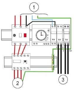
1. FIXATION....................................................................................................... 4
    1.1     Instructions pour le câblage...................................................................................................5
            1.1.1 SRF-1...........................................................................................................................6
            1.1.2 SRF-100.......................................................................................................................7

2. FONCTIONNEMENT DE L’HORLOGE........................................................... 8

3. SCHÉMA ÉLECTRIQUE................................................................................. 9
    3.1     SRF-1........................................................................................................................................9
    3.2     SRF-100....................................................................................................................................9

2/40                 2021/01 - Indice de révision : G - Code : 32602                                   CONSTRUCTION & RÉNOVATION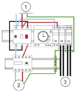
RECOMMANDATIONS IMPORTANTES

 L’installation d’un coffret électrique doit être réalisée dans les règles de l’art, suivant les normes en
 vigueur.
 L’alimentation électrique du coffret devra être protégée en amont par un disjoncteur différentiel de 30
 mA.
 Avant toute intervention nécessitant la dépose de la façe avant, s’assurer que l’alimentation électrique
 est coupée en amont du coffret.

 Le coffret doit être complété par un disjoncteur approprié à la puissance du moteur qu’il doit alimenter.
 L’installation d’un disjoncteur trop puissant peut entraîner la déterioration du moteur électrique.
 Le fusible doit être remplacé impérativement par un fusible de mêmes caractéristiques.

Utilisation du commutateur “filtration”

• Position “M” : Fonctionnement continu de la filtration.
• Position “A” : Fonctionnement de la filtration suivant la programmation de l’horloge.
• Position “0” : Arrêt permanent de la filtration.

          CONSTRUCTION & RÉNOVATION                        2021/01 - Indice de révision : G - Code : 32602   3/40
1. FIXATION

              1                                                                     2

• Retirer les deux vis dans la partie inférieure                        • Retirer le capot.
  du coffret.

                  3                                                             4

• Défoncer les trous de fixation de la platine.                         • Utiliser la platine comme gabarit de perçage.

          5                                                                6

• Fixer la platine au mur à l’aide des chevilles                        • Accrocher le disjoncteur-moteur sur le rail
  et vis fournies.                                                        au-dessus du contacteur.

4/40                  2021/01 - Indice de révision : G - Code : 32602                   CONSTRUCTION & RÉNOVATION
7 8
• Mettre en place les presse-étoupes et réaliser • Replacer le capot en accrochant d’abord la
les connexions. partie inférieure.
9 10
• Fermer le capot en le claquant par le haut. • Replacer les deux vis dans la partie inférieure
du coffret.
1.1 Instructions pour le câblage
Les instructions ci- après concernent uniquement les connexions qui doivent être effectuées par l’installateur.
Le câblage du coffret est déjà réalisé lors de la fabrication et ne doit en aucun cas être modifié au risque
de dégradations ou d’accidents.
Il est primordial d’utiliser des câbles de section suffisante en fonction de l’intensité qu’ils doivent véhiculer
(particulièrement pour les projecteurs).
Vérifier également le serrage correct des connexions.
Un câble de section insuffisante ou une connexion mal serrée s’échauffe et peut provoquer un début
d’incendie.
CONSTRUCTION & RÉNOVATION 2021/01 - Indice de révision : G - Code : 32602 5/401.1.1 SRF-1
Câblage 380 V triphasé
1 : Alimentation 380 V + Neutre + Terre
2 : Départ 380 V + Terre vers moteur
1
1
0
10 A
1
0
10 A
I O
T
I O
T
2
Câblage 230 V monophasé
1 : Alimentation 230 V + Terre
2 : Départ 230 V + Terre vers moteur
1
1
0
10 A
1
0
10 A
I O
T
I O
T
2
6/40 2021/01 - Indice de révision : G - Code : 32602 CONSTRUCTION & RÉNOVATION1.1.2 SRF-100
Câblage 380 V triphasé
1 : Alimentation 380 V + Neutre + Terre
2 : Départ 380 V + Terre vers moteur
3 : Départ 12 V vers projecteur(s)
Câblage 230 V monophasé
1 : Alimentation 230 V + Terre
2 : Départ 230 V + Terre vers moteur
3 : Départ 12 V vers projecteur(s)
CONSTRUCTION & RÉNOVATION 2021/01 - Indice de révision : G - Code : 32602 7/402. FONCTIONNEMENT DE L’HORLOGE
Mode d’emploi
PROGRAMMATION :
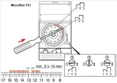
1. Mettez l’horloge à l’heure en synchronisant la roue sur l’heure réelle. Utilisez un tournevis que vous
introduirez au centre de la roue pour positionner les aiguilles comme sur une montre : la grande aiguille
représente les minutes, la petite aiguille représente les heures.
2. Tournez ensuite la couronne de façon à mettre le repère en face de l’heure. Sur la figure, le réglage
correspond à 10h.
3. Pour définir des plages horaires de commutation (les plages horaires pendant lesquelles la filtration
sera en fonctionnement), poussez les segments correspondants vers l’extérieur du cadran de l’horloge,
comme représenté à la Figure ci-dessus. Chaque segment représente 15 minutes.
4. Placez enfin le commutateur rotatif sur la fonction souhaitée :
O I
Automatique
Arrêt (out) (fonctionnement de la filtration Marche forcée (in)
aux heures réglées sur l’horloge)
8/40 2021/01 - Indice de révision : G - Code : 32602 CONSTRUCTION & RÉNOVATION3. SCHÉMA ÉLECTRIQUE
3.1 SRF-1
T N L1 L2 L3
F1 4 Amp
S1
DISJ-1 1 3 5 M A
0
1 U
4 W
2 4 6
1 3 5
A1
KM 1 KM1
2 4 6 A2
F1 4 Amp
M
3.2 SRF-100
• Puissance maximum de 50 VA au niveau des
deux portes fusibles.
• Fusible 6A type 10x38 GG sur les deux sorties
secondaires, adapté aux projecteurs LED.
CONSTRUCTION & RÉNOVATION 2021/01 - Indice de révision : G - Code : 32602 9/40Notes 10/40 2021/01 - Indice de révision : G - Code : 32602 CONSTRUCTION & RÉNOVATION
SR LIGHT
Electrical panels for swimming
pool filtration systems
SRF-1 / SRF-100

                 INSTALLATION AND OPERATING INSTRUCTIONS
                 (Please read carefully and keep for future reference.)

                                                                    FR - PAGE 1 | EN - PAGE 11 | DE - SEITE 21 | ES - PÁGINA 31

  CONSTRUCTION & RÉNOVATION                                           2021/01 - Indice de révision : G - Code : 32602   11/40
1. MOUNTING.................................................................................................. 14
1.1 Wiring instructions................................................................................................................15
1.1.1 SRF-1.........................................................................................................................16
1.1.2 SRF-100.....................................................................................................................17
2. TIMER OPERATION..................................................................................... 18
3. WIRING DIAGRAM....................................................................................... 19
3.1 SRF-1......................................................................................................................................19
3.2 SRF-100..................................................................................................................................19
12/40 2021/01 - Indice de révision : G - Code : 32602 CONSTRUCTION & RÉNOVATIONIMPORTANT RECOMMENDATIONS
The electrical panel must be installed by professionals in accordance with the standards in effect.
The power supply of the electrical panel must be protected by a 30 mA differential circuit breaker at the
top of the line.
Make sure that the power supply has been disconnected upstream from the electrical panel prior to any
action requiring the removal of the front plate.
The electrical panel must be equipped with a circuit breaker suitably rated for the electrical power of
the motor to be supplied.
Installation of a circuit breaker that is too powerful could cause damage to the electrical motor.
If you replace the fuse, make sure to use a fuse with an identical rating.
Use of the «filter» switch
• “M” position : Continuous filtration mode.
• “A” position : Timer programmed filtration mode.
• “0” position : Permanent stop position.
CONSTRUCTION & RÉNOVATION 2021/01 - Indice de révision : G - Code : 32602 13/401. MOUNTING
1 2
• Remove the two screws from the bottom part • Remove the cover.
of the electrical panel.
3 4
• Punch the screw holes out of the mounting • Use the mounting plate as a drilling template.
plate.
5 6
• Use the plugs and screws provided to attach • Attach the motor circuit breaker to the rail
the plate to the wall. above the contactor.
14/40 2021/01 - Indice de révision : G - Code : 32602 CONSTRUCTION & RÉNOVATION7 8
• Install the cable glands and proceed with the • Replace the casing, attaching the bottom
wiring. section first.
9 10
• Close the casing by pressing on the upper • Insert the two screws back to the bottom part
section until it clicks into place. of the control panel.
1.1 Wiring instructions
The following instructions apply only to connections to be carried out by an installer. The electrical panel is
pre-wired in the factory. The panel wring should not be altered under any circumstances to avoid any risk
of damage or accidents.
The cable cross section must be correctly sized for the current carried (especially in the case of underwater
lights).
Check that connections are correctly tightened.
An inadequately sized cable or badly tightened connection could start a fire.
CONSTRUCTION & RÉNOVATION 2021/01 - Indice de révision : G - Code : 32602 15/401.1.1 SRF-1
Wiring 380 V three-phase
1 : Power supply 380 V + Neutral + Earth
2 : Outlet 380 V + Earth to the motor
1
1
0
10 A
1
0
10 A
I O
T
I O
T
2
Wiring 230 V single-phase
1 : Power supply 230 V + Earth
2 : Outlet 230 V + Earth to the motor
1
1
0
10 A
1
0
10 A
I O
T
I O
T
2
16/40 2021/01 - Indice de révision : G - Code : 32602 CONSTRUCTION & RÉNOVATION1.1.2 SRF-100
Wiring 380 V three-phase
1 : Power supply 380 V + Neutral + Earth
2 : Outlet 380 V + Earth to the motor
3 : Outlet 12 V to the underwater lights
Wiring 230 V single-phase
1 : Power supply 230 V + Earth
2 : Electric outlet 230 V + Earth to the motor
3 : Outlet 12 V to the underwater lights
CONSTRUCTION & RÉNOVATION 2021/01 - Indice de révision : G - Code : 32602 17/402. TIMER OPERATION
Instructions for use
PROGRAMMATION:
1. Set the timer to the right time by synchronizing the wheel to the current time. Insert a screw driver
into the centre of the wheel to position the needles similar to the hands on a watch: the big needle
corresponds to the minutes, the small hand shows the hours.
2. Next, rotate the ring until the time is aligned with the pointer. In the figure above, the setting corresponds
to 10 am.
3. To define the switching intervals (the intervals during which filtration should run), push the relevant
segments toward the exterior of the timer dial as shown in the figure above. Each segment represents
15 minutes.
4. Lastly, turn the rotary switch to the desired mode:
O I
Automatic
Stopped (out) (filter runs during the intervals Forced on (in)
set on the timer)
18/40 2021/01 - Indice de révision : G - Code : 32602 CONSTRUCTION & RÉNOVATION3. WIRING DIAGRAM
3.1 SRF-1
T N L1 L2 L3
F1 4 Amp
S1
DISJ-1 1 3 5 M A
0
1 U
4 W
2 4 6
1 3 5
A1
KM 1 KM1
2 4 6 A2
F1 4 Amp
M
3.2 SRF-100
• Maximum power of 50 VA at the two fuse doors.
• 6A fuse type 10x38 GG on both secondary
outputs, suitable for LED projectors.
CONSTRUCTION & RÉNOVATION 2021/01 - Indice de révision : G - Code : 32602 19/40Notes 20/40 2021/01 - Indice de révision : G - Code : 32602 CONSTRUCTION & RÉNOVATION
SR LIGHT
Steuergeräte für Filteranlagen
für Schwimmbecken
SRF-1 / SRF-100

                   MONTAGE- UND BEDIENUNGSANLEITUNG
                   (Bitte lesen Sie sich diese Anleitung sorgfältig durch und bewahren Sie sie auf.)

                                                                      FR - PAGE 1 | EN - PAGE 11 | DE - SEITE 21 | ES - PÁGINA 31

    CONSTRUCTION & RÉNOVATION                                           2021/01 - Indice de révision : G - Code : 32602   21/40
1. BEFESTIGUNG............................................................................................ 24
1.1 Hinweise für die Verkabelung...............................................................................................25
1.1.1 SRF-1.........................................................................................................................26
1.1.2 SRF-100.....................................................................................................................27
2. FUNKTIONSWEISE DER ZEITSCHALTUHR............................................... 28
3. SCHALTPLAN.............................................................................................. 29
3.1 SRF-1......................................................................................................................................29
3.2 SRF-100..................................................................................................................................29
22/40 2021/01 - Indice de révision : G - Code : 32602 CONSTRUCTION & RÉNOVATIONWICHTIGE HINWEISE
Das Steuergerät muss nach den geltenden Richtlinien von einem Fachmann installiert werden.
Zum Schutz der Stromversorgung des Steuerkastens muss an der Zufuhrleitung ein FI-Schalter 30 mA
montiert werden.
Vor jeder Maßnahme, die die Entfernung der Frontplatte erfordert, muss sicher gestellt werden, das die
Stromversorgung an der Zufuhrleitung unterbrochen ist.
Das Steuergerät muss zusätzlich mit einem für den Motor, der über das Steuergerät mit Strom versorgt
wird, geeigneten Unterbrecherkontakt ausgerüstet sein.
Wenn ein zu starker Unterbrecherkontakt montiert wird, kann der elektrische Motor beschädigt werden.
Wenn Sie die Sicherung ersetzen, müssen Sie ein Modell mit den gleichen technischen Merkmalen
verwenden.
Verwendung des Schalters «FILTER»
• Position “M” : Dauerbetrieb des Filters.
• Position “A” : Filterbetrieb nach Programmierung der Zeitschaltuhr.
• Position “0” : Filtration ausgeschaltet.
CONSTRUCTION & RÉNOVATION 2021/01 - Indice de révision : G - Code : 32602 23/401. BEFESTIGUNG
1 2
• Entfernen Sie die beiden Schrauben am • Entfernen Sie das Gehäuse.
unteren Teil des Steuerkastens.
3 4
• Drücken Sie die Löcher für die • Verwenden Sie die Montageplatte als
Befestigungsschrauben an der Montageplatte Bohrschablone.
ein.
5 6
• Befestigen Sie die Platte mit Hilfe der • Befestigen Sie den Motor FI-Schalter an der
mitgelieferten Dübel und Schrauben an der Schiene über dem Schütz.
Wand.
24/40 2021/01 - Indice de révision : G - Code : 32602 CONSTRUCTION & RÉNOVATION7 8
• Installieren Sie die Kabeldurchführungen und • Setzen Sie das Gehäuse wieder auf; beginnen
nehmen Sie die Anschlüsse vor. Sie dabei mit dem unteren Abschnitt.
9 10
• Schließen Sie das Gehäuse durch Drücken des • Setzen Sie die beiden Schrauben unten am
oberen Abschnitts, bis es mit einem Geräusch Steuerkasten wieder ein.
einrastet.
1.1 Hinweise für die Verkabelung
Die nachfolgenden Anweisungen gelten nur für die von einem Installateur ausgeführten Anschlussarbeiten.
Die Verkabelung des Steuerkastens erfolgt werkseitig und darf auf keinen Fall verändert werden, da dies
zu Schäden am Steuerkasten oder sogar zu Unfällen führen könnte.
Verwenden Sie nur Kabel mit passenden Querschnitten in Anbetracht der elektrischen Belastung der
Kabel (v. a. bei Scheinwerfern).
Achten Sie auf fest sitzende Verbindungen.
Wenn die Kabelquerschnitte unzureichend sind und die Verbindungen nicht fest sitzen, können sie sich
erhitzen und sogar einen Brand verursachen..
CONSTRUCTION & RÉNOVATION 2021/01 - Indice de révision : G - Code : 32602 25/401.1.1 SRF-1
Verkabelung 380V dreiphasig
1 : Spannungsversorgung 380 V + Neutral + Erde
2 : Ausgang 380 V + Erde zum Motor
1
1
0
10 A
1
0
10 A
I O
T
I O
T
2
Verkabelung 230V einphasig
1 : Spannungsversorgung 230 V + Erde
2 : Ausgang 230 V + Erde zum Motor
1
1
0
10 A
1
0
10 A
I O
T
I O
T
2
26/40 2021/01 - Indice de révision : G - Code : 32602 CONSTRUCTION & RÉNOVATION1.1.2 SRF-100
Verkabelung 380V dreiphasig
1 : Spannungsversorgung 380 V + Neutral + Erde
2 : Ausgang 380 V + Erde zum Motor
3 : Ausgang 12 V zu den Scheinwerfern
Verkabelung 230V einphasig
1 : Stromversorgung 230 V + Erde
2 : Ausgang 230 V + Erde zum Motor
3 : Ausgang 12 V zu den Scheinwerfern
CONSTRUCTION & RÉNOVATION 2021/01 - Indice de révision : G - Code : 32602 27/402. FUNKTIONSWEISE DER ZEITSCHALTUHR
Anwendungshinweise
PROGRAMMIEREN :
1. Stellen Sie die Uhrzeit ein, indem Sie das Rad auf die tatsächliche Uhrzeit synchronisieren. Verwenden
Sie einen Schraubendreher, den Sie in der Mitte des Rads einsetzen, um die Nadeln wie auf einer Uhr
zu positionieren: Der große Zeiger stellt die Minuten dar, der kleine Zeiger die Stunden.
2. Drehen Sie dann die Krone so, dass der Marker auf die Uhrzeit zeigt. In der Abbildung ist die
Einstellung auf 10 Uhr.
3. Um Schaltzeitbereiche einzustellen (die Zeiträume, in denen die Filtration in Betrieb ist), drücken Sie
die entsprechenden Segmente aus dem Ziffernblatt. Jedes Segment repräsentiert 15 Minuten.
4. Stellen Sie abschließend den Drehschalter auf die gewünschte Funktion:
O I
Automatisch
Stopped (out) (Filterbetrieb zu den auf der Uhr Manueller Betrieb (in)
eingestellten Zeiten)
28/40 2021/01 - Indice de révision : G - Code : 32602 CONSTRUCTION & RÉNOVATION3. SCHALTPLAN
3.1 SRF-1
T N L1 L2 L3
F1 4 Amp
S1
DISJ-1 1 3 5 M A
0
1 U
4 W
2 4 6
1 3 5
A1
KM 1 KM1
2 4 6 A2
F1 4 Amp
M
3.2 SRF-100
• Maximale Leistung von 50 VA an beiden
Schmelzgates.
• Sicherung 6A Typ 10x38 GG an beiden
Nebenausgängen, geeignet für LED-Projektoren.
CONSTRUCTION & RÉNOVATION 2021/01 - Indice de révision : G - Code : 32602 29/40Notes 30/40 2021/01 - Indice de révision : G - Code : 32602 CONSTRUCTION & RÉNOVATION
SR LIGHT
Cajas de mando para
filtración piscina
SRF-1 / SRF-100

                   INSTRUCCIONES DE INSTALACIÓN
                   Y FUNCIONAMIENTO
                   (Lea atentamente y consérvelo para su uso futuro.)

                                                                    FR - PAGE 1 | EN - PAGE 11 | DE - SEITE 21 | ES - PÁGINA 31

    CONSTRUCTION & RÉNOVATION                                           2021/01 - Indice de révision : G - Code : 32602   31/40
1. FIJACIÓN..................................................................................................... 34
1.1 Instrucciones de cableado....................................................................................................35
1.1.1 SRF-1.........................................................................................................................36
1.1.2 SRF-100.....................................................................................................................37
2. FUNCIONAMIENTO DEL RELOJ................................................................. 38
3. DIAGRAMA ELÉCTRICO............................................................................. 39
3.1 SRF-1......................................................................................................................................39
3.2 SRF-100..................................................................................................................................39
32/40 2021/01 - Indice de révision : G - Code : 32602 CONSTRUCTION & RÉNOVATIONRECOMENDACIONES IMPORTANTES
La instalación de la caja de mando debe ser realizada según las normas vigentes.
La alimentación de la caja de mando debe ser protegida por un disyuntor de 30 mA encima de la línea.
Antes de quitar la placa frontal asegurarse que la alimentación eléctrica ha sido cortada.
La caja de mando debe ser equipada con un disyuntor ajustado a la potencia del motor alimentado por
la caja de mando.
Para sustituir el fusible ha de emplearse uno de las mísmas características.
Empleo del conmutador «filtración»
• Posición “M” : Operación contínua de la filtración.
• Posición “A” : Funcionamiento de la filtración según la programación del reloj.
• Posición “0” : Paro permanente de la filtración.
CONSTRUCTION & RÉNOVATION 2021/01 - Indice de révision : G - Code : 32602 33/401. FIJACIÓN
1 2
• Retirar los dos tornillos de la parte inferior de • Retirar la cubierta.
la caja.
3 4
• Perforar los agujeros de la placa de soporte. • Utilizar la placa de soporte como plantilla de
taladro.
5 6
• Utilizar los tacos y tornillos suministrados para • Fijar el disyuntor en el rail por encima del
fijar la placa en el muro. contactor.
34/40 2021/01 - Indice de révision : G - Code : 32602 CONSTRUCTION & RÉNOVATION7 8
• Montar las prensas estopas y hacer las • Comenzar a fijar la parte inferior para montar
conexiones. la cubierta.
9 10
• Empujar la parte superior hasta que la cubierta • Montar los dos tornillos retirados en la parte
chasquee en su lugar. inferior de la caja.
1.1 Instrucciones de cableado
Las instrucciones siguientes se refieren solamente a conexiones realizadas por un instalador.
El cableado de la caja de mando ha sido realizado en fábrica y no debe ser modificado en ningún caso.
Riesgo de deterioración y de accidente.
El empleo de cables de sección suficiente es muy importante teniendo en cuenta la carga eléctrica
considerable des los cables (sobre todo para proyectores).
Asegurarse también que las conexiones están bien apretadas.
Cables de sección insuficiente o una conexión mal apretada pueden calentarse y provocar un incendio.
CONSTRUCTION & RÉNOVATION 2021/01 - Indice de révision : G - Code : 32602 35/401.1.1 SRF-1
Cableado 380 V trifÁsico
1 : Alimentación 380 V + Neutro + Tierra
2 : Salida 380 V + Tierra en el motor
1
1
0
10 A
1
0
10 A
I O
T
I O
T
2
Cableado 230 V monofÁsico
1 : Alimentación 230 V + Tierra
2 : Salida 230 V + Tierra en el motor
1
1
0
10 A
1
0
10 A
I O
T
I O
T
2
36/40 2021/01 - Indice de révision : G - Code : 32602 CONSTRUCTION & RÉNOVATION1.1.2 SRF-100
Cableado 380 V trifÁsico
1 : Alimentación 380 V + Neutro + Tierra
2 : Salida 380 V + Tierra al motor
3 : Salida 12 V a los proyectores
Cableado 230 V monofÁsico
1 : Alimentación 230 V + Tierra
2 : Salida 230 V + Tierra en el motor
3 : Salida 12 V a los proyectores
CONSTRUCTION & RÉNOVATION 2021/01 - Indice de révision : G - Code : 32602 37/402. FUNCIONAMIENTO DEL RELOJ
Instruccione de empleo
PROGRAMACIÓN :
1. Ponga el reloj a la hora sincronizando la rueda con la hora actual. Use un destornillador que inserte en
el centro de la rueda para colocar las agujas como en un reloj: la mano grande representa los minutos,
la mano pequeña representa las horas).
2. Luego gire la corona para que el marcador esté orientado hacia el tiempo. En la figura, el ajuste es
de 10h.
3. Para establecer los rangos de tiempo de conmutación (los períodos de tiempo durante los cuales la
filtración estará en funcionamiento), empuje los segmentos correspondientes fuera de la esfera del
reloj como se muestra en la Figura. Cada segmento representa 15 minutos.
4. Finalmente, coloque el interruptor giratorio en la función deseada:
O I
Automático
Parada (fuera) (Operación de filtración a horas Marcha forzada (en)
establecidas en el reloj)
38/40 2021/01 - Indice de révision : G - Code : 32602 CONSTRUCTION & RÉNOVATION3. DIAGRAMA ELÉCTRICO
3.1 SRF-1
T N L1 L2 L3
F1 4 Amp
S1
DISJ-1 1 3 5 M A
0
1 U
4 W
2 4 6
1 3 5
A1
KM 1 KM1
2 4 6 A2
F1 4 Amp
M
3.2 SRF-100
• Potencia máxima de 50 VA en las dos puertas
fusibles.
• Fusible 6A tipo 10x38 GG en las dos salidas
secundarias, adecuado para proyectores LED.
CONSTRUCTION & RÉNOVATION 2021/01 - Indice de révision : G - Code : 32602 39/4040/40 2021/01 - Indice de révision : G - Code : 32602 CONSTRUCTION & RÉNOVATION
Vous pouvez aussi lire