Bruciatori di gas ad aria soffiata Gas-Gebläsebrenner Blown type gas burners Brûleurs gaz à air soufflé

La page est créée René Bernard
 
CONTINUER À LIRE
Bruciatori di gas ad aria soffiata Gas-Gebläsebrenner Blown type gas burners Brûleurs gaz à air soufflé
Istruzioni per installazione, uso e manutenzione
Montage und Bedienungs Anleitung
Installation, use and maintenance instructions
Manuel d»entretien

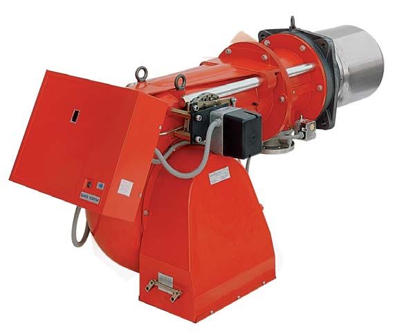
   I        Bruciatori di gas ad aria soffiata
  D         Gas-Gebläsebrenner
 GB         Blown type gas burners
  F         Brûleurs gaz à air soufflé

            Funzionamento bistadio progressivo o modulante
            Zweistufig gleitender oder modulierender Betrieb
            Progressive two-stage or modulating operation
            Fonctionnement à deux allures progressives ou modulant

                                           MODELLO - MODELL       TIPO
       CODICE - CODE
                                            MODEL - MODELE      TYP -TYPE

            3753833                                GAS 8 P/M     538 T1
            3753834                                GAS 8 P/M     538 T1
            3754037                                GAS 9 P/M     540 T1
            3754038                                GAS 9 P/M     540 T1
            3754039                                GAS 9 P/M     540 T1
            3754040                                GAS 9 P/M     540 T1
            3754041                                GAS 9 P/M     540 T1
            3754042                                GAS 9 P/M     540 T1
            3754135                                GAS 10 P/M    541 T1
            3754136                                GAS 10 P/M    541 T1
            3754137                                GAS 10 P/M    541 T1
            3754138                                GAS 10 P/M    541 T1

                                                                          2915641 (4)
I         INDICE                                                                                          D         INHALT
DATI TECNICI . . . . . . . . . . . . . . . . . . . . . . . . . . . . . . . . . pagina 4                   TECHNISCHE ANGABEN . . . . . . . . . . . . . . . . . . . . . . . . . Seite 5
Versioni costruttive . . . . . . . . . . . . . . . . . . . . . . . . . . . . . . . . . . . . 4            Bauvarianten . . . . . . . . . . . . . . . . . . . . . . . . . . . . . . . . . . . . . . . . . 5
Accessori . . . . . . . . . . . . . . . . . . . . . . . . . . . . . . . . . . . . . . . . . . . 8         Zubehör. . . . . . . . . . . . . . . . . . . . . . . . . . . . . . . . . . . . . . . . . . . . . 9
Descrizione bruciatore . . . . . . . . . . . . . . . . . . . . . . . . . . . . . . . . 10                 Brennerbeschreibung . . . . . . . . . . . . . . . . . . . . . . . . . . . . . . . . . 11
Imballo - Peso . . . . . . . . . . . . . . . . . . . . . . . . . . . . . . . . . . . . . . 10             Verpackung - Gewicht. . . . . . . . . . . . . . . . . . . . . . . . . . . . . . . . . 11
Ingombro . . . . . . . . . . . . . . . . . . . . . . . . . . . . . . . . . . . . . . . . . . 10           Abmessungen . . . . . . . . . . . . . . . . . . . . . . . . . . . . . . . . . . . . . . . 11
Corredo . . . . . . . . . . . . . . . . . . . . . . . . . . . . . . . . . . . . . . . . . . . 10          Ausstattung . . . . . . . . . . . . . . . . . . . . . . . . . . . . . . . . . . . . . . . . . 11
Campi di lavoro . . . . . . . . . . . . . . . . . . . . . . . . . . . . . . . . . . . . . 12              Regelbereiche . . . . . . . . . . . . . . . . . . . . . . . . . . . . . . . . . . . . . . . 13
Caldaie commerciali . . . . . . . . . . . . . . . . . . . . . . . . . . . . . . . . . . 12                Handelsübliche Kessel . . . . . . . . . . . . . . . . . . . . . . . . . . . . . . . . 13
Caldaia di prova . . . . . . . . . . . . . . . . . . . . . . . . . . . . . . . . . . . . . 14             Prüfkessel . . . . . . . . . . . . . . . . . . . . . . . . . . . . . . . . . . . . . . . . . . 15
Pressione gas. . . . . . . . . . . . . . . . . . . . . . . . . . . . . . . . . . . . . . . 14             Gasdruck. . . . . . . . . . . . . . . . . . . . . . . . . . . . . . . . . . . . . . . . . . . 15
INSTALLAZIONE. . . . . . . . . . . . . . . . . . . . . . . . . . . . . . . . . . . .             16       INSTALLATION . . . . . . . . . . . . . . . . . . . . . . . . . . . . . . . . . . . . . 17
Piastra caldaia . . . . . . . . . . . . . . . . . . . . . . . . . . . . . . . . . . . . . .      16       Kesselplatte. . . . . . . . . . . . . . . . . . . . . . . . . . . . . . . . . . . . . . . . . 17
Lunghezza boccaglio . . . . . . . . . . . . . . . . . . . . . . . . . . . . . . . . .            16       Flammrohrlänge . . . . . . . . . . . . . . . . . . . . . . . . . . . . . . . . . . . . . 17
Fissaggio del bruciatore alla caldaia . . . . . . . . . . . . . . . . . . . . .                  18       Befestigung des Brenners am Heizkessel . . . . . . . . . . . . . . . . . 19
Regolazione testa di combustione . . . . . . . . . . . . . . . . . . . . . . .                   18       Einstellung des Flammkopfs . . . . . . . . . . . . . . . . . . . . . . . . . . . . 19
Linea alimentazione gas. . . . . . . . . . . . . . . . . . . . . . . . . . . . . . .             20       Gaszuleitung . . . . . . . . . . . . . . . . . . . . . . . . . . . . . . . . . . . . . . . . 21
Impianto elettrico . . . . . . . . . . . . . . . . . . . . . . . . . . . . . . . . . . . .       22       Elektroanlage . . . . . . . . . . . . . . . . . . . . . . . . . . . . . . . . . . . . . . . 23
Regolazioni prima dell»accensione . . . . . . . . . . . . . . . . . . . . . . .                  28       Einstellungen vor der Zündung . . . . . . . . . . . . . . . . . . . . . . . . . . 29
Avviamento bruciatore . . . . . . . . . . . . . . . . . . . . . . . . . . . . . . . .            28       Anfahren des Brenners . . . . . . . . . . . . . . . . . . . . . . . . . . . . . . . . 29
Accensione bruciatore . . . . . . . . . . . . . . . . . . . . . . . . . . . . . . . .            28       Zündung des Brenners . . . . . . . . . . . . . . . . . . . . . . . . . . . . . . . . 29
Regolazione bruciatore: . . . . . . . . . . . . . . . . . . . . . . . . . . . . . . .            30       Brennereinstellung: . . . . . . . . . . . . . . . . . . . . . . . . . . . . . . . . . . . 31
1 - Testa di combustione . . . . . . . . . . . . . . . . . . . . . . . . . . . . .               30       1 - Flammkopfs . . . . . . . . . . . . . . . . . . . . . . . . . . . . . . . . . . . . . 31
2 - Servomotore . . . . . . . . . . . . . . . . . . . . . . . . . . . . . . . . . . . .          34       2 - Stellmotor . . . . . . . . . . . . . . . . . . . . . . . . . . . . . . . . . . . . . . . 35
3 - Potenza all»accensione . . . . . . . . . . . . . . . . . . . . . . . . . . . .               34       3 - Zündleistung. . . . . . . . . . . . . . . . . . . . . . . . . . . . . . . . . . . . . 35
4 - Eventuali tarature preliminari. . . . . . . . . . . . . . . . . . . . . . . .                36       4 - Vor-Einstellen. . . . . . . . . . . . . . . . . . . . . . . . . . . . . . . . . . . . 37
5 - Potenza max . . . . . . . . . . . . . . . . . . . . . . . . . . . . . . . . . . . .          38       5 - Höchstleistung . . . . . . . . . . . . . . . . . . . . . . . . . . . . . . . . . . . 39
6 - Potenza min . . . . . . . . . . . . . . . . . . . . . . . . . . . . . . . . . . . .          38       6 - Mindestleistungen . . . . . . . . . . . . . . . . . . . . . . . . . . . . . . . . 39
7 - Potenze intermedie . . . . . . . . . . . . . . . . . . . . . . . . . . . . . . .             40       7 - Zwischenleistungen . . . . . . . . . . . . . . . . . . . . . . . . . . . . . . . 41
8 - Pressostato aria . . . . . . . . . . . . . . . . . . . . . . . . . . . . . . . . .           40       8 - Luft-Druckwächter . . . . . . . . . . . . . . . . . . . . . . . . . . . . . . . . 41
9 - Pressostato gas massima . . . . . . . . . . . . . . . . . . . . . . . . . .                  40       9 - Gas-Höchstdruckwächter. . . . . . . . . . . . . . . . . . . . . . . . . . . 41
10 - Pressostato gas minima . . . . . . . . . . . . . . . . . . . . . . . . . . .                40       10 -Gas-Minimaldruckwächter . . . . . . . . . . . . . . . . . . . . . . . . . . 41
Controllo presenza fiamma . . . . . . . . . . . . . . . . . . . . . . . . . . . .                40       Flammenüberwachung . . . . . . . . . . . . . . . . . . . . . . . . . . . . . . . . 41
Funzionamento bruciatore . . . . . . . . . . . . . . . . . . . . . . . . . . . . .               42       Brennerbetrieb . . . . . . . . . . . . . . . . . . . . . . . . . . . . . . . . . . . . . . 43
Controlli finali . . . . . . . . . . . . . . . . . . . . . . . . . . . . . . . . . . . . . . .   44       Endkontrollen . . . . . . . . . . . . . . . . . . . . . . . . . . . . . . . . . . . . . . . 45
Manutenzione. . . . . . . . . . . . . . . . . . . . . . . . . . . . . . . . . . . . . . .        44       Wartung. . . . . . . . . . . . . . . . . . . . . . . . . . . . . . . . . . . . . . . . . . . . 45
Inconvenienti - Cause - Rimedi . . . . . . . . . . . . . . . . . . . . . . . . .                 46       Störungen - Ursachen - Abhilfen. . . . . . . . . . . . . . . . . . . . . . . . . 47
                                                                                                          Anmerkung
Avvertenza                                                                                                Die Zeichnungen, auf die im Text Bezug genommen wird, werden
Le figure richiamate nel testo sono così indicate:                                                        folgendermaßen bezeichnet:
1)(A)     = Particolare 1 della figura A nella stessa pagina del testo                                    1)(A)     = Detail 1 der Zeichnung A auf der gleichen Textseite
1)(A)p.8 = Particolare 1 della figura A riportata a pagina 8.                                             1)(A)p.8 = Detail 1 der Zeichnung A auf Seite 8.

  GB          CONTENTS                                                                                        F         INDEX
TECHNICAL DATA . . . . . . . . . . . . . . . . . . . . . . . . . . . . . . page 6                         DONNÉES TECHNIQUES . . . . . . . . . . . . . . . . . . . . . . . . . page 7
Variants . . . . . . . . . . . . . . . . . . . . . . . . . . . . . . . . . . . . . . . . . . . . 6        Modèles disponibles . . . . . . . . . . . . . . . . . . . . . . . . . . . . . . . . . . . 7
Accessories . . . . . . . . . . . . . . . . . . . . . . . . . . . . . . . . . . . . . . . . . 9           Accesoires. . . . . . . . . . . . . . . . . . . . . . . . . . . . . . . . . . . . . . . . . . . 9
Burner description . . . . . . . . . . . . . . . . . . . . . . . . . . . . . . . . . . . 11               Description brûleur . . . . . . . . . . . . . . . . . . . . . . . . . . . . . . . . . . . 11
Packaging - Weight . . . . . . . . . . . . . . . . . . . . . . . . . . . . . . . . . . 11                 Emballage - Poids . . . . . . . . . . . . . . . . . . . . . . . . . . . . . . . . . . . . 11
Max. dimensions . . . . . . . . . . . . . . . . . . . . . . . . . . . . . . . . . . . . 11                Encombrement . . . . . . . . . . . . . . . . . . . . . . . . . . . . . . . . . . . . . . 11
Standard equipment . . . . . . . . . . . . . . . . . . . . . . . . . . . . . . . . . . 11                 Equipement standard . . . . . . . . . . . . . . . . . . . . . . . . . . . . . . . . . 11
Firing rates . . . . . . . . . . . . . . . . . . . . . . . . . . . . . . . . . . . . . . . . . 13         Plages de puissance . . . . . . . . . . . . . . . . . . . . . . . . . . . . . . . . . . 13
Commercial boilers. . . . . . . . . . . . . . . . . . . . . . . . . . . . . . . . . . . 13                Chaudières commerciales. . . . . . . . . . . . . . . . . . . . . . . . . . . . . . 13
Test boiler. . . . . . . . . . . . . . . . . . . . . . . . . . . . . . . . . . . . . . . . . . 15         Chaudière d»essai . . . . . . . . . . . . . . . . . . . . . . . . . . . . . . . . . . . . 15
Gas pressure . . . . . . . . . . . . . . . . . . . . . . . . . . . . . . . . . . . . . . . 15             Pression du gaz . . . . . . . . . . . . . . . . . . . . . . . . . . . . . . . . . . . . . 15
INSTALLATION . . . . . . . . . . . . . . . . . . . . . . . . . . . . . . . . . . . . .           17       INSTALLATION . . . . . . . . . . . . . . . . . . . . . . . . . . . . . . . . . . . . . 17
Boiler plate . . . . . . . . . . . . . . . . . . . . . . . . . . . . . . . . . . . . . . . . .   17       Plaque chaudière . . . . . . . . . . . . . . . . . . . . . . . . . . . . . . . . . . . . 17
Blast tube length . . . . . . . . . . . . . . . . . . . . . . . . . . . . . . . . . . . .        17       Longueur buse . . . . . . . . . . . . . . . . . . . . . . . . . . . . . . . . . . . . . . 17
Securing the burner to the boiler . . . . . . . . . . . . . . . . . . . . . . . .                19       Fixation du brûleur à la chaudière. . . . . . . . . . . . . . . . . . . . . . . . 19
Setting the combustion head . . . . . . . . . . . . . . . . . . . . . . . . . . .                19       Réglage tête de combustion . . . . . . . . . . . . . . . . . . . . . . . . . . . . 19
Gas line . . . . . . . . . . . . . . . . . . . . . . . . . . . . . . . . . . . . . . . . . . .   21       Ligne alimentation gaz . . . . . . . . . . . . . . . . . . . . . . . . . . . . . . . . 21
Electrical system . . . . . . . . . . . . . . . . . . . . . . . . . . . . . . . . . . . .        23       Installation électrique . . . . . . . . . . . . . . . . . . . . . . . . . . . . . . . . . 23
Adjustments before first firing. . . . . . . . . . . . . . . . . . . . . . . . . . .             29       Réglages avant l»allumage . . . . . . . . . . . . . . . . . . . . . . . . . . . . . 29
Burner starting . . . . . . . . . . . . . . . . . . . . . . . . . . . . . . . . . . . . . .      29       Démarrage brûleur . . . . . . . . . . . . . . . . . . . . . . . . . . . . . . . . . . . 29
Burner firing . . . . . . . . . . . . . . . . . . . . . . . . . . . . . . . . . . . . . . . .    29       Allumage brûleur . . . . . . . . . . . . . . . . . . . . . . . . . . . . . . . . . . . . . 29
Burner calibration: . . . . . . . . . . . . . . . . . . . . . . . . . . . . . . . . . . .        31       Réglage brûleur: . . . . . . . . . . . . . . . . . . . . . . . . . . . . . . . . . . . . . 31
1 - Combustion head . . . . . . . . . . . . . . . . . . . . . . . . . . . . . . . .              31       1 - Tête de combustion . . . . . . . . . . . . . . . . . . . . . . . . . . . . . . . 31
2 - Servomotor . . . . . . . . . . . . . . . . . . . . . . . . . . . . . . . . . . . . .         35       2 - Servomoteur. . . . . . . . . . . . . . . . . . . . . . . . . . . . . . . . . . . . . 35
3 - Firing output . . . . . . . . . . . . . . . . . . . . . . . . . . . . . . . . . . . .        35       3 - Puissance à l»allumage . . . . . . . . . . . . . . . . . . . . . . . . . . . . 35
4 - Preliminary calibrations (if required) . . . . . . . . . . . . . . . . . .                   37       4 - Eventuels réglages preliminaires . . . . . . . . . . . . . . . . . . . . . 37
5 - MAX output . . . . . . . . . . . . . . . . . . . . . . . . . . . . . . . . . . . . .         39       5 - Puissance MAX . . . . . . . . . . . . . . . . . . . . . . . . . . . . . . . . . . 39
6 - MIN output. . . . . . . . . . . . . . . . . . . . . . . . . . . . . . . . . . . . . .        39       6 - Puissance MIN . . . . . . . . . . . . . . . . . . . . . . . . . . . . . . . . . . . 39
7 - Intermediate outputs . . . . . . . . . . . . . . . . . . . . . . . . . . . . . .             41       7 - Puissances intermédiares . . . . . . . . . . . . . . . . . . . . . . . . . . 41
8 - Air pressure switch . . . . . . . . . . . . . . . . . . . . . . . . . . . . . . .            41       8 - Pressostat de l»air. . . . . . . . . . . . . . . . . . . . . . . . . . . . . . . . . 41
9 - Maximum pressure switch. . . . . . . . . . . . . . . . . . . . . . . . . .                   41       9 - Pressostat gaz seuil maximum . . . . . . . . . . . . . . . . . . . . . . 41
10 - Minimum gas pressure switch. . . . . . . . . . . . . . . . . . . . . . .                    41       10 - Pressostat gaz seuil minimum . . . . . . . . . . . . . . . . . . . . . . . 41
Flame present check . . . . . . . . . . . . . . . . . . . . . . . . . . . . . . . . .            41       Contrôle présence flamme . . . . . . . . . . . . . . . . . . . . . . . . . . . . . 41
Burner operation. . . . . . . . . . . . . . . . . . . . . . . . . . . . . . . . . . . . .        43       Fonctionnement brûleur . . . . . . . . . . . . . . . . . . . . . . . . . . . . . . . 43
Final checks . . . . . . . . . . . . . . . . . . . . . . . . . . . . . . . . . . . . . . . .     45       Contrôles finaux . . . . . . . . . . . . . . . . . . . . . . . . . . . . . . . . . . . . . 45
Maintenance. . . . . . . . . . . . . . . . . . . . . . . . . . . . . . . . . . . . . . . .       45       Entretien . . . . . . . . . . . . . . . . . . . . . . . . . . . . . . . . . . . . . . . . . . . 45
                                                                                                          Inconvénients - Causes - Rimèdes . . . . . . . . . . . . . . . . . . . . . . . 49
Fault - Probable cause - Suggested remedy . . . . . . . . . . . . . . .                          48
                                                                                                          Attention
N.B.
                                                                                                          Les figures rappelées dans le texte sont ainsi indiquées:
Figures mentioned in the text are identified as follows:
                                                                                                          1)(A)     = Détail 1 de la figure A dans la même page du texte;
1)(A)    = part 1 of figure A, same page as text;
                                                                                                          1)(A)p.8 = Détail 1 de la figure A page 8.
1)(A)p.8 = part 1 of figure A, page number 8.

                                                                                                      3
DATI TECNICI                                                                                                                                                   I

MODELLO                                                                             GAS 8 P/M                 GAS 9 P/M               GAS 10 P/M
TIPO                                                                                   538 T1                     540 T1                    541 T1
POTENZA (1)                          2° stadio            kW                        1163 - 2210               1744 - 3488              2441 - 4885
                                                        Mcal/h                      1000 - 1900               1500 - 3000              2100 - 4200
                                     1° stadio            kW                         640 - 1163               870 - 1744               1140 - 2441
                                                        Mcal/h                       550 - 1000               750 - 1500                980 - 2100
COMBUSTIBILE                                                               GAS NATURALE: G20 - G21 - G22 - G23 - G25
                                                                                G20                G25     G20             G25       G20             G25
- potere calorifico inferiore                          kWh/Nm3                  10                 8,6     10                  8,6   10                  8,6
                                                       Mcal/Nm3                 8,6                7,4     8,6                 7,4   8,6                 7,4
- densità assoluta                                      kg/Nm3                  0,71               0,78    0,71            0,78      0,71            0,78
- portata massima                                       Nm3/h                   221                257     348             406       488             568
- pressione alla portata massima (2)                     mbar                   15                 22,2    13,4            19,8      21                  31
FUNZIONAMENTO                                                              • Intermittente (min. 1 arresto in 24 ore).
                                                                             Questi bruciatori sono adatti anche al funzionamento continuo
                                                                             se vengono equipaggiati con l»apparecchiatura Landis LGK 16.333 A27
                                                                             (intercambiabile con l»apparecchiatura Landis LFL 1.333 del bruciatore)
                                                                           • Due stadi progressivi o modulante con kit (vedi ACCESSORI)
IMPIEGO STANDARD                                                           Caldaie: ad acqua, a vapore, ad olio diatermico
TEMPERATURA AMBIENTE                                      °C               0 - 40
TEMPERATURA ARIA COMBURENTE                             °C max             60
ALIMENTAZIONE ELETTRICA                                   V                230 - 400 con neutro ~ +/- 10%
                                                          Hz               50 - trifase
MOTORE ELETTRICO                                         rpm                             2900                      2900                      2900
                                                          kW                               4                        9,2                        15
                                                           V                           220 / 380                  220 / 380                 220 / 380
                                                                                       240 / 415                  240 / 415                 240 / 415
                                                             A                          15 - 8,7                 31,7 - 18,3               50,2 - 29,5
TRASFORMATORE D»ACCENSIONE                              V1 - V2            230 V - 8 kV
                                                         I1 - I2           1,8 A - 30 mA
POTENZA ELETTRICA ASSORBITA                            kW max                             5                          12                       17
GRADO DI PROTEZIONE                                                        IP 40
CONFORMITæ DIRETTIVE CEE                                                   90/396 - 89/336 - 73/23
OMOLOGAZIONE                                              CE                        0085AP0941                0085AP0942              0085AP0943
(1) Condizioni di riferimento: Temperatura ambiente 20°C - Pressione barometrica 1000 mbar - Altitudine 100 m s.l.m.
(2) Pressione alla presa 16)(A)p.10 con pressione zero in camera di combustione, con la ghiera del gas 2)(B)p.18 aperta ed alla potenza mas-
    sima del bruciatore.

CATEGORIE GAS
                     PAESE                                       CATEGORIA
 SE - FI - AT - GR - DK - ES - GB - IT - IE - PT                       I
                                                                           2H
                       DE                                          I
                                                                    2ELL
                        NL                                             I
                                                                           2L
                        FR                                             I
                                                                       2Er
                        BE                                         I2E(R)B

                        LU                                             I
                                                                           2E

VERSIONI COSTRUTTIVE
                          Alimentazione             Lunghezza
    MODELLO                                                                                   Motore
                          elettrica trifase        boccaglio mm
                                230-400N               391                            Avviamento diretto
GAS 8 P/M
                                230-400N               501                            Avviamento diretto
                                230-400N               444                          Avviamento diretto
                                230-400N               574                          Avviamento diretto
                                   230                 444                      Avviamento stella-triangolo
GAS 9 P/M
                                   230                 574                      Avviamento stella-triangolo
                                  400N                 444                      Avviamento stella-triangolo
                                  400N                 574                      Avviamento stella-triangolo
                                  230                  476                      Avviamento stella-triangolo
                                  230                  606                      Avviamento stella-triangolo
GAS 10 P/M
                                 400N                  476                      Avviamento stella-triangolo
                                 400N                  606                      Avviamento stella-triangolo

Importante:
L»installatore è responsabile per l»eventuale aggiunta di organi di sicurezza non previsti in questo manuale.

                                                                                4
TECHNISCHE ANGABEN                                                                                                                                                   D

MODELL                                                                                    GAS 8 P/M                 GAS 9 P/M                GAS 10 P/M
TYP                                                                                          538 T1                     540 T1                    541 T1
LEISTUNG (1)                 2. Stufe                     kW                              1163 - 2210               1744 - 3488              2441 - 4885
                                                        Mcal/h                            1000 - 1900               1500 - 3000              2100 - 4200
                             1. Stufe                     kW                              640 - 1163                870 - 1744               1140 - 2441
                                                        Mcal/h                            550 - 1000                750 - 1500                980 - 2100
BRENNSTOFF                                                                       ERDGAS: G20 - G21 - G22 - G23 - G25
                                                                                      G20                G25     G20             G25       G20             G25
- Unterer Heizwert Hu                                            3                    10                 8,6     10                  8,6   10                  8,6
                                                       kWh/Nm
                                                       Mcal/Nm3                       8,6                7,4     8,6                 7,4   8,6                 7,4
- Reindichte                                            kg/Nm3                        0,71               0,78    0,71            0,78      0,71            0,78
- Höchstdurchsatz                                       Nm3/h                         221                257     348             406       488             568
- Druck bei Höchstdurchsatz (2)                          mbar                         15                 22,2    13,4            19,8      21                  31
BETRIEB                                                                          • Intermittierend (min. 1 Abschaltung in 24 Stunden).
                                                                                   Wenn dieser Brenner mit dem Gasfeuerungsautomaten Landis & Gyr
                                                                                   LGK 16.333 A27 ausgestattet ist, ist er auch für den Dauerbetrieb geeig-
                                                                                   net.
                                                                                   Die elektrische Verdrahtung des Brenners bleibt unverändert.
                                                                                 • Gleitend zweistufig (modulierend mit Kit)
STANDARDEINSATZ                                                                  Heizkessel: mit Wasser, Dampf, diathermischem Öl
RAUMTEMPERATUR                                            °C                     0 - 40
TEMPERATUR VERBRENNUNGSLUFT                            °C max                    60
ELEKTRISCHE SPEINUNG                                      V                      230 - 400 mit Nulleiter ~ +/- 10%
                                                          Hz                     50 - dreiphasing
ELEKTROMOTOR                                             rpm                                   2900                      2900                      2900
                                                          kW                                     4                        9,2                        15
                                                           V                                 220 / 380                  220 / 380                 220 / 380
                                                                                             240 / 415                  240 / 415                 240 / 415
                                                           A                                  15 - 8,7                 31,7 - 18,3               50,2 - 29,5
ZÜNDTRASFORMATOR                                       V1 - V2                   230 V - 8 kV
                                                        I1 - I2                  1,8 A - 30 mA
ELEKTRISCHE LEISTUNGSAUFNAHME                          kW max                                   5                          12                        17
SCHUTZART                                                                        IP 40
CE-NORMGERECHT                                                                   90/396 - 89/336 - 73/23
TYPPRÜFUNG                                                CE                              0085AP0941                0085AP0942              0085AP0943
(1) Bezugsbedingungen: Raumtemperatur 20°C - Barometrischer Druck 1000 mbar - Höhe 100 m ü.d.M.
(2) Druck am Anschluß 16)(A)S.10 bei druckloser Brennkammer, geöffneter Gasscheibe 2)(B)S.18 und bei Höchstleistung des Brenners.

GASKATEGORIE

                     LAND                                      KATEGORIE
 SE - FI - AT - GR - DK - ES - GB - IT - IE - PT                             I
                                                                                 2H
                      DE                                                 I
                                                                         2ELL
                       NL                                                    I
                                                                                 2L
                      FR                                                     I
                                                                             2Er
                      BE                                             I
                                                                         2E(R)B
                       LU                                                    I
                                                                                 2E

BAUVARIANTEN
                          Elektrische               Flammrohr
      MODELL                                                                                        Motor
                      Spannung Drehstrom            Länge mm
                            230-400N                    391                                    Direktschaltung
GAS 8 P/M
                            230-400N                    501                                    Direktschaltung
                            230-400N                    444                                   Direktschaltung
                            230-400N                    574                                   Direktschaltung
                               230                      444                               Stern-Dreieck Schaltung
GAS 9 P/M
                               230                      574                               Stern-Dreieck Schaltung
                              400N                      444                               Stern-Dreieck Schaltung
                              400N                      574                               Stern-Dreieck Schaltung
                                230                     476                               Stern-Dreieck Schaltung
                                230                     606                               Stern-Dreieck Schaltung
GAS 10 P/M
                               400N                     476                               Stern-Dreieck Schaltung
                               400N                     606                               Stern-Dreieck Schaltung

Wichtiger Hinweis:
Der Installateur haftet für den eventuellen Zusatz von Sicherheitsteilen, die nicht in dieser Betriebsanleitung vorgesehen sind.

                                                                                      5
TECHNICAL DATA                                                                                                                                                 GB

MODEL                                                                                          GAS 8 P/M               GAS 9 P/M               GAS 10 P/M
TYP                                                                                               538 T1                    540 T1                   541 T1
OUTPUT (1)                     2nd stage                       kW                              1163 - 2210             1744 - 3488              2441 - 4885
                                                             Mcal/h                            1000 - 1900             1500 - 3000              2100 - 4200
                               1st stage                       kW                              640 - 1163                870 - 1744             1140 - 2441
                                                             Mcal/h                            550 - 1000                750 - 1500             980 - 2100
FUEL                                                                                  NATURAL GAS: G20 - G21 - G22 - G23 - G25
                                                                                           G20                G25    G20             G25       G20            G25
- Net calorific value                                     kWh/Nm3                          10                 8,6    10                  8,6   10              8,6
                                                          Mcal/Nm3                         8,6                7,4    8,6                 7,4   8,6             7,4
- Absolute density                                           kg/Nm3                        0,71               0,78   0,71            0,78      0,71           0,78
- Max. delivery                                                  3                         221                257    348             406       488            568
                                                             Nm /h
- Pressure at maximum delivery (2)                            mbar                         15                 22,2   13,4            19,8      21              31
OPERATION                                                                             • On - Off (1 stop min each 24 hours).
                                                                                        These burners are also fitted for the continuous operation, if they are
                                                                                        equipped with the control box LANDIS type LGK 16.333 A27
                                                                                        (interchangeable with the burner control box Landis LFL 1.333)
                                                                                      • Progressive two-stage or modulating by kit (see ACCESSORIES)
STANDARD APPLICATIONS                                                                 Boilers: water, steam, diathermic oil
AMBIENT TEMPERATURE                                            °C                     0 - 40
COMBUSTION AIR TEMPERATURE                                   °C max                   60
ELECTRICAL SUPPLY                                              V                      230 - 400 with neutral ~ +/- 10%
                                                               Hz                     50 - three-phase
ELECTRIC MOTOR                                                rpm                                   2900                     2900                  2900
                                                               kW                                     4                       9,2                    15
                                                                V                                 220 / 380                 220 / 380             220 / 380
                                                                                                  240 / 415                 240 / 415             240 / 415
                                                                A                                  15 - 8,7                31,7 - 18,3           50,2 - 29,5
IGNITION TRANSFORMER                                         V1 - V2                  230 V - 8 kV
                                                              I1 - I2                 1,8 A - 30 mA
ELECTRICAL POWER CONSUMPTION                              kW max                                     5                         12                     17
ELECTRICAL PROTECTION                                                                 IP 40
IN CONFORMITY WITH EEC DIRECTIVES                                                     90/396 - 89/336 - 73/23
APPROVAL                                                       CE                             0085AP0941              0085AP0942               0085AP0943
(1) Reference conditions: Ambient temperature 20°C - Barometric pressure 1000 mbar - Altitude 100 m a.s.l.
(2) Pressure at test point 16)(A)p.10, with zero pressure in the combustion chambre, with open gas ring 2)(B)p.18 an maximum burner output

GAS CATEGORIES
                   COUNTRY                                      CATEGORY
 SE - FI - AT - GR - DK - ES - GB - IT - IE - PT                             I
                                                                                 2H
                        DE                                               I
                                                                         2ELL
                        NL                                                   I2L

                        FR                                                   I
                                                                             2Er
                        BE                                           I
                                                                         2E(R)B
                        LU                                                   I
                                                                                 2E

VARIANTS
                        Electrical supply          Blast tube
      MODEL                                                                                         Motor
                          three phase              length mm
                             230-400N                  391                                     Direct starting
GAS 8 P/M
                             230-400N                  501                                     Direct starting
                             230-400N                  444                                   Direct starting
                             230-400N                  574                                   Direct starting
                                230                    444                                 Star-delta starting
GAS 9 P/M
                                230                    574                                 Star-delta starting
                               400N                    444                                 Star-delta starting
                               400N                    574                                 Star-delta starting
                               230                     476                                 Star-delta starting
                               230                     606                                 Star-delta starting
GAS 10 P/M
                              400N                     476                                 Star-delta starting
                              400N                     606                                 Star-delta starting

Important:
The installer is responsible for the addition of any safety device not forseen in the present manual.

                                                                                      6
DONNEES TECHNIQUES                                                                                                                                                         F

MODELE                                                                                         GAS 8 P/M                 GAS 9 P/M                GAS 10 P/M
TYPE                                                                                              538 T1                      540 T1                    541 T1
PUISSANCE (1)                                2 éme allure           kW                         1163 - 2210               1744 - 3488               2441 - 4885
                                                                Mcal/h                         1000 - 1900               1500 - 3000               2100 - 4200
                                             1ére allure            kW                         640 - 1163                870 - 1744                1140 - 2441
                                                                Mcal/h                         550 - 1000                750 - 1500                 980 - 2100
COMBUSTIBLE                                                                           GAZ NATUREL: G20 - G21 - G22 - G23 - G25
                                                                                           G20                G25      G20             G25       G20             G25
- pouvoir calorifique inférieur                                kWh/Nm3                     10                 8,6      10                  8,6   10                  8,6
                                                               Mcal/Nm3                    8,6                7,4      8,6                 7,4   8,6                 7,4
- densité absolue                                               kg/Nm3                     0,71               0,78     0,71            0,78      0,71            0,78
- débit maximum                                                    Nm3/h                   221                257      348             406       488             568
- pression au débit max. (2)                                       mbar                    15                 22,2     13,4            19,8      21                  31
FONCTIONNEMENT                                                                        • Intermittent (1 arrêt min en 24 heures).
                                                                                        Ces brûleurs sont appropriés aussi pour le service permanent, s»il sont
                                                                                        équipes avec le boîtier LANDIS type LGK 16.333 A27
                                                                                        (interchangeable avec le boîtier, LANDIS type LFL 1.333, du brûleur).
                                                                                      • Deux allures progressives ou modulant avec kit (voir ACCESSOIRES)
EMPLOI STANDARD                                                                       Chaudières à eau, à vapeur, à huile diathermique
TEMPERATURE AMBIANTE                                                °C                0 - 40
TEMPERATURE AIR COMBURANT                                      °C max                 60
ALIMENTATION ELECTRIQUE                                             V                 230 - 400 avec neutre ~ +/- 10%
                                                                    Hz                50 - triphasée
MOTEUR ELECTRIQUE                                                  rpm                              2900                       2900                      2900
                                                                    kW                                4                         9,2                        15
                                                                     V                            220 / 380                   220 / 380                 220 / 380
                                                                                                  240 / 415                   240 / 415                 240 / 415
                                                                    A                              15 - 8,7                  31,7 - 18,3               50,2 - 29,5
TRASFORMATEUR D»ALLUMAGE                                       V1 - V2                230 V - 8 kV
                                                                I1 - I2               1,8 A - 30 mA
PUISSANCE ELECTRIQUE ABSORBEE                                  kW max                                5                           12                       17
DEGRE DE PROTECTION                                                                   IP 40
CONFORMÉMENT AUX DIRECTIVES CEE                                                       90/396 - 89/336 - 73/23
HOMOLOGATION                                                        CE                         0085AP0941               0085AP0942                0085AP0943
(1) Conditions de référence: Température ambiante 20°C - Pression barométrique 1000 mbar - Altitude 100 m au-dessus du niveau de la mer.
(2) Pression à la prise 16)(A)p.10, avec une pression nulle dans la chambre de combustion, avec la bague du gaz 2)(B)p.18 ouverte et à la puis-
    sance maximum du brûleur.

CATEGORIES GAZ
                       PAYS                                          CATEGORIE
 SE - FI - AT - GR - DK - ES - GB - IT - IE - PT                                  I
                                                                                      2H
                         DE                                                   I
                                                                              2ELL
                         NL                                                       I
                                                                                      2L
                         FR                                                       I
                                                                                  2Er
                         BE                                               I
                                                                              2E(R)B
                         LU                                                       I
                                                                                      2E

MODELES DISPONIBLES
                            Alimentation                   Longueur
     MODELE                                                                                              Moteur
                        électrique triphasée               buse mm
                                  230-400N                   391                                 Démarrage direct
GAS 8 P/M
                                  230-400N                   501                                 Démarrage direct
                                  230-400N                   444                              Démarrage direct
                                  230-400N                   574                              Démarrage direct
                                     230                     444                           Démarrage étoile-triangle
GAS 9 P/M
                                     230                     574                           Démarrage étoile-triangle
                                    400N                     444                           Démarrage étoile-triangle
                                    400N                     574                           Démarrage étoile-triangle
                                    230                      476                           Démarrage étoile-triangle
                                    230                      606                           Démarrage étoile-triangle
GAS 10 P/M
                                   400N                      476                           Démarrage étoile-triangle
                                   400N                      606                           Démarrage étoile-triangle

Attention:
Si l»installateur ajoute des organes de sécurité non prévus dans ce manuel, il en assume la responsabilité.

                                                                                           7
ACCESSORI (su richiesta)
A1 COD. 3000722         L = 110 L1 = 281 mm • GAS 8 P/M
A2 COD. 3000723         L = 130 L1 = 314 mm • GAS 9 P/M                                            (A) DISTANZIALE
A3 COD. 3000751         L = 130 L1 = 346 mm • GAS 10 P/M                                               Serve a ridurre la lunghezza del boccaglio
                                                                                                       nei bruciatori con testa corta 391-444-476.
                                                                                                       L = spessore del distanziale
                                                                                                       L1= lunghezza del boccaglio risultante
                                                                                                   (B) KIT PER FUNZIONAMENTO A GPL
                                                                                                       ¤ indispensabile per far funzionare il bruci-
                                                                                                       atore a GPL anzichè a gas naturale.
                                                                                                       L = kit per testa corta
                                                                                                       L1= kit per testa lunga
                                          D38                                                          I bruciatori non sono stati omologati CE per
(A)
                                                                                                       funzionamento a GPL.
B1    COD. 3000875      L    = 391 mm            • GAS 8 P/M                                           L»impiego dei bruciatori a GPL è consentito
B2    COD. 3010029      L1   = 501 mm            • GAS 8 P/M                                           solamente nelle applicazioni industriali e
B3    COD. 3000876      L    = 444 mm            • GAS 9-10 P/M                                        nei paesi extra CEE.
B4    COD. 3010028      L1   = 574 mm            • GAS 9-10 P/M
                                                                                                   (C) KIT REGOLATORE DI POTENZA PER
(B)                                                                                                    FUNZIONAMENTO MODULANTE
                                                                                                       Con il funzionamento modulante il bruciatore
                                                                                                       adegua in continuazione la potenza alla richi-
      Parametro da controllare                                                                         esta di calore assicurando grande stabilità al
      Zu überwachender Wert                Sonda - Fühler              Regolatore - Regler             parametro controllato: temperatura o pres-
      Parameter to be checked              Probe - Sonde              Regulator - Régulateur           sione.
       Paramètre à contrôler                                                                           I componenti da ordinare sono due:
                                                                                                       • il regolatore di potenza da installare sul
                  Campo - Bereich        Tipo - Typ        Codice     Tipo - Typ         Codice          bruciatore;
                   Range - Plage            Type           Code          Type            Code          • la sonda da installare sul generatore di
  Temperatura                                                                                            calore.
  Temperatur                                                                                       (D) CUFFIA FONICA
                  - 100...+ 500 °C        PT 100          3010110
  Temperature                                                                                          Serve a ridurre apprezzabilmente il rumore
  Température                                                                                          prodotto dal bruciatore (-16/20 dBA).
                                      Sonda con uscita                    RWF40          3010211       E» in acciaio e materiale fonoassorbente e
      Pressione                                                                                        racchiude completamente il bruciatore.
                                     Fühler mit Ausgang
        Druck        0...2,5 bar                        3010213                                        La cuffia è montata su ruote, facilmente
                                      Probe with output
      Pressure       0...16 bar                         3010214                                        spostabile per l»ispezione al bruciatore.
                                      Sonde avec sortie
      Pression
                                         4...20 mA                                                 (E) SUPPORTO
                                                                                                       Va applicato ai bruciatori con la testa lunga
                                                   • GAS 8 - 9 - 10 P/M
(C)                                                                                                    (501-574-606). Serve a garantire l»incolu-
                                                                                                       mità del bruciatore all»atto della sua aper-
D1 COD. 3000780                                    • GAS 8 P/M                                         tura sulle guide prolungate.
D2 COD. 3000781                                    • GAS 9-10 P/M                                      Per i bruciatori con testa corta il supporto
                                                                                                       non è indispensabile, anche se utile a facil-
                                                                                                       itare l»apertura.
                                                                                                       Il tubo da 1∆ 1/2 del supporto va preparato
                                                                                                       dall»installatore della lunghezza adeguata
                                                                                                       all»impianto.
                                     H                                                                 La base è munita di ruote.
 mm      A    B     C     D                Kg
                                MIN MAX                                                            (F) KIT POTENZIOMETRO
                                                                                                       E» costituito da un potenziometro con val-
 D1     300 1050 1000 400 990 1660 153                                                                 ore 0-1000 per corsa 0-100% a collega-
                                                                                                       mento tripolare, da installare all»interno del
 D2     350 1210 1170 450 1150 1820 198
                                                                                                       servomotore 14)(A)p.10.
                                                                                                       Serve a segnalare la posizione del servo-
                                                                                                       motore per indicazioni o feedback verso
                                                                                                       strumentazione di vario genere.
                                                                                                   (G) KIT VENTILAZIONE CONTINUA
(D)                                                                                D39                 E» costituito da una piccola elettrovalvola a
                                                                                                       tre vie da installare tra il pressostato aria
                                                                                                       7)(A)p.10 ed il ventilatore.
                                                                                                       Permette al bruciatore, rimasto in ventilazi-
                                                                                                       one continua dopo lo spegnimento della
                                                                                                       fiamma, di accendersi nuovamente.

                                                                                            D40

              COD. 3000731 • GAS 8-9-10
(E)
(F) COD. 3010021                                   • GAS 8-9-10 P/M

(G) COD. 3010030                                   • GAS 8-9-10 P/M

                                                                            8
ZUBEHÖR (auf Wunsch)                               ACCESSORIES (optional)                               ACCESSOIRES (sur demande)
(A) DISTANZSTÜCK                                   (A) SPACER                                           (A) ENTRETOISE
    An Brennern mit kurzem Flammkopf 391-              Used to reduce the length of the blast tube          Sert à réduire la longueur de la tête des brû-
    444-476 dient das Distanzstück zum                 in burners with short head 391-444-476               leurs ayant une tête courte 391-444-476.
    Kürzen des Mundstücks.                             L = spacer thickness                                 L = épaisseur de l»entretoise
    L = Distanzstück-Dicke                             L1= resulting length of blast tube                   L1= longueur de la tête résultante
    L1= Länge des resultierenden Mundstücks
                                                   (B) KIT FOR LPG OPERATION                            (B) KIT POUR FONCTIONNEMENT AU GPL
(B) KIT FÜR FLÜSSIGGAS-BETRIEB                                                                              Il est indispensable pour faire fonctionner le
    Das Kit ist erforderlich, wenn der Brenner         This kit must be fitted whenever the burner
                                                       is to be operated on LPG instead of natural          brûleur au GPL.
    mit Flüssiggas betrieben wird.                                                                          L = kit pour tête courte
    L = kit für kürzen Flammkopf                       gas
                                                       L = kit for short head                               L1= kit pour tête longue
    L1= kit für längen Flammkopf
                                                       L1= kit for long head                                Les brûleurs n'ont pas été homologués
    Die Brenner sind für den Betrieb mit Flüs-
    siggas nicht CE-typgeprüft. Der Einsatz der        The burners are not CE type-approved for             selon les normes CEE pour le fonctionne-
    Brenner mit Flüssiggas ist nur für industri-       LPG operation.                                       ment au GPL.
    elle Anwendungen und in den Ländern                                                                     L'emploi des brûleurs au GPL n'est admis
                                                       The use of LPG burners is only allowed for
    außerhalb der EWG gestattet.                                                                            que pour les applications industrielles et
                                                       industrial use, and in countries outside of
                                                                                                            dans les pays en dehors de la CEE.
(C) KIT FÜR DIE LEISTUNGSREGELUNG                      the EEC.
    BEI MODULIERENDEM BETRIEB                                                                           (C) KIT REGULATEUR DE PUISSANCE
                                                   (C) OUTPUT MODULATION REGULATOR KIT                      POUR FONCTIONNEMENT MODULANT
    Bei modulierendem Betrieb passt der Bren-
                                                       Under modulating operation, the burner               En fonctionnement modulant, le brûleur
    ner die Leistung stufenlos dem Wärmebe-
    darf an und stellt konstante Temperatur-           automatically adapts to one of an infinite           adapte continuellement sa puissance à la
    oder Druckwerte sicher.                            number of firing rates between the low and           demande de chaleur assurant une grande
    Folgende Zubehörteile müssen bestellt              high flame output positions, thus ensuring           stabilité au paramètre contrôlé: tempéra-
    werden:                                            stable operating conditions in terms of tem-         ture ou pression.
    • der Leistungsregler (in den Brenner ein-         perature or pressure.                                Il faut commander 2 composants:
      zubauen);                                        Two components should be ordered:                    • le régulateur de puissance à installer sur
    • der Fühler (in den Wärmeerzeuger einzu-          • output regulator to install on the burner;            le brûleur;
      bauen).                                          • probe to install on the boiler.                    • la sonde à installer sur le générateur de
                                                   (D) SOUNDPROOFING                                           chaleur.
(D) LÄRMSCHUTZHAUBE
    Die Lärmschutzhaube aus Stahl und                  The sound attenuating shroud significantly       (D) SYSTEME D'INSONORISATION
    geräuschdämmenden Materialien, die den             reduces the noise generated by the burner            Il sert à réduire de façon très appréciable le
    Brenner völlig einkapselt, verringert die          (-16/20 dBA). The casing is in steel and             bruit provoqué par le brûleur (-16/20 dBA).
    Betriebsgeräusche erheblich (-16/20 dBA).          sound-damping material and fully encloses            Construit en acier et en matériau insonori-
    Sie ist auf Rollen montiert und kann bei           the burner.                                          sant, il renferme complètement le brûleur.
    einer Brennerinspektion leicht verschoben          The casing is wheel-mounted so that it can           Le système est monté sur roues et peut
    werden.                                            be easily removed for burner inspection.             être facilement déplacé pour le contrôle du
(E) ABSTÜTZUNG                                     (E) SUPPORT                                              brûleur.
    Die Abstützung wird an Brennern mit Flam-          The support should be fitted to burners with     (E) SUPPORT
    mkopfverlängerung angebaut (501-574-
                                                       a long head (501-574-606). It is designed            Il est appliqué aux brûleurs ayant la tête
    606). Der Brenner ist dadurch beim
    Ausschwenken auf den Gleitschienenver-             to bear the weight of the burner during              longue (501-574-606). Il sert à garantir
    längerungen weitestgehend geschützt. Die           head inspection.                                     l'intégrité du brûleur au moment de son
    Abstützung ist bei Brennern mit kurzem             For burners with a short head, the support           ouverture sur les guides avec rallonges.
    Flammkopf nicht unbedingt notwendig,               is not essential although useful.                    Pour les brûleurs ayant une tête courte le
    obwohl das Ausschwenken dadurch                    The 1∆ 1/2 pipe of the support should be             support n'est pas indispensable même s'il
    erleichtert würde. Das 1" 1/2 -Rohr der            prepared by the installer to a length appro-         facilite l'ouverture.
    Abstützung wird vom Installateur auf die           priate to that of the system.                        Le tube de 1" 1/2 du support est préparé à
    erforderliche Länge zugeschnitten. Die             The base is fitted with a wheels.                    la longueur appropriée par l'installateur au
    Auflage ist mit Rollen ausgerüstet.                                                                     moment de l'installation.
                                                   (F) KIT, POTENTIOMETER                                   La base est munie de roues.
(F) KIT POTENTIOMETER                                  The kit consists of a potentiometer with a
    Es besteht aus einem dreipoligen Potenti-          scale of values of 0-1000 equivalent to a        (F) KIT POTENTIOMETRE
    ometer mit Skalenwerten zwischen 0 und                                                                  Il se compose d'un potentiomètre à raccor-
                                                       travel of 0-100 %, with tripolar connection,
    1000     und Hubwerten zwischen 0 und                                                                   dement tripolaire dont la valeur est 0-1000
    100%, das in den Stellmotor eingebaut wird         to be installed inside servomotor
                                                       14)(A)p.10. It is used to signal the position           pour course 0-100% à liaison tripolaire et
    14)(A)S.10.                                                                                             doit être installé à l'intérieur du servomo-
    Das Potentiometer zeigt die Position des           of the servomotor for indications or feed-
                                                                                                            teur 14)(A)p.10.
    Stellmotors für die Rückmeldung von unter-         back to various instruments.
                                                                                                            Sa fonction est de signaler la position du
    schiedlichen Einstellungen an.
                                                   (G) KIT, CONTINUOUS VENTILATION                          servomoteur pour fournir des indications- ou
(G) KIT FÜR DAUERKÜHLUNG DES BREN-                     The kit comprises a small three-way sole-            feedback à différents types d'instruments.
    NERS                                               noid to be installed between the air pres-       (G) KIT VENTILATION CONTINUE
    Es besteht aus einem kleinen Dreiwege-             sure switch 7)(A)p.10 and the fan.
    Magnetventil, das zwischen dem Luftdruck-                                                               Il se compose d'une petite vanne électrique
                                                       It allows the burner to fire again when it has       à trois voies à installer entre le pressostat
    wächter 7)(A)S.10 und dem Gebläse                  remained under continuous ventilation fol-
    eingebaut wird. Es bezweckt das Wieder-                                                                 air 7)(A)p.10 et le ventilateur.
                                                       lowing flame cut-out.                                Il permet au brûleur, resté en ventilation
    anfahren des Brenners, der sich nach dem
    Abschalten der Flamme unter Dauerbelüf-                                                                 continue après l'extinction de la flamme, de
    tung befindet.                                                                                          s'allumer à nouveau.

                                                                           9
DESCRIZIONE BRUCIATORE (A)
                                                                                       1 Visore fiamma
                                                                                       2 Anelli di sollevamento
                                                                                       3 Guide per apertura bruciatore ed ispezione
                                                                                          alla testa di combustione (vedi nota)
                                                                                       4 Testa di combustione (due lunghezze)
                                                                                       5 Serranda aria chiusa in sosta per ridurre le
                                                                                          dispersioni termiche
                                                                                       6 Regolatore di potenza (su richiesta)
                                                                                       7 Pressostato aria
                                                                         D34           8 Asta comando farfalla gas
                                                                                       9 Contattore motore e relè termico
                                                                                          (GAS 8-9 avviamento diretto)
                                                                                       10 Morsettiera
                                                                                       11 Passacavi, a corredo (per i collegamenti elet-
                                                                                          trici a cura dell'installatore)
                                                                                       12 Apparecchiatura elettrica con avvisatore
                                                                                          luminoso di blocco e pulsante di sblocco
                                                                                       13 Asta comando testa di combustione
                                                                                       14 Servomotore comando aria-gas
                                                                                       15 Camma di regolazione aria
                                                                                       16 Presa di pressione gas al manicotto
                                                                                       17 Pressostato gas di massima
                                                                                       18 Valvola farfalla gas (condotto arrivo gas)
                                                                                       19 Disco regolazione gas potenza MIN
                                                                                       20 Manicotto
                                                                                       21 Presa di pressione ventilatore
                                                                                       22 Spina-presa sul cavo servomotore
                                                                                       23 Spina-presa sul cavo della sonda di ioniz-
                                                                                          zazione
                                                                         D1101

                                                                                       IMBALLO - PESO (B)
                                                                                       Misure indicative.
                                                                                       • L»imballo del bruciatore appoggia su una
                                                                                         pedana in legno particolarmente adatta ai
                                                                                         carrelli sollevatori. Le dimensioni di ingombro
                                                                                         dell'imballo sono riportate nella tabella (B).
(A)                                                                                    • Il peso del bruciatore con la testa di combus-
                                                                                         tione più lunga e completo di imballo, è indi-
                                                                                         cato nella tabella (B).

                                            mm          A     B      C           kg    INGOMBRO (C)
                                                                                       Misure indicative.
                                         GAS 8 P/M     1690   880    820         195   L'ingombro del bruciatore è riportato in (C).
                                         GAS 9 P/M     1870   910    920         240   Tener presente che per ispezionare la testa di
                                                                                       combustione il bruciatore deve essere aperto
                                         GAS 10 P/M 2040      930   1101         290   arretrandone la parte posteriore sulle guide.
                                                                                       L'ingombro del bruciatore aperto è indicato dalla
                             D36                                                       quota I.
(B)
                                                                                       CORREDO
                                                                                       1 - Guarnizione per attacco rampa
                                                                                       12 - Viti
                                                                                       4 - Passacavi per cavi elettrici
                                                                                       8 - Rosette
                                                                                       2 - Prolunghe (solo nei modelli a testa lunga)
                                                                                       1 - Schermo termico
                                                                                       1 - Avviatore motore
                                                                                       2 - Passacavi per collegamenti elettrici avvia-
                                                                                            tore
                                                                                       1 - Istruzione
                                                                                       1 - Catalogo ricambi

                                                                                       NOTA
                                                                                       Prima di aprire i bruciatori con testa lunga
                                                                                 D37   (501-574-606), montare le due prolunghe for-
                                                                                       nite a corredo sulle guide 3)(A) e sostenere il
                                                                                       bruciatore tramite l'apposito supporto con
      mm     A     B     C         D       E     F       G    H      I                 ruota fornito su richiesta, fig.(E)p.8, o con
GAS 8 P/M    396   755   467       260   DN 80   158   1090   391   1541               altro mezzo adeguato.
                                                              501   1644
GAS 9 P/M    447   817   496       295   DN 80   168   1200   444   1627
                                                              574   1757
GAS 10 P/M   508   917   525       336   DN 80   203   1320   476   1730
                                                              606   1860

(C)

                                                               10
BRENNERBESCHREIBUNG (A)                          BURNER DESCRIPTION (A)                              DESCRIPTION BRULEUR (A)
1 Flammenschauglas                               1 Flame viewer                                      1 Viseur flamme
2 Hebeösen                                       2 Lifting rings                                     2 Anneaux de levage
3 Gleitschienen zum Ausschwenken des Bren-       3 Slide bars for opening the burner and             3 Guides pour ouverture brûleur et inspection
   ners und zur Kontrolle des Flammkopfs (s.        inspecting the combustion head (see note)           de la tête de combustion (voir note)
   Hinweis)                                      4 Combustion head (two lengths)                     4 Tête de combustion (deux longueurs)
4 Flammkopf (zwei Längen)                        5 Air gate valve closed to wait for reduction of    5 Volet d'air fermé à l'arrèt pour réduire les dis-
5 Luftklappe (in Ruhestellung geschlossen zur       loss of heat                                        persions thermiques
   Vermeidung von Wärmeverlusten)
                                                 6 Modulating regulator (optional)                   6 Régulateur de puissance (sur demande)
6 Leistungsregler (auf Wunsch)
                                                 7 Air pressure switch                               7 Pressostat air
7 Luftdruckwächter
                                                 8 Gas butterfly valve drive rod                     8 Tige commande papillon gaz
8 Gasdrosselsteuergestänge
9 Motorkontaktgeber und Wärmerelais (Mod-        9 Motor contact-maker and thermal relay             9 Contacteur moteur et relais thermique
   ell GAS 8-9 Direktschaltung)                     (GAS 8-9 direct starting)                           (GAS 8-9 démarrage direct)
10 Klemmbrett                                    10 Terminal strip                                   10 Porte-bornes
11 Kabeldurchgang                                11 Fair lead (standard equipment)                   11 Passe-câbles, equipement standard
   (Kabelverbindungen vom Installateur aus-         (Installer-set electrical equipment)                (Raccordement électrique effectué par
   zuführen)                                     12 Control box with lock out pilot light and lock      l»installateur)
12 Feuerungsautomat mit Kontrollampe für            out reset button                                 12 Boîtier de contrôle avec signal lumineux de
   Störabschaltung und Druckknopf zum            13 Combustion head drive rod                           blocage et bouton de déblocage
   Entriegeln                                    14 Air-gas control servomotor                       13 Tige entraînement tête
13 Flammkopfsteuergestänge                       15 Air setting cam                                  14 Servomoteur commande air-gaz
14 Stellmotor für Luft-Gassteuerung              16 Gas pressure test point to sleeve                15 Came de réglage air
15 Lufteinstellnocken                            17 MAX gas pressure switch                          16 Prise de pression gaz au manchon
16 Gasdruck-Meßanschluß an der Muffe             18 Gas butterfly valve (Gas input pipework)         17 Pressostat gaz maxi
17 Gas-Höchstdruckwächter                        19 MIN output gas adjustment disc                   18 Vanne papillon gaz
18 Gasdrossel (Gaszuleitung)                     20 Sleeve                                              (Canalisation d'arrivée du gaz)
19 Gasreglerscheibe Mindestleistung              21 Fan pressure test point                          19 Disque de réglage gaz puissance mini
20 Gasanschluß-Muffe
                                                 22 Plug-socket on servomotor cable                  20 Manchon
21 Gebläsedruck-Anschluß
                                                 23 Plug-socket on ionisation probe cable            21 Prise de pression ventilateur
22 Steckanschluß am Stellmotor-Kabel
                                                                                                     22 Fiche-prise sur câble servomoteur
23 Steckanschluß am Kabel der Ionisations-
   sonde                                         PACKAGING-WEIGHT (B)                                23 Fiche-prise sur câble sonde d»ionisation
                                                 Approximate measurements.
VERPACKUNG - GEWICHT (B)                         • The burner stands on a wooden base which          EMBALLAGE - POIDS (B)
Richtwerte.                                        can be lifted by fork-lifts.                      Mesures indicatives.
• Der Brenner steht auf einem besonders für        Outer dimensions of packaging are indicated       • Le brûleur est placé sur une palette qui peut
  die Handhabung mit Hubwagen geeignetem           in (B).                                             être soulevée par des chariots transpalettes.
  Holzrahmen.                                    • The weight of the burner with the longest           Les dimensions d'encombrement de l'embal-
  Die Außenabmessungen der Verpackung              combustion head including packaging is given        lage sont reportées dans le tableau (B).
  sind in tabelle (B) aufgeführt.                  in (B).                                           • Le poids du brûleur avec la tête de combus-
• Das Gewicht des Brenners mit Flammkop-                                                               tion plus longue y compris l'emballage est
  fverlängerung einschließlich Verpackung ist    MAX. DIMENSIONS (C)                                   reporté dans le tableau (B).
  in tabelle (B) aufgeführt.                     Approximate measurements.
                                                 The maximum dimensions of the burner are            ENCOMBREMENT (C)
ABMESSUNGEN (C)                                  given in (C).                                       Mesures indicatives.
Richtwerte.                                      Bear in mind that inspection of the combustion      L'encombrement du brûleur est reporté dans le
Die Brennerabmessungen sind in Tabelle (C)       head requires the burner to be opened and the       tableau (C).
angeführt.                                       rear part withdrawn on the slide bars.              Il faut tenir compte du fait que pour inspecter la
Zu beachten ist, daß der Brenner zur Flammko-    The maximum dimensions of the burner when           tête de combustion, le brûleur doit être ouvert et
pfinspektion geöffnet und der hintere Teil auf
                                                 open are given by measurement I.                    la partie arrière doit être reculée sur les guides.
den Gleitschienen nach hinten verschoben wer-
                                                                                                     L'encombrement du brûleur ouvert est indiqué
den muß.
Die Abmessungen des ausgeschwenkten Bren-        STANDARD EQUIPMENT                                  par la cote I.
ners werden mit I bezeichnet.                    1 - Gas train connection gasket
                                                 12 - Screws                                         EQUIPEMENT STANDARD
AUSSTATTUNG                                      4 - Fair leads for electrical cables                1 - Joint pour bride rampe
1 - Dichtung für Armaturenanschluss              8 - Washers                                         12 - Vis
12 - Schrauben                                   2 - Extensions (only for long head models)          4 - Passe-câbles pour câbles électriques
4 - Elektrokabeldurchgänge                       1 - Heat shield                                     8 - Rondelles
8 - Unterlegscheiben                             1 - Motor starter                                   2 - Rallonges (uniquement pour les modèles à
2 - Verlängerungen (nur für Ausführungen mit     2 - Fair leads for electrical connections to             tête longue)
     verlängertem Flammkopf)                          starter                                        1 - Ecran thermique
1 - Wärmeschild                                  1 - Instruction booklet                             1 - Démarreur moteur
1 - Motorstarter                                 1 - Spare parts list                                2 - Passe-câbles pour raccordements élec-
2 - Anschlusstutzen für elektrische Verbindung
                                                                                                          triques au démarreur
     zum Anlasser                                NOTE
                                                                                                     1 - Instructions
1 - Anleitung                                    Before opening long-headed burners (501-
1 - Ersatzteile Katalog                                                                              1 - Catalogue pièces détachées
                                                 574-606), fit the two extensions supplied as
HINWEIS                                          standard equipment with the system on slide
                                                                                                     NOTE
Wenn es sich um einen Brenner mit ver-           bars 3)(A) and support the burner on the
                                                                                                     Avant d'ouvrir les brûleurs avec tête allon-
längertem Flammkopf (501-574-606) handelt,       wheel-mounted stand supplied as an extra
                                                                                                     gée (501-574-606), monter les deux rallonges
die beiden mitgelieferten Verlängerungen an      unit, fig.(E)p.8, or other suitable means.
                                                                                                     qui sont fournies sur les guides 3)(A) et sou-
den Gleitschienen 3)(A) befestigen und den                                                           tenir le brûleur au moyen du support spécial
Brenner auf die auf Wunsch gelieferte Rol-                                                           avec roues fourni sur demande, fig.(E)p.8,
lenauflage (Bild (E)S.8) oder auf eine andere                                                        ou avec un autre moyen approprié.
geeignete Auflage stützen

                                                                        11
CAMPI DI LAVORO (diagrammi a lato)
 GAS 8 P/M - MIN: 640 - 1163 kW • 550 - 1000 Mcal/h
                                                                         •   La potenza del bruciatore varia in funziona-
                                                                D760

COMB. CHAMBER / CHAMB. COMB.
CAM. COMB. / FEUERRAUM mbar                                                  mento tra:
                                                                             • una POTENZA MINIMA in 1° stadio e
                                                                             • una POTENZA MASSIMA in 2° stadio.

                                                                         •   La POTENZA MINIMA (MIN) va scelta entro
                                                                             la gamma dei valori riportata sopra i dia-
                                                                             grammi.
                                                                             Esempio:
                                                                             per il GAS 8 P/M può essere scelta tra 640 e
                                                                             1163 kW (equivalenti a 550 e 1000 Mcal/h).
                                                                             Non importa conoscere la pressione in cam-
                                                                             era di combustione in 1° stadio.

                                                                         •   La POTENZA MASSIMA (MAX) va scelta
                                                                             entro l»area dei diagrammi a lato.
  GAS 9 P/M - MIN: 872 - 1744 kW • 750 - 1500 Mcal/h                         Quest»area è denominata CAMPO DI LAV-
                                                                  D351       ORO e fornisce la potenza massima del bru-
                                                                             ciatore in funzione della pressione in camera
                                                                             di combustione.
COMB. CHAMBER / CHAMB. COMB.
CAM. COMB. / FEUERRAUM mbar

                                                                             Il punto di lavoro si trova tracciando una verti-
                                                                             cale della potenza desiderata ed una orizzon-
                                                                             tale della pressione corrispondente in camera
                                                                             di combustione. Il punto di incontro delle due
                                                                             rette è il punto di lavoro che deve rimanere
                                                                             entro il CAMPO DI LAVORO.
                                                                             Esempio:
                                                                             per il GAS 8 P/M l»area è delimitata da:
                                                                             • l»asse delle potenze 1163 - 2210 kW
                                                                             • l»asse delle pressioni in cam. comb. 0 +14 mbar
                                                                             • la curva di massima pressione in cam. comb.
                                                                             Se il bruciatore sviluppa una potenza di 2000
                                                                             kW ad una pressione in camera di combus-
                                                                             tione di 5 mbar, il punto di lavoro si trova sulla
    GAS 10 P/M - MIN: 1140 - 2441 kW • 980 - 2100 Mcal/h                     curva di massima pressione.
                                                                D769
                                                                             Questa curva è stata definita con margini di
                                                                             sicurezza e pertanto è possibile utilizzare
                                                                             tutta l»area del CAMPO DI LAVORO.
  COMB. CHAMBER / CHAMB. COMB.
  CAM. COMB. / FEUERRAUM mbar

                                                                             Attenzione:
                                                                             il CAMPO DI LAVORO è stato ricavato alla
                                                                             temperatura ambiente di 20 °C ed alla pres-
                                                                             sione barometrica di 1000 mbar.

                                                                         •   La potenza del bruciatore da abbinare alla
                                                                             caldaia va scelta nell»area MAX, cioè nel
                                                                             CAMPO DI LAVORO.

                                                                         •   Il bruciatore può funzionare anche in camere
                                                                             di combustione in depressione.

                                                                         CALDAIE COMMERCIALI
                                                                         L»abbinamento bruciatore-caldaia non pone
                                                                         problemi se la caldaia è omologata CE e le
                                                                         dimensioni della sua camera di combustione
                                                                         sono vicine a quelle indicate dal diagramma
                                                                         (A)p.14.
                                                                         Se invece il bruciatore deve essere applicato ad
                                                                         una caldaia commerciale non omologata CE e/o
                                                                         con dimensioni della camera di combustione
                                                                         nettamente più piccole di quelle indicate dal dia-
                                                                         gramma (A)p.14, consultare i costruttori.

                                                           12
REGELBEREICHE (Diagramme nebenstehend)                 FIRING RATES (graphs to side)                         PLAGES DE PUISSANCE (Diagrammes ci-contre)
•   Während des Betriebs schwankt die Brenner-         •   During operation,     burner   output    varies   •   La puissance du brûleur varie en fonctionne-
    leistung zwischen:                                     between:                                              ment entre:
    • einer MINDESTLEISTUNG in der 1. Stufe und            • MINIMUM OUTPUT in stage 1 and                       • une PUISSANCE MINIMUM en 1re allure et
    • einer HÖCHSTLEISTUNG in der 2. Stufe.                • MAXIMUM OUTPUT in stage 2.                          • une PUISSANCE MAXIMUM en 2e allure.

•   Die MINDESTLEISTUNG (MIN) ist aus den              •   MINIMUM OUTPUT (MIN) is selected from             •   La PUISSANCE MINIMUM (MIN) doit être
    über dem Diagramm aufgeführten Werten zu               the range of values given above the graphs.           choisie dans la gamme des valeurs figurant
    wählen.                                                                                                      au-dessus des diagrammes.
                                                           Example:
    Beispiel:                                              an output of between 640 and 1163 kW                  Exemple:
    bei GAS 8 P/M zwischen 640 und 1163 kW                 (equivalent to 550 and 1000 Mcal/h) may be            pour le GAS 8 P/M on peut la choisir entre
    (entsprechend 550 und 1000 Mcal/h) einstell-           selected for GAS 8 P/M.                               640 et 1163 kW (équivalant à 550 et 1000
    bar. Dabei ist es nicht erforderlich, den Feuer-       The pressure in the combustion chamber                Mcal/h).
    raumdruck in der 1. Stufe zu kennen.                   need not be known in stage 1.                         Il n'est pas nécessaire de connaître la pres-
                                                                                                                 sion dans la chambre de combustion en 1re
•   Die HÖCHSTLEISTUNG (MAX) ist aus dem               •   MAXIMUM OUTPUT (MAX) is selected from                 allure.
    Bereich der nebenstehenden Diagramme zu
    wählen.
                                                           the range given in the graphs to the side.
                                                           This range is referred to as the FIRING RATE
                                                                                                             •   La PUISSANCE MAXIMUM (MAX) doit être
    Es handelt sich hierbei um den REGELBE-                and provides maximum burner output as a               choisie dans l'aire des diagrammes figurant
    REICH, der die Höchstleistung des Brenners             function of combustion chamber pressure.              sur ci-contre. Cette aire est appelée GAMME
    in Abhängigkeit vom Feuerraumdruck angibt.             The operating point is given by plotting a ver-       DE FONCTIONNEMENT et fournit la puis-
    Den Arbeitswert findet man, indem man von              tical from the required output and a horizontal       sance maximum du brûleur en fonction de la
                                                                                                                 pression dans la chambre de combustion.
    der gewünschten Leistung eine vertikale Linie          from the corresponding combustion chamber
                                                                                                                 Le point de travail se trouve en traçant une
    und vom entsprechenden Feuerraumdruck                  pressure.
                                                                                                                 verticale pour la puissance désirée et une
    eine horizontale Linie zieht.                          The meeting point between the two lines
                                                                                                                 horizontale au niveau de la pression corre-
    Der Schnittpunkt der beiden Geraden ist der            gives the operating point, which must lie
                                                                                                                 spondante dans la chambre de combustion.
    Arbeitswert, der sich innerhalb des REGEL-             within the FIRING RATE.
                                                                                                                 Le point de rencontre des deux droites est le
    BEREICHES befinden muß.
                                                           Example:                                              point de travail qui doit rester dans les limites
    Beispiel:                                              for GAS 8 P/M the range is defined by:                de la GAMME DE FONCTIONNEMENT.
    bei GAS 8 P/M wird der Bereich begrenzt von:
                                                           • the 1163 - 2210 kW output axis                      Exemple:
    • der Achse der Leistungen 1163 - 2210 kW              • the 0 +14 mbar comb. chamber pressure axis          pour le GAS 8 P/M l'aire est délimitée par:
    • der Achse des Feuerraumdruckes 0 + 14 mbar           • the maximum pressure in comb. chamber curve.
                                                                                                                 • l»axe des puissances 1163 - 2210 kW
    • der Feuerraum-Höchstdruck-Kurve.                                                                           • l»axe des pressions dans la chambre de
                                                           If the burner generates an output of 2000 kW
    Wenn der Brenner bei einem Feuerraum-                  at a combustion chamber pressure of 5 mbar,             combustion 0 +14 mbar
    druck von 5 mbar eine Leistung von 2000 kW             the operating point is found on the maximum           • la courbe de pression max. dans la chambre
    entwickelt, befindet sich der Arbeitswert auf          pressure curve.                                         de combustion.
    der Höchstdruck-Kurve.                                 This curve incorporates margins of safety and         Si le brûleur développe une puissance de
    Bei der Definition dieser Kurve wurde ein              therefore the entire FIRING RATE range may            2000 kW à une pression de 5 mbar dans la
    Sicherheitsspielraum belassen, daher kann              be used.                                              chambre de combustion, le point de travail se
    der gesamte REGELBEREICH genutzt wer-                                                                        trouve sur la courbe de pression maximum.
                                                           Important:
    den.                                                                                                         Cette courbe a été définie avec des marges
                                                           The FIRING RATES have been obtained at
    Wichtiger Hinweis:                                     an ambient temperature of 20 °C and a baro-           de sécurité, on peut utiliser par conséquent
    Der REGELBEREICH wurde bei 20 °C                       metric pressure of 1000 mbar.                         toute l'aire de la GAMME DE FONCTIONNE-
    Raumtemperatur und 1000 mbar Luftdruck                                                                       MENT.
    festgelegt.                                        •   Burner output should be adapted to boiler out-        Attention:
                                                           put in the maximum setting range, i.e. within         la GAMME DE FONCTIONNEMENT a été
•   Die dem Kessel zuzuordnende Brennerleis-               the FIRING RATE.                                      calculée à la température ambiante de 20 °C
    tung ist im Bereich MAX, d.h. im REGELBE-
    REICH zu wählen.                                   •   The burner can also operate when there is a           et à la pression barométrique de 1000 mbar.
                                                           negative pressure in the combustion chamber.      •   La puissance du brûleur à associer à la
•   Der Brenner ist auch in Feuerräumen mit                                                                      chaudière doit être choisie dans l'aire MAX,
    Unterdruck betriebsfähig.                          COMMERCIAL BOILERS                                        c'est-à-dire dans la GAMME DE FONCTION-
                                                       The burner/boiler combination does not pose               NEMENT.
HANDELSÜBLICHE KESSEL                                  any problems if the boiler is CE type-approved
Die Brenner-Kessel Kombination gibt keine              and its combustion chamber dimensions are             •   Le brûleur peut également fonctionner avec
Probleme, falls der Kessel "CE" - typgeprüft ist       similar to those indicated in the diagram (A)p.14.        une chambre de combustion en dépression.
und die Abmessungen seiner Brennkammer                 If the burner must be combined with a commer-
sich den im Diagramm (A)S.14 angegebenen               cial boiler that has not been CE type-approved        CHAUDIERES COMMERCIALES
nähern.                                                and/or its combustion chamber dimensions are          L'accouplement brûleur-chaudière ne pose
Falls der Brenner dagegen an einem handelsü-           clearly smaller than those indicated in the dia-      aucun problème si la chaudière est homologuée
blichen Kessel angebracht werden muß, der              gram (A)p.14, consult the manufacturer.               CE et si les dimensions de sa chambre de com-
nicht "CE"-typgeprüft ist und/oder mit Abmes-                                                                bustion sont proches de celles indiquées dans
sungen der Brennkammer, die entschieden                                                                      le diagramme (A)p.14.
kleiner als jene in Diagramm (A)S.14 angege-                                                                 Par contre, si le brûleur doit être accouplé à une
benen sind, sollte der Hersteller zu Rate gezo-                                                              chaudière commerciale non homologuée CE, et/
gen werden.                                                                                                  ou avec des dimensions de chambre de com-
                                                                                                             bustion plus petites que celles indiquées dans le
                                                                                                             diagramme (A)p.14, consulter le constructeur.

                                                                               13
CALDAIA DI PROVA (A)

                    COMB. CHAMBER / CHAMB. COMB.
                    CAM. COMB. / FEUERRAUM mbar
                                                                                                                                  I campi di lavoro di pag.12 sono stati ricavati in
                                                                                                                                  speciali caldaie di prova, secondo la norma EN
                                                                                                                                  676.
                                                                                                                                  Riportiamo in (A) diametro e lunghezza della
                                                                                                                                  camera di combustione di prova.
                                                                                                                                  Esempio: Potenza 1500 Mcal/h:
                                                                                                                                  diametro 80 cm - lunghezza 2,5 m.

                                                                                                                                  PRESSIONE GAS
                                                                                                                                  La pressione del gas in funzione della potenza
                                                                                                                                  massima sviluppata dal bruciatore è data dalle
                       (A)                                                                                                  D44   curve a lato. Rappresentano la perdita di carico
                                                                                                                                  del gas alla testa di combustione. Curva:
                                                                                                                           D761
                                                                                                                                  1 = Gas nat. G20 PCI 10 kWh/Nm3 - 8,60 Mcal/ Nm3
                                                                                                                                                    desità assoluta - 0,71 Kg/Nm3
PRESSIONE GAS/GASDRUCK mbar

                                                                                                                                  2 = Gas nat. G25 PCI 8,6 kWh/Nm3 - 7,40 Mcal/ Nm3
GAS PRESSURE/PRESSION DU GAZ

                                                                                                                                                    desità assoluta - 0,78 Kg/Nm3
                                                                                                                                  Le curve sono state ricavate nelle seguenti con-
                                                                                                                                  dizioni:
                                                                                                                                  • Pressione misurata alla presa 16)(A)p.10
                                                                                                                                  • Camera di combustione a 0 mbar
                                                                                                                                  • Testa di combustione regolata come a p.18 e
                                                                                                                                    p.30
                                                                                                                                  • Bruciatore funzionante alla potenza massima
                                                                                                                                    (servomotore a fine corsa: 130°)
                                                                                                                                  Se si desidera la potenza massima approssima-
                                                                                                                                  tiva a cui sta funzionando il bruciatore, noti il tipo
                                                                                                                           D762
                                                                                                                                  di gas usato, la sua pressione alla presa
PRESSIONE GAS/GASDRUCK mbar

                                                                                                                                  16)(A)p.10 e la pressione in camera di combus-
GAS PRESSURE/PRESSION DU GAZ

                                                                                                                                  tione, procedere così:
                                                                                                                                  sottrarre la pressione in camera di combustione
                                                                                                                                  dalla pressione del gas e consultare il dia-
                                                                                                                                  gramma relativo al modello di bruciatore consid-
                                                                                                                                  erato.
                                                                                                                                  Esempio:
                                                                                                                                  • Bruciatore GAS 9 P/M
                                                                                                                                  • Gas naturale PCI 10 kWh/Nm3 (curva 1)
                                                                                                                                  • Pressione del gas alla presa 16)(A)p.10= 13 mbar
                                                                                                                                  • Pressione in camera di combustione = 3 mbar
                                                                                                                                                                   13 - 3 = 10 mbar
                                                                                                                                  a cui corrisponde nel diagramma del GAS 9 P/M
                                                                                                                           D763
                                                                                                                                  una potenza massima di 2900 kW.
                                                                                                                                  Questo valore serve come prima approssimazi-
                                                                                                                                  one. Poi la portata effettiva va misurata al conta-
                                                                                                                                  tore.
   GAS PRESSURE/PRESSION DU GAZ
   PRESSIONE GAS/GASDRUCK mbar

                                                                                                                                  Se si desidera invece conoscere la pressione del
                                                                                                                                  gas necessaria alla presa 16)(A)p.10, fissata la
                                                                                                                                  potenza massima alla quale si desidera funzioni il
                                                                                                                                  bruciatore, e noti il tipo di gas usato e la pres-
                                                                                                                                  sione in camera di combustione, procedere così:
                                                                                                                                  sommare la pressione in camera di combus-
                                                                                                                                  tione alla pressione indicatadal diagramma a
                                                                                                                                  lato; entrambe le pressioni vanno riferite alla
                                                                                                                                  potenza massima del bruciatore.
                                                                                                                                  Esempio:
                                                                                                                                  • Bruciatore GAS 9 P/M
                                                                                                                                  • Potenza massima desiderata: 2900 kW
                                                                                                                                  • Gas naturale PCI 10 kWh/Nm3 (curva 1)
                                                                                                                                  • Pressione del gas alla potenza di 2900 kW,
PERDITE FARFALLA GAS / DRUCKVERLUST DER GAS-EINSTELLDROSSEL                                                                          dal diagramma del GAS 9 P/M        = 10 mbar
BUTTERFLY VALVE PRESSURE LOSS / PERTE DE CHARGE DE LA VANNE PAPILLON                                                              • Pressione in camera di combustione = 3 mbar
                                                                                                                                                                  10 + 3= 13 mbar
                                                   GAS 8 P/M                 GAS 9 P/M                 GAS 10 P/M                 è la pressione necessaria alla presa 16)(A)p.10.
                                           kW         1         2     kW        1         2     kW          1        2
                                       1150          0,59      0,87   1800     1,41      2,09   2500      1,08      1,60
                                       1300          0,75      1,11   2000     1,74      2,58   2800      1,35      2,00
                                       1450          0,93      1,38   2200     2,11      3,12   3100      1,65      2,44
                                       1600          1,14      1,69   2400     2,51      3,71   3400      1,99      2,95
                                       1750          1,36      2,01   2600     2,94      4,35   3700      2,35      3,48
                                       1900          1,60      2,37   2800     3,42      5,06   4000      2,75      4,07
                                       2050          1,86      2,75   3000     3,92      5,80   4300      3,18      4,71
                                       2200          2,15      3,18   3200     4,46      6,60   4600      3,64      5,39
                                                                      3400     5,04      7,46   4900      4,13      6,11
                                                                      3500     5,33      7,89

                                                                                                       14
PRÜFKESSEL (A)                                     TEST BOILER (A)                                      CHAUDIERE D'ESSAI (A)
Die Regelbereiche wurden an speziellen             The firing rates on page 12 were set in relation     Les plages de puissance de la page 12 ont été
Prüfkesseln entsprechend Norm EN 676 ermit-        to special test boilers, according to regulation     établies sur des chaudières d'essai spéciales,
telt.                                              EN 676.                                              selon la norme EN 676.
In (A) sind Durchmesser und Länge der Prüf-        Figure (A) indicates the diameter and length of      Nous reportons sur fig. (A) le diamètre et la
Brennkammer angegeben.                             the test combustion chamber.                         longueur de la chambre de combustion d'essai.
Beispiel: Leistung 1500 Mcal/h:                    Example: output 1500 Mcal/h:                         Exemple: Puissance 1500 Mcal/h:
Durchmesser = 80 cm, Länge = 2,5 m.                diameter = 80 cm; length = 2.5 m.                    diamètre = 80 cm; longueur = 2,5 m.

GASDRUCK                                           GAS PRESSURE                                         PRESSION DU GAZ
Der Gasdruck in Abhängigkeit von der Brenner-      Gas pressure in relation to maximum burner           La pression du gaz en fonction de la puissance
Höchstleistung kann den nebenstehenden Dia-        output is indicated by the curves to the side.       maxi développée par le brûleur est donnée par
grammen entnommen werden. Die Kurven stellen       They represent the drop in pressure of the com-      les courbes ci-contre. Elles représentent la
den Druckverlust des Flammkopfes dar. Kurven:      bustion head. Curves:                                perte de charge de la tête de combustion.
                                                                                                        Courbe:
1 = Erdgas G20 Hu 10 kWh/Nm3    - 8,60 Mcal/ Nm3   1= Nat. gas G20 PCI 10 kWh/Nm3 - 8,60 Mcal/ Nm3
                   Reindichte - 0,71 Kg/Nm  3
                                                                  absolute density - 0,71 Kg/Nm3        1 = Gaz nat. G20 PCI 10 kWh/Nm3 - 8,60 Mcal/ Nm3
                                                                                                                        densité absolue - 0,71 Kg/Nm3
2 = Erdgas G25 Hu 8,6 kWh/Nm3 - 7,40 Mcal/ Nm3     2 = Nat. gas G25 PCI 8,6 kWh/Nm3 - 7,40 Mcal/ Nm3
                   Reindichte - 0,78 Kg/Nm3                       absolute density - 0,78 Kg/Nm3        2 = Gaz nat. G25 PCI 8,6 kWh/Nm3 - 7,40 Mcal/ Nm3
                                                                                                                        densité absolue - 0,78 Kg/Nm3
Die Diagramme wurden unter folgenden Bedin-        Curves were calculated under the following con-
gungen ermittelt:                                  ditions:                                             Les courbes sont établies d'après les conditions
• Am     Gasdruck-Meßanschluß       16)(A)S.10     • Pressure measured at test point 16)(A)p.10         suivantes:
  ermittelter Druck                                • Combustion chamber at 0 mbar                       • Pression mesurée à la prise 16)(A)p.10 avec
• Feuerraum-Druck = 0 mbar                         • Combustion head set as on page 18 and 30           • Chambre de combustion à 0 mbar
• Flammkopfregulierung wie auf Seite 18 und        • Burner operating at maximum output                 • Tête de comb. réglée comme à la page 18 et 30
  30 aufgeführt                                      (servomotor at end of travel: 130°)                • Brûleur fonctionnant à la puissance maxi
• Brennerbetrieb bei Höchstleistung                                                                       (servomoteur en fin de course: 130°)
                                                   If the approximate maximum output at which the
  (Stellmotor am Endanschlag: 130°)
                                                   burner is operating must be known, record the        Si l'on veut connaître la puissance maxi approx-
Will man die annähernde Höchstleistung des         type of gas which was used, its pressure at test     imative à laquelle fonctionne le brûleur, connais-
arbeitenden Brenners bei Kenntnis des verwen-      point 16)(A)p.10 and the pressure in the com-        sant le type de gaz employé, sa pression à la
deten Gases, des Gasdrucks am Meßanschluß          bustion chamber and then proceed as follows:         prise 16)(A)p.10 et la pression de la chambre de
16)(A)S.10 und des Feuerraumdrucks ermitteln,      subtract combustion chamber pressure from            combustion étant connues, procéder comme suit:
so braucht man nur vom Gasdruck den Feuer-         gas pressure and then refer to graph relating to     soustraire la pression dans la chambre de com-
raum-Druck abziehen und im Diagramm des            the considered burner.                               bustion de la pression du gaz et consulter le dia-
entsprechenden Brenners nachzusehen.                                                                    gramme relatif au modèle de brûleur considéré.
                                                   Example:
Beispiel:                                          • Burner GAS 9 P/M                                   Exemple:
• Brenner GAS 9 P/M                                • Natural gas PCI 10 kWh/Nm3 (curve 1)               • Brûleur GAS 9 P/M
• Erdgas Hu 10 kWh/Nm3 (Kurve 1)                   • Gas pressure at test point 16)(A)p.10 = 13 mbar    • Gaz naturel PCI 10 kWh/Nm3 (courbe 1)
• Gasdruck am Meßanschluß 16)(A)S.10 = 13 mbar     • Pressure in combustion chamber = 3 mbar            • Pression du gaz à la prise 16)(A)p.10 = 13 mbar
• Feuerraumüberdruck                 = 3 mbar                                      13 - 3 = 10 mbar     • Pression chambre de combustion = 3 mbar
                              13 - 3 = 10 mbar     which corresponds, for GAS 9 P/M, to a maxi-                                             13 - 3 = 10 mbar
Dies entspricht im Diagramm des Brenner- modells   mum output of 2900 kW.                               auxquels correspond, dans le cas d'un GAS 9 P/M,
GAS 9 P/M einer Höchstleistung von 2900 kW.        This reading is an initial approximation.            une puissance maxi de 2900 kW.
Es handelt sich hierbei um einen annähernden       Effective delivery should be read at the meter.      Cette valeur est une première valeur approxima-
Wert. Der effektive Gasdurchsatz muß am Zäh-                                                            tive. Le débit effectif doit être mesuré au compteur.
                                                   If instead the gas pressure required at test point
ler ermittelt werden.
                                                   16)(A)p.10 must be known, set the maximum            En revanche, si on désire connaître la pression
Will man hingegen den am Meßanschluß               output at which the burner is to operate, record     nécessaire à la prise 16)(A)p.10 lorsque l'on con-
16)(A)S.10 erforderlichen Gasdruck bei Kenntnis    the type of gas used and chamber pressure and        naît la puissance maximum à laquelle fonction-
der gewünschten Höchstleistung, mit welcher der    then proceed as follows:                             nera le brûleur, le type de gaz utilisé et la
Brenner betrieben werden soll, der Gasart und      add the pressure in the combustion chamber to        pressurisation de la chambre, il suffit d'additionner
des Feuerraumüberdrucks ermitteln, so braucht      the pressure indicated in graph to the side; both    la pression indiquée par le diagramme ci-contre
man nur den im nebenstehenden Diagramm auf-        pressures correspond to maximum burner output.       (correspondant à la puissance maxi du brûleur) à
geführten Gasdruck dem Feuerraum-überdruck                                                              la pression de la chambre de combustion.
                                                   Example:
hinzuzuzählen. Beide Druckwerte beziehen sich
                                                   • Burner GAS 9 P/M                                   Exemple:
auf die Höchstleistung des Brenners.
                                                   • Max required output: 2900 kW                       • Brûleur GAS 9 P/M
Beispiel:                                          • Natural gas PCI 10 kWh/Nm3 (curve 1)               • Puissance maxi: 2900 kW
• Brenner GAS 9 P/M                                • Gas pressure at output of 2900 kW,                 • Gaz naturel PCI 10 kWh/Nm3 (courbe 1)
• Gewünschte Höchstleistung: 2900 kW                  GAS 9 P/M graph                      = 10 mbar    • Pression du gaz à la puissance de 2900 kW,
• Erdgas Hu 10 kWh/Nm3 (Kurve 1)                   • Pressure in combustion chamber = 3 mbar              diagramme du GAS 9 P/M               = 10 mbar
• Gasdruck bei Leistung von 2900 kW,                                               10 + 3 = 13 mbar     • Pression chambre de combustion = 3 mbar
   aus dem Diagramm von GAS 9 P/M = 10 mbar        is the pressure required at test point 16)(A)p.10.                                  10 + 3 = 13 mbar
• Feuerraumdruck                    = 3 mbar                                                            est la pression nécessaire à la prise 16)(A)p.10.
                             10 + 3 = 13 mbar
ist der für den Gasanschluß 16)(A)S.10
erforderliche Druck.

                                                                          15
Vous pouvez aussi lire