ER PLUS Actionneur électrique - Valpes
←
→
Transcription du contenu de la page
Si votre navigateur ne rend pas la page correctement, lisez s'il vous plaît le contenu de la page ci-dessous
ER PLUS
Actionneur électrique

  FR   Manuel d’Installation et d’Utilisation
  UK   Installation and Operation Manual
  DE   Installations- und Bedienungsanleitung
  ES   Manual de instalación y funcionamiento

                                                                     Anticondensation                         Positionnement
                   10Nm   Indice de protection   Facteur de marche
                                                                          intégrée
                                                                                        Système de sécurité

                          IP66                   50%                                    FAIL                                      3
                                                                     Anticondensation
                                                                                        SAFE POSI                              POSITIONS

                          Enclosure protection      Duty cycle                            Security system
                                                                          heater                                Positioning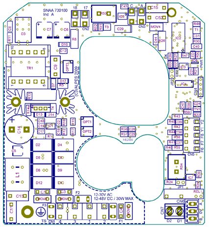
FR FRANÇAIS Index Informations générales.................................................................................................. 3 Description Transport et stockage Maintenance Garantie Retour de marchandises Consignes de sécurité Indicateur de position ................................................................................................... 4 Commande manuelle de secours ................................................................................. 4 Encombrements ............................................................................................................ 5 Branchements électriques ............................................................................................ 6 Avertissements Instructions de câblage Schéma électrique Cartes électroniques Modèles FAILSAFE........................................................................................................ 9 Description Caractéristiques Carte électronique Signification des LEDs Schéma électrique Modèles POSI ................................................................................................................ 11 Description Carte électronique Instructions de câblage Schéma électrique Séquences de paramétrage Modèles 3 positions ...................................................................................................... 14 Description État des contacts Schéma électrique Données techniques...................................................................................................... 15 2 DSBA3200 • Rév. 15/02/2018
FRANÇAIS FR
DESCRIPTION
Ces actionneurs électriques ont été conçus pour permettre le pilotage d’une vanne 1/4 tour. Pour tout autre application, nous consulter
préalablement. Nous ne pouvons être tenus responsables en cas d’autre utilisation.
TRANSPORT ET STOCKAGE
Les transporteurs étant responsables des avaries et des retards de livraison, les destinataires doivent émettre des réserves, le cas
échéant, avant de prendre livraison des marchandises. Les envois directs d’usine sont soumis aux mêmes conditions.
Le transport sur site est effectué dans un emballage rigide.
Les produits doivent être stockés dans des endroits propres, secs et aérés, de préférence sur des palettes de manutention ou sur des
étagères.
MAINTENANCE
La maintenance est assurée par notre usine. Si le matériel ne fonctionne pas, vérifier le câblage suivant le schéma électrique et l’ali-
mentation de l’actionneur électrique concerné.
Pour toute question, prendre contact avec le service après-vente.
Pour nettoyer l’extérieur de l’appareil, utiliser un chiffon (et de l'eau savonneuse). NE PAS UTILISER D'AGENT A BASE DE SOLVANT
OU D'ALCOOL.
GARANTIE
100% des actionneurs ont été testés et réglés en usine.
Ces produits sont garantis 3 ans ou 50000 manœuvres contre tous vices de fabrication et de matière, à partir de la date de livraison
(facteur de service et classe du modèle suivant la norme CEI34).
Cette garantie n'est valable que dans le cas où le matériel aura été, entre temps, ni démonté, ni réparé. Cette garantie ne s'étend pas
à l'usure provoquée par suite de chocs ou maladresse, ainsi que par l'utilisation du matériel dans les conditions qui ne seraient pas
conforme à ses caractéristiques. Cette garantie est strictement limitée au remplacement de la ou des pièces d'origines reconnues dé-
fectueuses, par nos services, après expertise. Les frais de port aller et retour, ainsi que la main d'œuvre, restent à la charge du client.
Aucune responsabilité ne serait nous incomber au sujet des accidents ou risques directs ou indirects découlant d'une défectuosité de
nos matériels. La garantie ne couvre pas les conséquences d'immobilisation et exclut tout versement d'indemnité. Les accessoires et
adaptations ne sont pas couverts par cette garantie. Au cas où le client n'aurait pas réalisé ponctuellement les paiements stipulés aux
échéances convenues, notre garantie sera suspendue jusqu'au paiement des échéances en retard et sans que cette suspension
puisse augmenter la durée de la garantie à la mise à disposition.
RETOUR DE MARCHANDISE
L'acheteur est tenu de vérifier au moment de la livraison la conformité de la marchandise par rapport à sa définition.
L'acceptation par l'acheteur de la marchandise dégage le fournisseur de toute responsabilité, si l'acheteur découvre une non-
conformité postérieurement à la date d'acceptation. Dans un tel cas, les frais de mise en conformité seront à la charge de l'acheteur
qui supportera également seul, les conséquences financières du dommage. Les retours des marchandises sont acceptés que si nous
les avons préalablement autorisés : ils doivent nous parvenir franco de tous frais à domicile et ne comporter que des produits dans leur
emballage d’origine. Les marchandises rendues sont portées au crédit de l'acheteur, déduction faite des 40% de reprise du matériel
calculé sur la base du montant initial des marchandises retournées.
CONSIGNES DE SECURITE A lire avant toute installation du produit
L’alimentation électrique doit être coupée avant toute intervention sur l’actionneur électrique (avant de démonter le capot ou de mani-
puler la commande manuelle de secours).
Toute intervention doit être effectuée par un électricien qualifié ou une personne formée aux règles d’ingénierie électrique, de sécurité
et tout autre directive applicable.
Respecter impérativement l’ordre des consignes de raccordement et de mise en service décrites dans le manuel sans quoi le bon
fonctionnement n’est plus garanti. Vérifier les indications portées sur la plaque d’identification de l’actionneur : elles doivent corres-
pondre à votre réseau électrique d’alimentation.
Ne pas monter l’actionneur « tête en bas ». Risques encourus :
Disfonctionnement du mécanisme de débrayage
Possible écoulement de graisse sur la partie électronique
Ne pas monter l'actionneur à moins de 30 cm d’une source de perturbations électromagnétiques.
Ne pas positionner l'appareil de manière à rendre difficile la manœuvre du dispositif de sectionnement.
DSBA3200 • Rév. 15/02/2018 3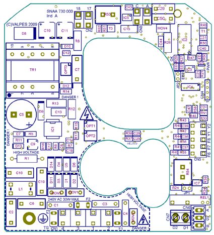
FR FRANÇAIS
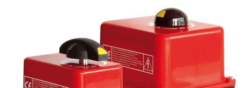
Indicateur de position
Indicateur poignée pour ER10/20 et rond pour ER
35/60/100
Indicateur modulable, livré avec 5 repères de signalisation (3 jaunes + 2
noirs), à positionner en fonction du type de vanne à piloter
Vanne 0° 90° 180°
2 voies :
0° = fermée
90° = ouverte
3 voies (L) :
3 voies (T) :
Ex : T1
Commande manuelle de secours
L’actionneur fonctionne en priorité électrique. S’assurer que l’alimentation est coupée avant de le manœuvrer manuellement
2
1 3
1. Tourner le bouton de débrayage vers la position MAN (sens antihoraire) et le maintenir dans cette position.
2. Tourner l’axe sortant de l’actionneur à l’aide d’une clé à molette.
3. Pour revenir en position automatique, relâcher le bouton de débrayage (rappel par ressort).
4 DSBA3200 • Rév. 15/02/2018
FRANÇAIS FR
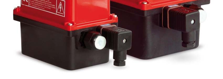
Encombrements
Capot nylon PA6
Indicateur visuel de position Manette commande manuelle de secours
Carter nylon
PA6 FV
Bouton de
débrayage 9
11
Ou / Or
Douille
ER10/20/35
Étoile 14 (mm) Platine F03/F05-F04
Carré / Etoile (mm) Profondeur (mm)
14 16
ER35/60/100
17 19
Étoile 22 (mm)
22 24
Fixation ISO F Diamètre (mm) Taraudé M Profondeur (mm) Nombre de vis
F03 36 M5 14.2 4
F04 42 M5 14.2 4
F05 50 M6 14.2 / 16.4 4
F07 70 M8 16.4 4
DSBA3200 • Rév. 15/02/2018 5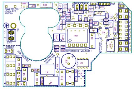
FR FRANÇAIS
Branchements électriques
Avertissements
Terre de Tension
terre Tension continue Tension alternative
protection dangereuse
Le branchement à une prise de terre est obligatoire au-delà de 42V suivant la norme en vigueur.
L'actionneur étant branché en permanence, il doit être raccordé à un dispositif de sectionnement (interrupteur, disjoncteur), assurant la cou-
pure d'alimentation de l’actionneur, placé convenablement, facilement accessible et marqué comme étant le dispositif de coupure de l'ap-
pareil.
Lors de la mise sous tension des actionneurs, un courant d’appel peut-être présent. Il faut donc limiter le nombre d’appareils sur la même
ligne ou utiliser un limiteur de courant d’appel en sortie de disjoncteur.
La température du bornier peut atteindre 90°C
Pour une utilisation avec de grandes longueurs de câbles, le courant induit généré par les câbles ne doit pas dépasser 1mA
Afin d’optimiser la sécurité des installations, le câblage du report défaut (D1 et D2) est fortement conseillé.
Pour assurer une étanchéité IP66, le presse-étoupe destiné à connecter les contacts de recopie doit être utilisé (câble de 7 à 12mm). Dans le cas
contraire, remplacer le presse étoupe par un bouchon ISO M20 IP66.
Instructions
Nos presse-étoupe acceptent un câble de diamètre compris entre 7mm et 12mm.
L'actionneur accepte les surtensions temporaires survenant sur le RÉSEAU d'alimentation jusqu'à ±10 % de la tension nominale.
Il est impératif de raccorder tous les actionneurs à une armoire électrique.
Retirer l’indicateur visuel, dévisser les 4 vis et retirer le capot.
CÂBLAGE DE L’ALIMENTATION ET DE LA COMMANDE
Vérifier sur l’actionneur que la tension indiquée sur l’étiquette correspond à la tension du réseau.
Pour garantir le bon fonctionnement de la résistance anti-condensation, l’actionneur doit être alimenté en permanence
CÂBLAGE DE LA RECOPIE (Sauf POSI : p.11)
Nos actionneurs sont par défaut équipés de 2 contacts de fin de course auxiliaires secs, soit normalement ouverts, soit normalement
fermés (voir schéma électrique DSBL0436). Par défaut, la came blanche est utilisée pour détecter l’ouverture (FC1) et la came noire
pour détecter la fermeture (FC2).
Les fins de courses auxiliaires doivent être connectés avec des câbles rigides. Si la tension appliquée est supérieure à 42V, l'utilisateur doit pré-
voir un fusible dans la ligne d'alimentation.
Les tensions appliquées à chaque contact de recopie (FC1 et FC2, Carte électronique SNAA690000) doivent impérativement être les mêmes.
L’isolation renforcée par rapport au control moteur, autorise des tensions jusqu’à 250V AC/DC.
Dévisser le presse-étoupe droit et passer le câble.
Enlever 25mm de gaine et dénuder chaque fil de 8mm.
Connecter les fils sur le bornier suivant le schéma p.7 (ou p.12 pour les modèles POSI) .
Revisser le presse-étoupe (s’assurer du bon remontage de celui-ci afin de garantir une bonne étanchéité).
REGLAGE DES CONTACTS DE FIN DE COURSE
L’actionneur est préréglé en usine. Ne pas toucher les 2 cames inférieures sous peine de perturber le fonctionnement de l’actionneur
voire d’endommager ce dernier.
Pour ajuster la position des contacts auxiliaires, faire pivoter les 2 cames supérieures en utilisant la clé appropriée.
Remonter le capot, visser les 4 vis et monter l’indicateur visuel.
6 DSBA3200 • Rév. 15/02/2018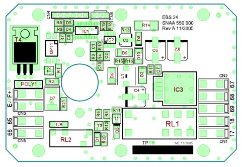
FRANÇAIS                      FR

            La température du bornier peut atteindre 90°C

            REP      DESIGNATION                                                      REP           DESIGNATION
            FC0      Fin de course ouverture                                          FC1           Fin de course auxiliaire 1
            FCF      Fin de course fermeture                                          FC2           Fin de course auxiliaire 2
          D1/D2      Bornier report défaut (24V DC / 3A max)

          ALIMENTATION : CONNECTEUR 3P+T DIN43650                                                                       RECOPIE

                                                                                                       SI OPTION CONNECTEUR (ECD.1A)
                     CABLAGE CLIENT SUGGERE
    Mode 3 points modulants                       Mode Tout ou rien (ON/OFF)
                                                                                                                        ECD.1A
                                                                                                                      Connecteur gris
N                          Ph                     N                            Ph
-                          +                      -                             +                   RECOPIE FC2   COMMUN FC1/FC2             RECOPIE FC1

                                                                                                                                3
                  Ouvrir        Fermer                            Ouvrir                                                    2       1

      TP/PE                                           TP/PE

      1       2                                       1       2                                                                 3
          3                                               3                                                                 2       1

                                                                                                                  4      5          6   7        8   9

                                   1         2                                                       SI CÂBLAGE PAR LE PRESSE-ÉTOUPE
                                        3

                                                                                                    RECOPIE FC1                             COMMUN FC2
                      1                 2             3
                                                                                              COMMUN FC1                                       RECOPIE FC2

    TP/PE                                                                                                         4     5           6   7       8    9
                      15V-30V 50/60Hz (12V-48V DC)
                    100V-240V 50/60Hz (100V-350V DC)              A        A
                                                                  D1
                                                                  D2
                                                                                              FCF
                                                                                FC0

                                                                                                           FC1

                                                                                                                             FC2

                                        17   18       C

                                                                                          ~
                   Mode ON/OFF         Version
                     obligatoire                                                      —       +
                                       Failsafe                                           ~
                                       EBS.24
                                                              M            B                                                                   SNAA690000

    DSBA3200 • Rév. 15/02/2018                                                                                                                               7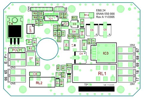
FR         FRANÇAIS

    Cartes électroniques

                                                                SNAA720100                                                 SNAA720000
                                                        15V-30V 50/60Hz (12V-48V DC)                             100V-240V 50/60Hz (100V-350V DC)

                                        G           A                  F        D          E             G       A                    F      D          E
    Cartes d’alimentation et commande
             pour ER 10-20-35

                                            B       C                                                        B       C

                                                                SNAA730100                                                 SNAA730000
                                                        15V-30V 50/60Hz (12V-48V DC)                             100V-240V 50/60Hz (100V-350V DC)

                                                                                               F                                                            F
    Cartes d’alimentation et commande

                                                                                               E                                                            E
            pour ER 35-60-100

                                                                                               D                                                            D

                                                A       C     B    C                   G                     A           C   B    C                 G

                      REP               DESIGNATION                                                REP       DESIGNATION
                            A           Vis de terre                                               E**       LED 3 : défaut détecté
                            B           Bornier alimentation et commande                           F         LED 1 : présence tension
                           *C*          Fusibles protection carte                                  G         Bornier report défaut (24V DC - 3A max)
                            D           LED 2 : microprocesseur ok
    * Fusibles pour carte multi-tensions
      - Carte SNAA720100 : 2A / T 250V (Multicomp MST 2A 250V)
      - Carte SNAA720000 : 500mA / T 250V (Multicomp MST500MA 250V)
      - Carte SNAA730100 : 5A / T 125V (Littelfuse 39615000000)
      - Carte SNAA730000 : 3,15A / T 250V (Multicomp MST 3,15A 250V)

    ** Défauts possibles : limitation de courant, limitation thermique ou erreur programme
       => vérifier que le couple de la vanne n’est pas supérieur au couple maximum fourni par l’actionneur
       => vérifier que l’actionneur ne dépasse pas la durée sous tension donnée (surchauffe possible)
       Pour redémarrer l’actionneur, inverser le sens de marche ou l’éteindre et le remettre sous tension.

8                                                                                                                                DSBA3200 • Rév. 15/02/2018
FRANÇAIS                FR

Modèles FAILSAFE
       En cas de coupure de courant, 3 minutes sont nécessaires pour que la fonction Failsafe soit de nouveau opérationnelle.

Actionneurs avec système de sécurité intégré (mode Tout ou Rien obligatoire)
Le modèle failsafe intègre un bloc batterie de secours piloté par une carte électronique. Sa fonction est de prendre le
relais en cas de coupure d’alimentation aux bornes 1, 2 et 3 de l’actionneur. Le modèle failsafe peut être configuré en
normalement ouvert (NO) ou normalement fermé (NF) selon l’application client.
La carte pilotant la batterie gère le cycle de charge et vérifie l’état de la batterie. Si un défaut est détecté au niveau de la
batterie, un contact sec entre les bornes 65 et 66 s’ouvre. Si ce contact est relayé par le client, il a ainsi la possibilité de
détecter un défaut sans ouvrir l’actionneur et de prévoir le remplacement de la batterie.
Le modèle failsafe fonctionne en câblage ON/OFF.

Carte électronique chargeur
                                                   D         E

                               B

                               C                                                                         A

                                                                       REP   DESIGNATION
Tension                                18V DC                          A     Connecteur 18V DC
Courant nominal                        0,8A
                                                                       B     Connecteur bloc batterie
Courant maximal                        2,4A
                                                                       C     Connecteur report d’état (défaut de charge/batterie)
Durée initiale de charge               14h max
Relais de report d’état de la charge   24V DC - 1A max                 D     LED verte
Température                            -10°C à 40°C                     E    LED rouge

Signification des LEDs
               LED                 LED verte           LED rouge

                                                       Clignote/éteinte/
                                   Éteinte                                   Batterie déconnectée ou hors service
                                                       clignote...

                                   Allumée             Clignote              Cycle de charge de la batterie en cours (max 14h)

                                   Allumée             Éteinte               Cycle de charge terminé

                                   Clignote vite       Éteinte               Alimentation de l'actionneur pendant 3mn (mise en sécurité)

                                   Éteinte             Clignote vite         Erreur du microcontrôleur

DSBA3200 • Rév. 15/02/2018                                                                                                          9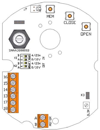
FR          FRANÇAIS

                                         BLOC BATTERIE

     E- : fil noir                          Bloc de sécurité                       Carte alimentation et commande
                              F+
     F+ : fil rouge                                                                                                       D1
                              E-                                                                                         D2
                                                                   17   17
                                                                                 100V-240V 50/60Hz (100V-350V DC)
                                                                                   15V-30V 50/60Hz (24V-48V DC)
                              65                                   18   18
     REPORT D’ETAT DE LA
                                         Batterie chargée : con-
          CHARGE                                tact fermé
                              66

      CABLAGE ACTIONNEUR
                                                                             1      2        3         1    2        3

     CABLAGE CLIENT SUGGERE

                                                                                    Ouvrir                  Fermer

                                                                             N               Ph        N         Ph

                                                                             GS2                      GS2.O
                                                                        Fermé par défaut              Ouvert par défaut

                                                                                        Mode Tout ou rien

          Les modes de fonctionnement « fermé par défaut » et ouvert par défaut » correspondent à deux produits
          différents (paramétrés en usine) et ne sont pas interchangeables.

10                                                                                                DSBA3200 • Rév. 15/02/2018
FRANÇAIS FR
Modèles POSI
Différents types de consigne (pilotage carte Bornier N°15 et N°16)
Nos cartes sont paramétrables en usine sur demande. Le signal de commande (consigne) et signal de recopie peuvent être de nature
différente (courant ou tension). Sans aucune information du client les cartes sont paramétrées en courant 4-20mA (consigne + recopie
client)
Pilotage en 0-10V et 0-20mA :
Lors d’un événement extérieur, absence de consigne (coupure accidentelle du câble par ex) mais en présence de l’alimentation carte.
La convention veut que l’actionneur se retrouve en une position définie (vanne ouverte ou fermée). En standard nos actionneurs se
fermeront en absence de consigne, mais d’autres états sont possibles sur demande
Pilotage en 4-20mA.
La convention veut que l’actionneur reste dans sa position lors de la coupure de la consigne (coupure accidentelle du câble par ex)
mais en présence de l’alimentation carte.
Lors du rétablissement de la consigne l’actionneur se repositionne automatiquement selon la valeur de la consigne
Carte électronique de positionnement P6 (0-20mA / 4-20mA / 0-10V)
N D REP DESIGNATION
A Bornier d’alimentation 24V AC/DC
E B Bornier de consigne
F C Bornier de recopie
L D Bouton de réglage MEM
E Bouton de réglage CLOSE
G F Bouton de réglage OPEN
H J G Cavalier K1
H Cavalier K2
B K I Cavalier K3
J LEDs verte et rouge
C
I K LED jaune : présence tension
A L Potentiomètre
M Connexion moteur
M N Connecteur résistance de réchauffage
Actionneur déjà préréglé en usine
Câblage consigne et recopie de la carte P6
Afin de limiter les perturbations électromagnétiques, l’utilisation de câbles blindés est obligatoire (câbles supérieurs à 3m).
Dévisser le presse-étoupe et passer le câble.
Connecter la consigne entre les bornes 15 et 16
La borne 15 est la polarité négative (-) et la borne 16 la polarité positive (+).
Connecter la recopie entre les bornes 13 et 14
La borne 13 est la polarité positive (+) et la borne 14 la polarité négative (-).
Revisser le presse-étoupe (s’assurer du bon remontage de celui-ci afin de garantir une bonne étanchéité).
Montage départ usine : par défaut, consigne et recopie en 4-20mA, sens normal.
Pour reparamétrer la carte : voir page 13, « Séquence de paramétrage ».
Pour vérifier le bon fonctionnement de la carte : voir page 13, « Mode de fonctionnement normal ».
DSBA3200 • Rév. 15/02/2018 11FR FRANÇAIS
RECOPIE
ALIMENTATION : CONNECTEUR 3P+T DIN43650
COMMUN FC1
COMMUN FC2
N Ph
- TP/PE +
RECOPIE FC1
RECOPIE FC2
1 2
3
1 2
3 4 5 6 7 8 9
1 2 3
D1
FCF
FC0
FC1
FC2
D2
15V-30V 50/60Hz (12V-48V DC)
100V-240V 50/60Hz (100V-350V DC)
~
— +
TP/PE
17 18 ~
17 18 SNAA690000
A B
A
C Motor
P6 =
SNAA380000
POSI
REP DESIGNATION
FC0 Fin de course ouverture
13 14 15 16
FCF Fin de course fermeture
+ – – + FC1 Fin de course auxiliaire 1
RECOPIE CONSIGNE FC2 Fin de course auxiliaire 2
D1/D2 Bornier report défaut (24V DC / 3A max)
0-20mA / 4-20mA / 0-10V
La résolution de la carte est de 1°
Impédance d’entrée de 10 kOhm si pilotage en tension (0-10V)
Impédance d’entrée de 100 Ohm si pilotage en courant (0-20mA ou 4-20mA)
La tension de pilotage doit être de type T.B.T.S. (Très Basse Tension de Sécurité)
La température du bornier peut atteindre 90°C
La recopie doit être connecté avec des câbles rigides. Si la tension appliquée est supérieure à 42V, l'utilisateur doit prévoir un fusible
dans la ligne d'alimentation.
Pour une utilisation avec de grandes longueurs de câbles, le courant induit généré par les câbles ne doit pas dépasser 1mA
Les câbles utilisés doivent être rigides (tensions pour la recopie : 4 à 250V AC/DC)
12 DSBA3200 • Rév. 15/02/2018FRANÇAIS FR
SEQUENCES DE PARAMETRAGE
1 Positionnement des cavaliers K1, K2 et K3
Positionner les cavaliers d’après le tableau suivant (avant chaque modification, mettre la carte hors ten-
sion) :
Cavalier K1 Cavalier K2
Consigne Recopie Cavalier K3
A B A B
0-10V 0-10V ON OFF ON OFF OFF
0-10V 0-20mA ON OFF OFF ON OFF
0-10V 4-20mA ON OFF OFF ON ON
0-20mA 0-10V OFF ON ON OFF OFF
0-20mA 0-20mA OFF ON OFF ON OFF
0-20mA 4-20mA OFF ON OFF ON ON
4-20mA 0-10v OFF ON ON OFF OFF
4-20mA 0-20mA OFF ON OFF ON OFF
K3 OFF K3 ON 4-20mA 4-20mA OFF ON OFF ON ON
2 Choix du sens de la vanne
2.1 Sens normal (par défaut)
Appuyer sur OPEN et mettre la carte sous tension en maintenant le bouton enfoncé.
G
La LED verte s’allume. Relâcher le bouton OPEN.
Débrancher la carte.
2.2 Sens inverse
Appuyer sur CLOSE et mettre la carte sous tension en maintenant le bouton enfoncé.
R La LED rouge s’allume. Relâcher le bouton CLOSE.
Débrancher la carte.
3 Choix du type de consigne
3.1 Consigne en tension 0-10V
Appuyer sur MEM et mettre la carte sous tension en maintenant le bouton enfoncé.
La LED rouge clignote 3 fois. Relâcher le bouton.
R
Débrancher la carte.
3.2 Consigne en courant 0-20mA
Appuyer sur MEM et OPEN et mettre la carte sous tension en maintenant les boutons enfoncés.
R La LED rouge clignote 3 fois. Relâcher les boutons.
Débrancher la carte.
3.3 Consigne en courant 4-20mA (par défaut)
Appuyer sur MEM et CLOSE et mettre la carte sous tension en maintenant les boutons enfoncés.
R La LED rouge clignote 3 fois. Relâcher les boutons.
Débrancher la carte.
G R 4 Mode apprentissage
Appuyer sur OPEN et CLOSE et mettre la carte sous tension en maintenant les boutons enfoncés.
R Les 2 LEDs s’allument. Relâcher les boutons, les 2 LEDs s’éteignent. Le mode apprentissage est
sélectionné.
R Appuyer sur CLOSE pour faire venir la vanne en position fermée. La LED rouge s’allume.
Mémoriser la position fermée par MEM + CLOSE, la LED rouge clignote 2 fois pour acquitter.
Appuyer sur OPEN pour faire venir la vanne en position ouverte. La LED verte s’allume.
G
Mémoriser la position ouverte par MEM + OPEN, la LED verte clignote 2 fois pour acquitter.
Les positions sont mémorisées, débrancher la carte.
G
MODE DE FONCTIONNEMENT NORMAL
Mettre la carte sous tension. La LED verte clignote 3 fois.
Lors du fonctionnement normal, la LED verte s’allume lorsque le moteur ouvre la vanne, et la LED
G rouge lorsque le moteur ferme la vanne.
Lorsque les 2 LEDs sont éteintes, le moteur n’est pas sollicité.
G R
En cas de couple trop important, les 2 LEDs s’allument pour indiquer la limitation et l’actionneur s’arrête.
Pour le redémarrer, il faut soit inverser le sens de marche, soit éteindre et remettre sous tension la carte.
DSBA3200 • Rév. 15/02/2018 13FR FRANÇAIS
Modèles 3 positions
Actionneur avec possibilité d’une troisième position
L’option GF3 permet à l’actionneur d’être piloté en 3 positions. Les trois positions peuvent être comprises entre 0° et 180°. En stan-
dard les actionneurs sont réglés en usine à 0° | 90° | 180°, ce qui correspond à une vanne 3 voies standard. D’autres configurations
sont possibles mais cela doit être précisé par le client lors de la commande.
Les 3 positions sont pilotées par 4 contacts (FCO,FCF,FCIO,FCIF) et 3 contacts de recopie (FC1,FC2,FC3)
Les contacts FC1,FC2 sont des contacts NO (fermeture du circuit en position extrême) et FC3 est un contact NF. (ouverture du circuit
en position intermédiaire).
La température du bornier
ALIMENTATION
peut atteindre 90°C
N/- Ph / +
O F I RECOPIE
1 2 3 4
COMMUN FC1
COMMUN FC2
COMMUN FC3
D1
15V-30V 50/60Hz (12V-48V DC)
D2
100V-240V 50/60Hz (100V-350V DC)
TP/PE
RECOPIE FC1
RECOPIE FC2
RECOPIE FC3
M C
A
F6 F7 F8
R B N
F6 F7 F8 4 8 6 9 F4 F9
A
FCIO
FCIF
FC1
FC2
FCF
FC3
FC0
~
— +
~
B
SNAA710000
Bornes REP DESIGNATION REP DESIGNATION
6&9 4&8 F4 & F9 FCO Fin de course ouverture FC1 Fin de course auxiliaire 1
0° Fermé Ouvert Fermé FCF Fin de course fermeture FC2 Fin de course auxiliaire 2
inter Ouvert Ouvert Ouvert Fin de course intermédiaire
FCIO FC3 Fin de course auxiliaire 3
ouverture
180° Ouvert Fermé Fermé
Fin de course intermédiaire Bornier report défaut (24V
FCIF D1/D2
fermeture DC / 3A max)
14 DSBA3200 • Rév. 15/02/2018FRANÇAIS FR
DONNEES TECHNIQUES
Type (actionneur électrique 1/4 tour) ER10 ER20 ER35 ER35 ER60 ER100
Type d’enveloppe Petite enveloppe (voir p.5) grosse enveloppe (voir p.5)
IP66
Protection IP (EN60529)
Étanche aux poussières, jet d’eaux (débitUK ENGLISH Index General information ....................................................................................................... 17 Description Transport and storage Maintenance Warranty Return of goods Safety instructions Position indicator .......................................................................................................... 18 Emergency manual override ......................................................................................... 18 Dimensions .................................................................................................................... 19 Electric wiring ................................................................................................................ 20 Warnings Wiring Instructions Electric diagram Electronic boards FAILSAFE models.......................................................................................................... 23 Description Specifications Electronic board LED meaning Electric diagram POSI models .................................................................................................................. 25 Description Electronic board Wiring Instructions Electric diagram Parameter selection sequence 3-position models.......................................................................................................... 28 Description Contacts state Electric diagram Technical data ............................................................................................................... 29 16 DSBA3200 • Rév. 15/02/2018
ENGLISH UK
DESCRIPTION
These electric actuators have been designed to perform the control of a valve with 90° rotation. Please consult us for any different appli-
cation. We cannot be held responsible if the mentioned actuators are used in contradiction to this advice..
TRANSPORT AND STORAGE
The forwarding agents being held as responsible for damages and delays of the delivered goods, the consignees are obliged to ex-
press if applicable their reserves, prior to accept the goods. The goods delivered directly ex works are subject to the same conditions.
The transport to the place of destination is carried out by using rigid packing material.
The products must be stored in clean, dry, and ventilated places preferably on appropriate palettes or shelves.
MAINTENANCE
Maintenance is ensured by our factory. If the supplied unit does not work, please check the wiring according to the electric diagram as
well as the power supply of the concerned electric actuator.
For any question, please contact our after-sales service.
To clean the outside of the actuator, use a lint and soapy water. DO NOT USE CLEANING PRODUCT WITH SOLVENT OR ALCOHOL
WARRANTY
100% of the actuators are fully tested and set in the factory.
These products are 3-year warranty from the delivery date or 50,000 actuations against all types of manufacturing and material faults
(operating time and model class according to standard CEI34).
This guarantee will only be valid if the unit has not been disassembled or self-repaired during its service life. It does not cover any wear
and damage caused by shocks or faulty operation neither by the use of the unit under conditions not in accordance with its nominal
characteristics. The guarantee is strictly limited to the replacement of original parts found defective on checking by our service person-
nel. The cost of shipping to our premises, the return of devices to the customer as well as the repair cost will be chargeable. We will
not assume the responsibility for any direct or indirect accidents/risks originated by a failure of our products. The guarantee does not
cover the consequences of breakdown and excludes any payments for indemnities. The accessories and adaptations are excluded
from the guarantee. In the case where a customer has not proceeded to payments within the agreed period, our guarantee will be
suspended until the delayed payments have been received and with the consequence that this suspension will not prolong the guaran-
tee period in any case.
RETURN OF GOODS
The customer is obliged to check the conformity of the goods with regard to their definition at the time of delivery.
The acceptance of the goods by the purchaser disclaims the supplier of all responsibility if the purchaser discovers any non-conformity
after the date of acceptance. In such case, the repair cost will be borne by the purchaser who will also exclusively bear all financial
consequences of any resulting damage. Returned goods will only be accepted if our prior agreement has been given to this proce-
dure : the goods must be sent free of all cost and being shipped solely and in their original packing. The returned goods will be credit-
ed to the purchaser with a reduction of 40% on the unit’s price charged in accordance with the original invoice of the returned goods.
SAFETY INSTRUCTIONS To be read prior to the installation of the product
The electric power supply must be switched-off before any intervention on the electric actuator (i.e. prior demounting its cover or ma-
nipulating the manual override knob).
Any intervention must only be carried out by a qualified electrician or other person instructed in accordance with the regulations of
electric engineering, safety, and all other applicable directives.
Strictly observe the wiring and set-up instructions as described in the manual: otherwise, the proper working of the actuator can not be
guaranteed anymore. Verify that the indications given on the identification label of the actuator fully correspond to the characteristics of
the electric supply.
Do not mount the actuator « upside down ». Risks:
Declutching mechanism failure
Possible flow of the grease on the electronic board
Do not mount the actuator less than 30 cm of a electromagnetic disturbances source.
Do not position the equipment so that it is difficult to operate the disconnecting device.
DSBA3200 • Rév. 15/02/2018 17UK ENGLISH
Position indicator
Handle with position indicator for ER10/20 and
round indicator for ER 35/60/100
Modular position indicator with three removable position markers (3 yellow +
2 black), adjustable according the type of valve to be actuated
Valve 0° 90° 180°
2-way:
0° = close
90° = open
3-way (L):
3-way (T):
Ex : T1
Emergency manual override
The priority functioning mode of this actuator is electric. Be sure than the power supply is switched off before using the manual
override
2
1 3
1. Turn the knob to position MAN (counter-clockwise) and hold it in position.
2. Turn the outgoing drive shaft of the actuator with the help of an adjusting spanner.
3. In order to re-engage the reduction, release the knob (spring return).
18 DSBA3200 • Rév. 15/02/2018ENGLISH UK
Dimensions
Nylon PA6 cover
Visual position indicator Handle for manual override
Nylon GF
PA6 Housing
Clutch
knob 9
11
Ou / Or
Sleeve
ER10/20/35
Star 14 (mm) F03/F05-F04 plate
Square / Star (mm) Depth (mm)
14 16
ER35/60/100
17 19
Star 22 (mm)
22 24
ISO F flange Diameter (mm) M threaded Depth (mm) Screws quantity
F03 36 M5 14.2 4
F04 42 M5 14.2 4
F05 50 M6 14.2 / 16.4 4
F07 70 M8 16.4 4
DSBA3200 • Rév. 15/02/2018 19UK ENGLISH
Electric wiring
Warnings
Protective Dangerous
Ground Direct voltage Alternating voltage
earthing voltage
As stipulated in the applicable regulation, the connection to earth contact is compulsory for devices with working voltages exceeding 42V.
The actuator is always powered, so it must be connected to a disconnection system (switch, circuit breaker) to ensure the actuator power
cut, correctly located, easily reached and marked as being the disconnecting device for the equipment.
An Inrush current may occur when actuators are switched on. Therefore it is necessary to limit the number of actuators on the same line.
Alternatively an inrush current limiter at the output of the circuit breaker may be used.
The terminal temperature can reach 90°C
For a use with a long power supply wiring, the induction current generated by the wires mustn't be higher than 1mA
To optimize the installation security, please connect the failure feedback signal (D1 and D2).
In order to ensure the IP66 tightness, the cable gland for feedback wiring must be used (7 to 12mm cable). Otherwise, the cable
gland must be replaced by a ISO M20 IP66 cap.
Instructions
Our cable glands are designed for cables with a diameter between 7mm and 12mm.
The actuator can support MAINS supply voltage fluctuations up to ±10 % of the nominal voltage.
It is necessary to connect all actuators to an electrical cabinet
Remove the position indicator, unscrew the four screws and take off the cover.
SUPPLY AND CONTROL WIRING
Ensure that the voltage indicated on the actuator ID label corresponds to the voltage supply.
Connect the wires to the connector in accordance with the required control mode. (see diagram p.21 or p.26 for POSI models )
To ensure the correct functioning of the anti-condensation heaters, the actuator must be permanently power supplied
WIRING OF THE FEEDBACK SIGNAL (Except POSI: p.25)
Our actuators are equipped with two simple limit switch contacts normally set either in open position, either in closed position (see wir-
ing diagram DSBA0436). As per factory setting, the white cam is used to detect the open position (FC1) and the black cam is used to
detect the closed position (FC2).
The auxiliary limit switches must be connect with rigid wires. If the applied voltage is higher than 42V, the user must foresee a fuse in
the power supply line.
The voltages applied to each feedback switch (FC1 and FC2, SNAA690000 electronic board) must be exactly the same .The reinforced
insulation between the feedback signal and the motor control authorizes voltages up to 250V AC/DC.
Unscrew the right cable gland and insert the cable.
Remove 25mm of the cable sheath and strip each wire by 8mm.
Connect the wires to the terminal strip in accordance with the diagram p.21 (or p.26 for POSI models ).
Tighten the cable gland (Ensure that it’s well mounted to guaranty the proofness).
SETTING OF END LIMIT SWITCHES
The actuator is pre-set in our factory. Do not touch the two lower cams in order to avoid any malfunctioning or even damage to the
actuator.
To adjust the position of the auxiliary contacts, make rotate the two superior cams by using the appropriate wrench.
Re-mount the cover, fasten the four screws and attach the position indicator.
20 DSBA3200 • Rév. 15/02/2018ENGLISH UK
The terminal temperature can reach 90°C
The used wires must be rigid (feedback voltages : 4 to 250V AC/DC)
REP DESIGNATION
FCO Open limit switch FC1 Auxiliary limit switch 1
FCF Close limit switch FC2 Auxiliary limit switch 2
D1/D2 Failure report Terminal strip (24V DC / 3A max)
POWER SUPPLY : 3P+T DIN43650 CONNECTOR FEEDBACK
IF CONNECTOR OPTION (ECD.1A)
SUGGESTED CUSTOMER WIRING
Modulating 3-point control On-off control
ECD.1A
Grey connector
N Ph N Ph
- + - + FEEDBACK FC2 COMMON FC1/FC2 FEEDBACK FC1
3
Open Close Open 2 1
TP/PE TP/PE
1 2 1 2 3
3 3 2 1
4 5 6 7 8 9
1 2 IF WIRING TROUGH THE CABLE GLAND
3
FEEDBACK FC1 COMMON FC2
1 2 3
COMMON FC1 FEEDBACK FC2
TP/PE 4 5 6 7 8 9
15V-30V 50/60Hz (12V-48V DC)
100V-240V 50/60Hz (100V-350V DC) A A
D1
D2
FCF
FC0
FC1
FC2
17 18 C
~
ON/OFF control Failsafe — +
compulsory version ~
EBS.24
M B SNAA690000
DSBA3200 • Rév. 15/02/2018 21UK ENGLISH
Electronic boards
SNAA720100 SNAA720000
15V-30V 50/60Hz (12V-48V DC) 100V-240V 50/60Hz (100V-350V DC)
G A F D E G A F D E
Power supply and Control boards
for ER 10-20-35
B C B C
SNAA730100 SNAA730000
15V-30V 50/60Hz (12V-48V DC) 100V-240V 50/60Hz (100V-350V DC)
F F
Power supply and Control boards
E E
for ER 35-60-100
D D
A C B C G A C B C G
REP DESIGNATION REP DESIGNATION
A Earth screw E** LED 3 : detected failure
B Power supply and control terminal F LED 1 : power supply presence
*C* Protection fuses G Failure report terminal strip (24V DC - 3A max)
D LED 2 : microprocessor ok
* Fuses for multivolt boards
- SNAA720100 board: 2A / T 250V (Multicomp MST 2A 250V)
- SNAA720000 board: 500mA / T 250V (Multicomp MST500MA 250V)
- SNAA730100 board: 5A / T 125V (Littelfuse 39615000000)
- SNAA730000 board: 3,15A / T 250V (Multicomp MST 3,15A 250V)
** Possible defects : limitation of current, thermic limitation or program error
=> check that the valve torque is not superior to the maximum torque stand by the actuator
=> check that the actuator do not exceed the duty cycle indicated (possible overheat)
To re-start the actuator, reverse the sense of rotation or switch the power off and on.
22 DSBA3200 • Rév. 15/02/2018ENGLISH UK
FAILSAFE model
Following a power failure, the Failsafe unit will reset after 3 minutes.
Actuator with failsafe integrated security system (ON/OFF mode compulsory)
Failsafe model integrate a battery pack monitored by an electronic board inside the actuator. Its function is to relay in
case of power supply failure on terminal PIN 1,2 and 3 of the actuator. The failsafe system can be set on different posi-
tion like normally open (NO) or normally closed (NC). It depends on customer application.
The electronic board monitors the battery pack and check the status of battery (cycle load and failure)
If a battery failure is detected , a contact on PIN 65 and 66 switch off. If customer use this contact he could be aware
that there is a failure on battery in the actuator without remove cover and plan the replacement.
Fail safe option required ON/OFF mode.
Loading electronic board
D E
B
C A
REP DESIGNATION
Voltage 18V DC A 18V DC terminal strip
Nominal current 0,8A
B Block battery terminal strip
Courant maximal 2,4A
C State feedback terminal strip (load or battery failure)
Initial loading time 14h max
Load state feedback relay 24V DC - 1A max D Green LED
Temperature -10°C to 40°C E Red LED
LED meaning
LED Green LED Red LED
Off Blinks/off/Blinks... Battery disconnected or out of service
On Blinks Battery loading cycle in progress (max 14h)
On Off Battery loading cycle finished
Blinks rapidly Off Actuator electrical supply during 3 minutes (failure mode)
Off Blinks rapidly Microcontroller failure
DSBA3200 • Rév. 15/02/2018 23UK ENGLISH
BATTERY BLOCK
E-: black wire Security block Power supply and control board
F+
F+: red wire D1
E- D2
17 17
100V-240V 50/60Hz (100V-350V DC)
15V-30V 50/60Hz (24V-48V DC)
65 18 18
LOAD STATE
Loaded battery : closed
FEEDBACK contact
66
ACTUATOR WIRING
1 2 3 1 2 3
SUGGESTED CUSTOMER WIRING
Open Close
N Ph N Ph
GS2 GS2.O
Preset to closed Preset to open
On-off control
Both functioning modes « preset to closed » and « preset to open » are two different products (pre-set in fac-
tory) and can’t be interchangeable.
24 DSBA3200 • Rév. 15/02/2018ENGLISH UK
POSI model
Various control types (control signal on terminals N°15 and N°16)
On request, our cards can be set in factory. The consign and the feedback signal can have different forms (current or voltage).
Without any information from the customer, the cards are set for current 4-20mA (control + feedback signal)
Control in modes 0-10V and 0-20mA
In case of outside event, absence of control signal (accidental wires cut for example) but in presence of power, the actuator will travel
to defined position (open or closed valve).
In standard our actuators will close themselves in absence of control signal but there are other possibilities on request.
Control in mode 4-20mA
In case of outside event, absence of control signal (accidental wires cut for example) but in presence of power, the actuator will stay in
its position.
In the both cases, when the control signal is restored, the actuator reach automatically the position corresponding to control signal
value.
P6 positioning electronic board (0-20mA / 4-20mA / 0-10V)
N D REP DESIGNATION
A 24V AC/DC power supply terminal trip
E B Setpoint signal terminal trip
F C Feedback signal terminal trip
L D Adjustment button MEM
E Adjustment button CLOSE
G F Adjustment button OPEN
H J G K1 shunt
H K2 shunt
B K I K3 shunt
J Green and red LEDs
C
I K Yellow LED : power supply indication
A L Potentiometer
M Motor connexion
M N Heating resistor connector
Actionneur déjà préréglé en usine
P6 positioning board wiring (input and output signal)
In order to avoid electromagnetic perturbations, it is compulsory to use shielded cables (cables longer than 3m).
Unscrew the gland and pass the cable.
Connect the setpoint signal between terminals 15 and 16.
Terminal 15 is the negative polarity (-) and terminal 16 is the positive polarity (+).
Connect the feedback signal between terminals 13 and 14.
Terminal 13 is the positive polarity (+) and terminal 14 is the negative polarity (-).
Tighten the cable gland (Ensure that it’s well mounted to guaranty the proofness).
Factory setting : by default, 4-20mA input and output signals with normal rotation direction.
To proceed to a new setting of the card : please see page 27, “Parameter selection sequence”.
To check the proper operation of the card : please see page 27, “Normal operating mode”.
DSBA3200 • Rév. 15/02/2018 25UK ENGLISH
FEEDBACK
POWER SUPPLY : 3P+T DIN43650 CONNECTOR
COMMON FC1
COMMON FC2
N Ph
- TP/PE +
FEEDBACK FC2
FEEDBACK FC1
1 2
3
1 2
3 4 5 6 7 8 9
1 2 3
D1
FCF
FC0
FC1
FC2
D2
15V-30V 50/60Hz (12V-48V DC)
100V-240V 50/60Hz (100V-350V DC)
~
— +
TP/PE
17 18 ~
17 18 SNAA690000
A B
A
C Motor
P6 =
SNAA380000
POSI
REP DESIGNATION
FC0 Open limit switch
13 14 15 16
FCF Close limit switch
+ – – + FC1 Auxiliary limit switch 1
FEEDBACK SETPOINT FC2 Auxiliary limit switch 2
SIGNAL SIGNAL
D1/D2 Failure report Terminal strip (24V DC / 3A max)
0-20mA / 4-20mA / 0-10V
The card resolution is 1°
10 kOhm input impedance if control with voltage (0-10V)
100 Ohm input impedance if control with current (0-20mA ou 4-20mA)
The control voltage must be S.E.L.V. (Safety Extra Low Voltage).
The terminal temperature can reach 90°C.
The feedback must be connect with rigid wires. If the applied voltage is higher than 42V, the user must foresee a fuse in the
power supply line.
For a use with a long power supply wiring, the induction current generated by the wires mustn't be higher than 1mA.
The used wires must be rigid (feedback voltages: 4 to 250V AC/DC).
26 DSBA3200 • Rév. 15/02/2018ENGLISH UK
PARAMETER SELECTION SEQUENCE
1 K1, K2 and K3 shunts positioning
Position the shunts as follows (before modification, switch off the card):
Setpoint Feedback Shunt K1 Shunt K2
Shunt K3
signal signal A B A B
0-10V 0-10V ON OFF ON OFF OFF
0-10V 0-20mA ON OFF OFF ON OFF
0-10V 4-20mA ON OFF OFF ON ON
0-20mA 0-10V OFF ON ON OFF OFF
0-20mA 0-20mA OFF ON OFF ON OFF
0-20mA 4-20mA OFF ON OFF ON ON
4-20mA 0-10v OFF ON ON OFF OFF
4-20mA 0-20mA OFF ON OFF ON OFF
4-20mA 4-20mA OFF ON OFF ON ON
K3 OFF K3 ON 2 Selection of the flow direction of the valve
2.1 Normal flow direction (by default)
Press the OPEN button and apply the operating voltage to the card while keeping this button
G
pressed.
The green LED lights up. Release the OPEN button.
Disconnect the card.
2.2 Inverse flow direction
Press the CLOSE button and apply the operating voltage to the card while keeping this button
pressed.
R
The red LED lights up. Release the CLOSE button.
Disconnect the card.
3 Selection of the type of input control signal
3.1 Voltage control signal 0-10V
Press the MEM button and apply the operating voltage to the card while keeping this button
pressed.
R The red LED will light up 3 times. Release this button.
Disconnect the card.
3.2 Current control signal 0-20mA
Press the MEM and OPEN buttons and apply the operating voltage to the card while keeping these
buttons pressed.
R The red LED will light up 3 times. Release these buttons.
Disconnect the card.
3.3 Current control signal 4-20mA (by default)
Press the MEM and CLOSE buttons and apply the operating voltage to the card while keeping these
buttons pressed.
R
The red LED will light up 3 times. Release these buttons.
Disconnect the card.
4 Learning mode
G R Press the OPEN and CLOSE buttons and apply the operating voltage to the card while keeping
these buttons pressed.
R
The 2 LEDs will light up. Release these buttons and the 2 LEDs will run out. The card is now in the
learning mode.
Press the CLOSE button to put the valve in its closed position. The red LED will light up.
R Store this selected closed position by pushing MEM + CLOSE, the red LED will light up 2 times as a
confirmation of acknowledgement.
Press the OPEN button to put the valve in its open position. The green LED will light up.
G
Store this selected open position by pushing MEM + OPEN, the green LED will light up 2 times as a
confirmation of acknowledgement.
G Now, the positions selected have been stored. Disconnect the card.
NORMAL OPERATING MODE
Apply the operating voltage to the card. The green LED will light up 3 times.
Under normal operating conditions, the green LED will light up when the drive motor opens the
G
valve, and the red LED will light up when the drive motor closes it.
If both LEDs remain ran out, it means that the drive motor has not been triggered.
In the case of an over torque, the motor stops and the 2 LEDS lights then together to indicate the action
G R of the torque limiter. To re-start it, you must either reverse the sense of rotation, either switch the power
off and on.
DSBA3200 • Rév. 15/02/2018 27UK ENGLISH
3-position model
Actuator with a third position
GF3 option allow actuator to be drive and stop in 3 positions. These 3 positions could be between 0° to 180°.In standard actuators
are setting in our workshop at 0° 90° 180° that’s fit with standard 3 ways ball valve. Others positions still available but customer have
to price on the order witch position is request.
These 3 positions are controlled by 4 switches (FCO,FCF,FCIO and FCIF) and 3 switches for feed back signal
Switches FC1,FC2 are NO contact ( close the circuit in extreme position) and FC3 is a NC contact (open the circuit in intermediate
position)
The terminal temperature
POWER SUPPY
can reach 90°C
N/- Ph / +
O F I FEEDBACK
1 2 3 4
COMMON FC1
COMMON FC2
COMMON FC3
D1
15V-30V 50/60Hz (12V-48V DC)
D2
100V-240V 50/60Hz (100V-350V DC)
FEEDBACK FC1
FEEDBACK FC2
FEEDBACK FC3
TP/PE
M C
A
F6 F7 F8
R B N
F6 F7 F8 4 8 6 9 F4 F9
A
FCIO
FCIF
FC1
FC2
FCF
FC3
FC0
~
— +
~
B
SNAA710000
Terminals REP DESIGNATION REP DESIGNATION
6&9 4&8 F4 & F9 FCO Open limit switch FC1 Auxiliary limit switch 1
0° Closed Open Closed FCF Close limit switch FC2 Auxiliary limit switch 2
inter Open Open Open FCIO Intermediate open limit switch FC3 Auxiliary limit switch 3
180° Open Closed Closed Failure report Terminal strip
FCIF Intermediate close limit switch D1/D2
(24V DC / 3A max)
28 DSBA3200 • Rév. 15/02/2018ENGLISH UK
TECHNICAL DATA
Type (1/4 turn electric actuator) ER10 ER20 ER35 ER35 ER60 ER100
Housing type Small housing (see p.19) large housing (see p.19)
IP66
IP protection (EN60529)
(dusts, water spraying « flowD DEUTSCH Index Allgemeine Information ................................................................................................ 31 Beschreibung Transport und Lagerung Wartung Garantie Rücksendung von Waren Anleitung und Sicherheitshinweise Stellungsanzeige ........................................................................................................... 32 Handnotbetätigung........................................................................................................ 32 Dimensionen .................................................................................................................. 33 Elektrische Verbindung ................................................................................................. 34 Warnungen Verkabelung Anweisungen Schaltplan Elektronische Karten FAILSAFE Modele ......................................................................................................... 37 Beschreibung Eigenschaften Elektronische Karte Bedeutung der LED’s Schaltplan POSI Modele ................................................................................................................. 39 Beschreibung Elektronische Karte Verkabelung Anweisungen Schaltplan Parametrisierungsschritte 3 positionen Modele ..................................................................................................... 42 Beschreibung Zustand der Mikroschalter Schaltplan Technischen Daten........................................................................................................ 43 30 DSBA3200 • Rév. 15/02/2018
DEUTSCH D
BESCHREIBUNG
Die elektrischen Stellantriebe wurden entwickelt, um Ventile mit Vierteldrehung zu steuern. Bitte ziehen Sie uns vor jeder anderen Verwen-
dung zur Rate. Für jeglichen weitergehenden Einsatz können wir keine Verantwortung übernehmen.
TRANSPORT UND LAGERUNG
Da die Spediteure für Schäden und Lieferverspätungen verantwortlich sind, müssen die Empfänger gegebenenfalls vor Annahme der
Waren Vorbehalte äußern. Lieferungen direkt ab Werk unterliegen den gleichen Bedingungen.
Der Transport vor Ort erfolgt in einer festen Verpackung.
Die Lagerung muss an einem sauberen, gelüfteten und trockenen Ort erfolgen, bevorzugt auf Transportpaletten oder in Regalen.
WARTUNG
Die Wartung wird in unserem Werk vorgenommen. Falls das Material nicht funktioniert, überprüfen Sie bitte die Kabelanschlüsse nach
dem Schaltplan und die Stromzufuhr des betreffenden elektrischen Stellantriebes.
Bei Fragen wenden Sie sich bitte an den Kundendienst.
Verwenden Sie zur Außenreinigung des Antriebs ein Tuch und Seifenlösung. BITTE NIE LÖSUNGSMITTEL ODER ALKOHOLHALTIGE
MITTEL ZUR REINIGUNG BENUTZEN.
GARANTIE
100% der Stellantriebe werden im Werk geprüft und eingestellt.
Die Produkte unterliegen einer Garantie von drei Jahren oder 50000 Bedienvorgängen bezüglich allen Herstellungs- und Materialfeh-
lern, vom Datum der Auslieferung an (Einschaltdauer und Modellklasse nach Norm CEI34).
Diese Garantie tritt nur in Kraft, wenn die Ware zwischenzeitlich weder repariert noch zerlegt worden ist. Sie bezieht sich weder auf
Verschleiß durch Stöße oder Fehlbedienung noch auf den Einsatz des Materials unter nicht geeigneten Bedingungen. Diese Garantie
ist eingeschränkt auf den Ersatz des oder der Originalteile, die von uns nach Begutachtung als defekt anerkannt wurden. Die Fracht-
kosten für Hin- und Rückweg sowie der Arbeitslohn obliegen dem Kunden. Wir übernehmen keinerlei Verantwortung bezüglich Unfällen
oder direkten oder indirekten Risiken, die sich aus einem Defekt unserer Waren ergeben. Die Garantie deckt die Folgen eines Stillstan-
des nicht ab und schließt jede Entschädigungszahlung aus. Zubehör und Umbauten fallen nicht unter die Garantie. Für den Fall, daß
der Kunde zeitweise nicht den Zahlungen zu den vereinbarten Fälligkeiten nachgekommen ist, wird die Garantie bis zur Zahlung der
verspäteten Fälligkeiten ausgesetzt, ohne dass diese Unterbrechung die Dauer der gewährleisteten Garantie verlängert.
RÜCKSENDUNG VON WAREN
Der Käufer ist gehalten, bei Erhalt der Ware die Übereinstimmung mit den Vorgaben zu überprüfen.
Die Annahme der Ware durch den Käufer befreit den Lieferanten von jeglicher Verantwortung, falls der Käufer eine Reklamation nach
dem Zeitpunkt der Annahme feststellt. In einem solchen Fall obliegen dem Käufer allein die Kosten für die Beseitigung sowie die Folge-
kosten des Schadens. Warenrücksendungen werden nur angenommen, wenn wir sie zuvor genehmigt haben: sie müssen frei Haus,
ohne jegliche Gebühren, an unseren Firmensitz geliefert werden und dürfen ausschließlich originalverpackte Ware enthalten. Die zu-
rückgesendeten Waren werden dem Käufer gutgeschrieben, abzüglich 40% Warenrücksendungspauschale, veranschlagt auf Grundla-
ge des ursprünglichen Rechnungsbetrags der zurückgesandten Waren.
ANLEITUNG UND SICHERHEITSHINWEISE Vor jeglicher Installation des Produktes zu lesen
Die Stromzufuhr muss vor jeglichem Eingriff am elektrischen Stellantrieb unterbrochen werden (bevor die Haube abgenommen oder die
Handnotbetätigung bedient wird).
Jeglicher Eingriff darf nur von qualifizierten Elektrikern oder von nach den Regeln der Elektrotechnik, der Sicherheit und allen anderen
anwendbaren Normen geschultem Personal vorgenommen werden.
Beachten Sie unbedingt die Reihenfolge der Anweisungen zum Anschließen und zur Inbetriebnahme, welche im Handbuch beschrie-
ben werden, ansonsten wird die einwandfreie Funktion nicht gewährleistet. Überprüfen Sie die Angaben auf dem Typenschild des Stell-
antriebes : sie müssen Ihrer Stromversorgung entsprechen.
Antrieb nie uber Kopf einbauen. Risiken:
Störung der Kupplung des Antriebes
Mögliche Fettleckage auf die elektronische Karte
Immer einen Mindestabstand von 30cm zu einer elektromagnetischen Störquelle einhalten .
Das Gerät bitte so einbauen, dass das Abschaltsystems erreichbar bleibt.
DSBA3200 • Rév. 15/02/2018 31Vous pouvez aussi lire