INSTALLATION GUIDE AXIS P7701 Video Decoder
←
→
Transcription du contenu de la page
Si votre navigateur ne rend pas la page correctement, lisez s'il vous plaît le contenu de la page ci-dessous
INSTALLATION GUIDE

AXIS P7701 Video Decoder

                           ENGLISH
                           FRANÇAIS
                           DEUTSCH
                           ITALIANO
                           ESPAÑOL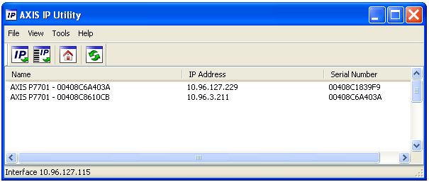
Legal Considerations                                         Equipment Modifications
Video and audio surveillance can be prohibited by laws       This equipment must be installed and used in strict
that vary from country to country. Check the laws in         accordance with the instructions given in the user
your local region before using this product for              documentation. This equipment contains no
surveillance purposes.                                       user-serviceable components. Unauthorized equipment
This product includes one (1) H.264, (1) MPEG-4 part 2,      changes or modifications will invalidate all applicable
and (1) AAC decoder license. To purchase further             regulatory certifications and approvals.
licenses, contact your reseller.
                                                             Liability
Electromagnetic Compatibility (EMC)                          Every care has been taken in the preparation of this
This equipment generates, uses and can radiate radio         document. Please inform your local Axis office of any
frequency energy and, if not installed and used in           inaccuracies or omissions. Axis Communications AB
accordance with the instructions, may cause harmful          cannot be held responsible for any technical or
interference to radio communications. However, there is      typographical errors and reserves the right to make
no guarantee that interference will not occur in a           changes to the product and documentation without
particular installation.                                     prior notice. Axis Communications AB makes no
                                                             warranty of any kind with regard to the material
If this equipment does cause harmful interference to         contained within this document, including, but not
radio or television reception, which can be determined       limited to, the implied warranties of merchantability
by turning the equipment off and on, the user is             and fitness for a particular purpose. Axis
encouraged to try to correct the interference by one or      Communications AB shall not be liable nor responsible
more of the following measures: Re-orient or relocate        for incidental or consequential damages in connection
the receiving antenna. Increase the separation between       with the furnishing, performance or use of this material.
the equipment and receiver. Connect the equipment to
an outlet on a different circuit to the receiver. Consult    RoHS
your dealer or an experienced radio/TV technician for        This product complies with both the European
help. Shielded (STP) network cables must be used with        RoHS directive, 2002/95/EC, and the Chinese
this unit to ensure compliance with EMC standards.           RoHS regulations, ACPEIP.
USA - This equipment has been tested and found to            WEEE Directive
comply with the limits for a Class B computing device
pursuant to Subpart B of Part 15 of FCC rules, which are     The European Union has enacted a Directive
designed to provide reasonable protection against such       2002/96/EC on Waste Electrical and Electronic
interference when operated in a commercial                   Equipment (WEEE Directive). This directive is
environment. Operation of this equipment in a                applicable in the European Union member
residential area is likely to cause interference, in which   states.
case the user at his/her own expense will be required to     The WEEE marking on this product (see right) or its
take whatever measures may be required to correct the        documentation indicates that the product must not be
interference.                                                disposed of together with household waste. To prevent
                                                             possible harm to human health and/or the environment,
Canada - This Class B digital apparatus complies with        the product must be disposed of in an approved and
Canadian ICES-003.                                           environmentally safe recycling process. For further
                                                             information on how to dispose of this product correctly,
Europe -       This digital equipment fulfills the           contact the product supplier, or the local authority
requirements for radiated emission according to limit B      responsible for waste disposal in your area.
of EN55022, and the requirements for immunity                Business users should contact the product supplier for
according to EN55024 residential and commercial              information on how to dispose of this product correctly.
industry.                                                    This product should not be mixed with other commercial
Japan - This is a class B product based on the standard      waste. For more information, visit
of the Voluntary Control Council for Interference from       www.axis.com/techsup/commercial waste.
Information Technology Equipment (VCCI). If this is used
near a radio or television receiver in a domestic            Support
environment, it may cause radio interference. Install and    Should you require any technical assistance, please
use the equipment according to the instruction manual.       contact your Axis reseller. If your questions cannot be
                                                             answered immediately, your reseller will forward your
Australia - This electronic device meets the                 queries through the appropriate channels to ensure a
requirements of the Radio communications                     rapid response. If you are connected to the Internet, you
(Electromagnetic Compatibility) Standard AS/NZS              can:
CISPR22.                                                     • download user documentation and firmware updates
                                                             • find answers to resolved problems in the FAQ database.
Safety                                                         Search by product, category, or phrases
Complies to EN 60950-1 (IEC 60950-1), Safety of              • report problems to Axis support by logging in to your
Information Technology Equipment.                              private support area.

                                                             The AXIS P7701 uses a 3.0V CR2032 Lithium battery,
                                                             for more information please see page 71.
AXIS P7701 Installation Guide Page 3
AXIS P7701 Installation Guide
This installation guide provides instructions for installing the AXIS P7701 Video Decoder on your
network. For all other aspects of using the product, please see the User’s Manual, available on the
CD included in this package, or from www.axis.com/techsup
Installation steps
1. Check the package contents against the list below.
ENGLISH
2. Hardware overview. See page 4.
3. Install the hardware. See page 8.
4. Assign an IP address. See page 9.
5. Set the password. See page 12. Important!
This product must be used in
compliance with local laws and
regulations.
Package contents
Item Models/variants/notes
Video decoder AXIS P7701 - Video Decoder
PS-T or PS-K indoor power Europe
supply UK
(country specific) Australia
USA/Japan
Argentina
Korea
Terminal block connector 4-pin connector block for connecting external devices to the I/O terminal
connector
DC power in terminal connector
RS422/485 terminal connectors
Mounting kit Two tamper-proof screws
One sheet of 4 rubber feet
Two wall plugs
CD AXIS Network Video Product CD, including product documentation,
installation tools and other software
Printed Materials AXIS P7701 Installation Guide (this document)
Axis Warranty DocumentPage 4 AXIS P7701 Installation Guide
Hardware overview
Top view
Mounting holes
Rear view
DVI-I connector Network connector (PoE)
OUT
DVI OUT PoE
P OWE R
P WR S TAT NE T V IDE O
- +
LED indicators for
power, status, Power adapter connector
network and video
Audio, Video and I/O side view Control button side view
RS-422/RS-485 connector
RS-485/422 I/O
AUDIO OUT
VIDEO OUT
RX/TX TX 1 2 3 4
Control button
Audio out 4-pin I/O terminal Video out
Dimensions
HxWxD = 33 x 99 x 118mm (1.3" x 3.9" x 4.7")
Weight = 318g (0.7 lb) power supply excl.AXIS P7701 Installation Guide Page 5
Unit connectors
Network connector - RJ-45 Ethernet connector. Supports Power over Ethernet (PoE). Using
shielded cables is recommended.
Power connector - 2-pin terminal block used for power input to the video decoder
with the supplied power adapter or an external power supply 8-20V DC, max. 8.3 W.
Function Pin number Description 1 2
ENGLISH
GND 1 Ground
DC Power 2 Power input 8-20V DC, max 8.3W
Note:
Do not connect a power supply if the video decoder is connected to PoE.
Audio out - Audio output that can be connected to a public address (PA) system or an active
speaker with a built-in amplifier. A pair of headphones can also be attached. A stereo connector
must be used for the audio out.
DVI-I connector - The DVI-I connector has both analog and digital signals present simultaneously,
so the DVI connector can be used to connect to a monitor with either digital or analog input.
For digital input, the DVI-I connector can also be used to connect the AXIS P7701 to a monitor with
a DVI input, or to a monitor with a HDMI connector with the addition of a DVI-to-HDMI adapter.
The DVI connector can also be used with a DVI-to-VGA adapter to connect the AXIS P7701 to a
monitor with a VGA analog input.
RCA connector - Standard phono-type connector for composite video in PAL or NTSC. Allows
direct connection of an analog TV device.
Note:
If you connect the AXIS P7701 to a monitor using the RCA connector, you cannot use the DVI-I con-
nector at the same time to connect to a second monitor.
I/O terminal connector - The AXIS P7701 has one digital input that is used
for a video select switch, and it has an interface for auxiliary power and
GND. The fourth I/O pin is unused.
Notes:
• The AXIS P7701 can deliver a maximum output of 1.6W on the I/O terminal 1 2 3 4
connector.Page 6 AXIS P7701 Installation Guide
• The video switch is not part of the AXIS P7701, and there is currently no optional video switch available
from Axis. However, it is possible for you to easily connect your own switch. See the connection diagram
below.
Function Pin Notes Specifications
GND 1 Ground
3.3V DC 2 Can be used to power auxiliary equipment. Max. load = 50mA
Power Note: This pin can only be used as power out.
Digital 3 Input for a video select switch.
Input
Unused 4 Unused
The following connection diagram gives an example of how to connect an auxiliary device to the
AXIS P7701.
AXIS P7701 1
Switch
Push to trigger video select
3.3V max 50mA 2
3 video input
4 UnusedAXIS P7701 Installation Guide Page 7
RS-422/RS-485 connector - Two 2-pin terminal blocks for RS-485/422 serial interface used to
control auxiliary equipment, e.g. PTZ devices.
The RS-485/422 serial port can be configured to support: RS-485/422
• Two-wire RS-485 half duplex
• Four-wire RS-485 full duplex
• Two-wire RS422 simplex
• Four-wire RS422 full duplex point to point communication RX/TX TX
1 2 3 4
ENGLISH
Function Pin Notes
RS-485/422 RX/TX A 1 (RX) For full duplex RS-485/422
(RX/TX) For half duplex RS-485
RS-485/422 RX/TX B 2
RS-485/422 TX A 3 (TX) For all modes
RS-485/422 TX B 4
LED indicators
LED Color Indication
Video Green Encoder/Camera is connected.
Amber Steady when connecting to an Encoder/Camera.
Red No Encoder/Camera is connected.
Network Green Steady for connection to a 100 Mbit/s network. Flashes for network activity.
Amber Steady for connection to 10 Mbit/s network. Flashes for network activity.
Unlit No network connection.
Status Green Steady green for normal operation.
Amber Steady during startup, during reset to factory default or when restoring settings.
Red Slow flash for failed upgrade.
Power Green Normal operation.
Amber Flashes green/amber during firmware upgrade.Page 8 AXIS P7701 Installation Guide
Install the hardware
! IMPORTANT! - The casing of the AXIS P7701 is not approved for outdoor use - the
product may only be installed in indoor environments.
Mount the video decoder
The video decoder is supplied with a mounting kit containing screws, plugs, and protective pads for
mounting the video decoder to a concrete wall:
1. Place the video decoder against the wall, and mark the location of the two mounting holes
(See Hardware overview, on page 4) through which the video decoder will be attached.
2. Remove the video decoder and drill the two mounting holes.
3. Punch out the four protective pads and apply them to the underside of the video decoder.
4. Insert the wall plugs into the wall, position the video decoder, and attach it to the wall using
the screws provided.
Connect the cables
1. Connect the decoder to the network using a shielded network cable.
2. Optionally connect external input/output devices, e.g. alarm devices. See Unit connectors, on
page 5 for information on the terminal connector pins.
3. Optionally connect an active speaker and/or external microphone.
4. Connect the decoder to the monitor.
5. Connect power, using one of the methods listed below:
• PoE (Power over Ethernet, Class 2). If available, this is automatically detected when the
network cable is connected (see above).
• Connect the supplied indoor power supply to the power connector on the decoder.
6. Check that the indicator LEDs indicate the correct conditions. See the table in LED indicators, on
page 7 for further details.AXIS P7701 Installation Guide Page 9
Assign an IP address
Follow these instructions to assign an IP address or see page 13 for other methods of connecting the
AXIS P7701 to the Internet.
Assign an IP address
Most networks today have a DHCP server that automatically assigns IP addresses to connected
devices. If your network does not have a DHCP server the AXIS P7701 will use 192.168.0.90 as the
default IP address.
ENGLISH
If you would like to assign a static IP address, the recommended method in Windows is either AXIS
IP Utility or AXIS Camera Management. Depending on the number of decoders you wish to install,
use the method that best suits your purpose.
Both of these free applications are available on the Axis Network Video Product CD supplied with
this product, or they can be downloaded from www.axis.com/techsup
Method Recommended for Operating system
AXIS IP Utility Single camera Windows
See page 10 Small installations
AXIS Camera Management Multiple cameras Windows 2000
See page 11 Large installations Windows XP Pro
Installation on a different subnet Windows 2003 Server
Windows Vista
Notes:
• If assigning the IP address fails, check that there is no firewall blocking the operation.
• For other methods of assigning or discovering the IP address of the AXIS P7701, e.g. in other operating
systems, see page 13.Page 10 AXIS P7701 Installation Guide AXIS IP Utility - single decoder/small installation AXIS IP Utility automatically discovers and displays Axis devices on your network. The application can also be used to manually assign a static IP address. Note that the computer running AXIS IP Utility must be on the same network segment (physical subnet) as the AXIS P7701. Automatic discovery 1. Check that the AXIS P7701 is connected to the network and that power has been applied. 2. Start AXIS IP Utility. 3. When the decoder appears in the window, double-click it to open its home page. 4. See page 12 for instructions on how to assign the password. Assign the IP address manually (optional) 1. Acquire an unused IP address on the same network segment as your computer. 2. Select the AXIS P7701 in the list. 3. Click the button Assign new IP address to the selected device and enter the IP address. 4. Click the Assign button and follow the on-screen instructions. Note that the decoder must be restarted within 2 minutes for the new IP address to be set. 5. Click the Home Page button to access the decoder’s web pages. 6. See page 12 for instructions on how to set the password.
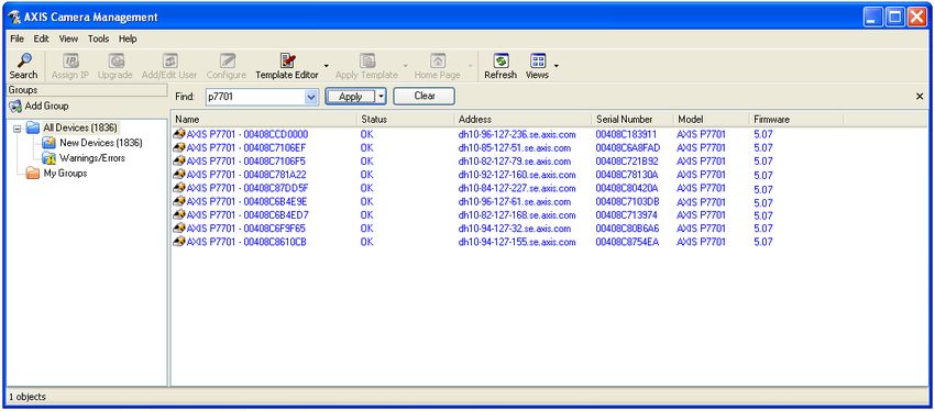
AXIS P7701 Installation Guide                                                       Page 11

AXIS Camera Management - multiple decoders/large installations
AXIS Camera Management can automatically discover multiple Axis devices, show connection
status, manage firmware upgrades and set IP addresses.

                                                                                              ENGLISH
Automatic discovery
1. Check that the decoder is connected to the network and that power has been applied.
2. Start AXIS Camera Management. When the AXIS P7701 appears in the window, double-click it
   to open the decoder’s home page.
3. See page 12 for instructions on how to set the password.

Assign an IP address in a single device
1. Select AXIS P7701 in AXIS Camera Management and click the
    Assign IP button.
2. Select Assign the following IP address and enter the IP
   address, subnet mask and default router the device will use.
3. Click the OK button.

Assign IP addresses in multiple devices
AXIS Camera Management speeds up the process of assigning IP
addresses to multiple devices, by suggesting IP addresses from a
specified range.
1. Select the devices you wish to configure (different models can
   be selected) and click the Assign IP button.
2. Select Assign the following IP address range and enter the
   range of IP addresses, the subnet mask and default router the
   devices will use.
3. Click the OK button.
Page 12 AXIS P7701 Installation Guide
Set the password
To gain access to the product, the password for the default administrator user root must be set. This
is done in the ‘Configure Root Password’ dialog, which is displayed when the AXIS P7701 is
accessed for the first time.
To prevent network eavesdropping when setting the root password, this can be done via an
encrypted HTTPS connection, which requires an HTTPS certificate (see note below).
To set the password via a standard HTTP connection, enter it directly in the first dialog shown
below.
To set the password via an encrypted HTTPS connection, follow these steps:
1. Click the Create self-signed certificate button.
2. Provide the requested information and click OK. The certificate is created and the password can
now be set securely. All traffic to and from the AXIS P7701 is encrypted from this point on.
3. Enter a password and then re-enter it to confirm the spelling. Click OK. The password has now
been configured.
To create an HTTPS connection,
start by clicking this button.
To configure the password directly
via an unencrypted connection, enter
the password here.
4. To log in, enter the user name “root” in the dialog as requested
Note: The default administrator user name root cannot be deleted.
5. Enter the password as set above, and click OK.AXIS P7701 Installation Guide Page 13
Other methods of setting the IP address
The table below shows the other methods available for setting or discovering the IP address. All
methods are enabled by default, and all can be disabled.
Use in operating Notes
system
AVHS Service All To connect the decoder to an AVHS server, refer to the server
Connection provider’s Installation guide. For information and help to find a
local AVHS Service Provider go to www.axis.com
ENGLISH
AXIS Dynamic DNS All A free service from Axis that allows you to quickly and simply
Service install your decoder. Requires an Internet connection with no
HTTP proxy. See www.axiscam.net for more information.
ARP/Ping All See below. The command must be issued within 2 minutes of
connecting power to the decoder.
UPnP™ Windows When enabled on your computer, the decoder is automatically
(ME or XP) detected and added to “My Network Places.”
Bonjour MAC OSX Applicable to browsers with support for Bonjour. Navigate to the
(10.4 or later) Bonjour bookmark in your browser (e.g. Safari) and click on the
link to access the decoder’s web pages.
View DHCP server All To view the admin pages for the network DHCP server, see the
admin pages server’s own documentation.
Set the IP address with ARP/Ping
1. Acquire an IP address on the same network segment your computer is connected to.
2. Locate the serial number (S/N) on the AXIS P7701 label.
3. Open a command prompt on your computer and enter the following commands:
Windows syntax: Windows example:
arp -s arp -s 192.168.0.125 00-40-8c-18-10-00
ping -l 408 -t ping -l 408 -t 192.168.0.125
UNIX/Linux/Mac syntax: UNIX/Linux/Mac example:
arp -s temp arp -s 192.168.0.125 00:40:8c:18:10:00 temp
ping -s 408 ping -s 408 192.168.0.125
4. Check that the network cable is connected to the decoder and then start/restart the decoder, by
disconnecting and reconnecting power.
5. Close the command prompt when you see ‘Reply from 192.168.0.125: ...’ or similar.
6. In your browser, type in http:// in the Location/Address field and press Enter on
your keyboard.
Notes:
• To open a command prompt in Windows: from the Start menu, select Run... and type cmd. Click OK.
• To use the ARP command on a Mac OS X, use the Terminal utility in Application > Utilities.Page 14 AXIS P7701 Installation Guide
Resetting to the Factory Default Settings
This will reset all parameters, including the IP address, to the Factory Default settings:
1. Disconnect power from the decoder.
2. Press and hold the Control button and reconnect power.
3. Keep the Control button pressed until the Power indicator displays amber (this may take up to
15 seconds).
4. Release the Control button. When the Power indicator displays green (which can take up to 1
minute) the process is complete and the decoder has been reset.
5. Re-assign the IP address, using one of the methods described in this document.
It is also possible to reset parameters to the original factory default settings via the web interface.
For more information, please see the online help or the user’s manual.
Accessing the decoder from the Internet
Once installed, your AXIS P7701 is accessible on your local network (LAN). To access the decoder
from the Internet, network routers must be configured to allow incoming traffic, which is usually
done on a specific port
• HTTP port (default port 80) for configuration
Please refer to the documentation for your router for further instructions. For more information on
this and other topics, visit the Axis Support Web at www.axis.com/techsup
Further information
The user’s manual is available from the Axis Web site at www.axis.com or from the Axis Network
Video Product CD supplied with this product.
Tip!
Visit www.axis.com/techsup to check if there is updated firmware available for your AXIS
P7701. To see the currently installed firmware version, see About.Guide d’installation de l’AXIS P7701 Page 15
AXIS P7701 Guide d’installation
Ce guide d’installation explique comment installer le Décodeur vidéo AXIS P7701 sur votre réseau.
Pour toute autre question concernant l’utilisation du produit, reportez-vous au Manuel de
l’utilisateur que vous trouverez sur le CD joint ou sur le site www.axis.com/techsup
Procédure d’installation
1. Vérification du contenu de l’emballage par rapport à la liste ci-dessous.
2. Vue d’ensemble du matériel. Reportez-vous à la page 16.
3. Installation du matériel. Reportez-vous à la page 20.
4. Attribution d’une adresse IP. Reportez-vous à la page
21. Important !
Ce produit doit être utilisé
FRANÇAIS
5. Configuration du mot de passe. Reportez-vous à la page
25. conformément aux lois et
dispositions locales en vigueur.
Contenu de l’emballage
Article Modèles/variantes/remarques
Décodeur vidéo AXIS P7701 - Décodeur vidéo
Alimentation d’intérieur PS-T Europe
ou PS-K Royaume-Uni
(selon le pays) Australie
États-Unis/Japon
Argentine
Corée
Bloc de connexion pour Bloc de connexion à 4 broches pour le raccordement d’équipements externes
terminaux au connecteur pour terminaux
Alimentation en courant continu du connecteur pour terminaux
Connecteurs pour terminaux RS422/485
Kit de montage Deux vis inviolables
Un jeu de 4 patins en caoutchouc
Deux chevilles
CD CD de la caméra vidéo sur IP Axis comprenant la documentation,
les outils d’installation et les autres logiciels
Documentation imprimée Guide d’installation de l’AXIS P7701 (le présent document)
Document de garantie d’AxisPage 16 AXIS P7701 Guide d’installation
Description du matériel
Vue de dessus
Trous de fixation
Vue de derrière
Connecteur DVI-I Connecteur réseau (PoE)
OUT
DVI OUT PoE
P OWE R
P WR S TAT NE T V IDE O
- +
Voyants pour
l’alimentation, l’état, Connecteur d’adaptateur secteur
le réseau et la vidéo
Vue de côté E/S, audio et vidéo Vue de côté bouton de commande
Connecteur RS-422/RS-485
RS-485/422 I/O
AUDIO OUT
VIDEO OUT
RX/TX TX 1 2 3 4
Bouton de
Sortie Terminal d’E/S à 4 Sortie commande
audio broches vidéo
Dimensions
H x L x P = 33 x 99 x 118 mm
Poids = 318 g (alimentation exclue)Guide d’installation de l’AXIS P7701 Page 17
Connecteurs de l’appareil
Connecteur réseau - Connecteur Ethernet RJ-45. Prend en charge l’alimentation par Ethernet
(PoE). Il est recommandé d’utiliser des câbles blindés.
Connecteur d’alimentation - Bloc terminal à 2 broches utilisé pour alimenter le
décodeur vidéo avec l’adaptateur secteur fourni ou un bloc d’alimentation externe 8-
20 V CC, max. 8,3 W.
1 2
Fonction Numéro de broche Description
Terre 1 Terre
Alimentation CC 2 Puissance d’entrée 8-20 V CC, max. 8,3 W
FRANÇAIS
Remarque :
Ne branchez pas l’alimentation électrique si le décodeur vidéo est branché sur PoE.
Sortie audio - Sortie audio pouvant être connectée à un système de diffusion publique ou à un
haut-parleur actif avec amplificateur intégré. Il est également possible de connecter une paire
d’écouteurs. Un connecteur stéréo doit être utilisé pour la sortie audio.
Connecteur DVI-I - Le connecteur DVI-I prend en charge les signaux analogiques et numériques. Le
connecteur DVI peut ainsi être utilisé pour brancher un écran à une entrée analogique ou
numérique.
Pour une entrée numérique, le connecteur DVI-I peut aussi être utilisé pour brancher l’AXIS P7701 à
un écran équipé d’un connecteur HDMI au moyen d’un adaptateur DVI-HDMI.
Le connecteur DVI peut être utilisé avec un adaptateur DVI-VGA pour brancher l’AXIS P7701 à un
écran avec entrée VGA analogique.
Connecteur RCA - Connecteur standard de type phono pour des vidéos composites PAL ou NTSC.
Permet la connexion directe à un périphérique TV analogique.
Remarque :
Si vous branchez l’AXIS P7701 à un écran au moyen d’un connecteur RCA, il est impossible de se servir
du connecteur DVI-I en même temps pour brancher un deuxième écran.
Connecteur pour terminaux E/S - L’AXIS P7701 possède une entrée
numérique pour un bouton de sélection vidéo. Il est doté d’une interface
pour l’alimentation auxiliaire et la terre. La quatrième broche E/S est
inutilisée.
1 2 3 4Page 18 AXIS P7701 Guide d’installation
Remarques :
• L´Axis P7701 peut fournir une sortie maximum de 1.6W sur le connecteur pour terminaux E/S.
• L´interrupteur video n´est pas fourni avec l´Axis P7701, et il n´y a actuellement pas d´interrupteur vidéo
optionnel disponible chez Axis. Cependant, il vous est possible facilement de connecter votre propore
interrupteur en suivant le schéma de connection ci-dessous.
Fonction Broche Remarques Caractéristiques techniques
Terre 1 Terre
Alimentation 2 Cette broche peut également servir à Charge maximale = 50 mA
en courant l’alimentation du matériel auxiliaire.
continu de Remarque : la broche peut être utilisée
3,3 V uniquement comme sortie d’alimentation.
Entrée 3 Entrée pour bouton de sélection de vidéo.
numérique
Inutilisée 4 Inutilisée
Le schéma de câblage suivant est un exemple de connexion d’un périphérique auxiliaire à l’AXIS
P7701.
AXIS P7701 1
Interrupteur pour déclencher
la sélection de la vidéo
3.3V max 50mA 2
3 entrée-vidéo
4 inutiliséGuide d’installation de l’AXIS P7701 Page 19
Connecteur RS-422/RS-485 - Deux blocs terminaux à 2 broches pour l’interface série RS-485/422
utilisée pour le contrôle des équipements auxiliaires (appareils PTZ, etc.).
Le port série RS-485/422 peut être configuré pour la prise en charge de : RS-485/422
• RS-485 semi-duplex sur deux fils
• RS-485 semi-duplex sur quatre fils
• RS422 simplex sur deux fils
• RS422 duplex intégral sur quatre fils pour communication point à RX/TX TX
point 1 2 3 4
Fonction Broche Remarques
RS-485/422 RX/TX A 1 (RX) Pour RS-485/422 duplex intégral
(RX/TX) Pour RS-485 semi-duplex
RS-485/422 RX/TX B 2
FRANÇAIS
RS-485/422 TX A 3 (TX) Pour tous modes
RS-485/422 TX B 4
Témoins lumineux
DEL Couleur Indication
Vidéo Vert Encodeur/Caméra connecté.
Orange Continu lors de la connexion à un Encodeur/Caméra.
Rouge Aucun Encodeur/Caméra n’est connecté.
Net (Réseau) Vert Continu en cas de connexion à un réseau de 100 Mbits/s. Clignote en cas
d’activité réseau.
Orange Continu en cas de connexion à un réseau de 10 Mbits/s. Clignote en cas
d’activité réseau.
Éteint Pas de connexion au réseau.
Status (État) Vert Vert continu en cas de fonctionnement normal.
Orange En continu pendant le démarrage, la réinitialisation des paramètres d’usine par
défaut ou la restauration des paramètres.
Rouge Clignote lentement en cas d’échec de la mise à niveau.
PWR Vert Fonctionnement normal.
(Alimentation)
Orange Clignote en vert/orange pendant la mise à niveau du microprogramme.Page 20 AXIS P7701 Guide d’installation
Installation du matériel
! IMPORTANT ! Le boîtier de l’AXIS P7701 n’est pas approuvé pour une utilisation à
l’extérieur. Le produit doit être installé en intérieur uniquement.
Montage du décodeur vidéo
Le décodeur vidéo est fourni avec un kit de montage contenant des vis, des chevilles et des patins
de protection pour la fixation du décodeur vidéo sur un mur en béton :
1. placez le décodeur vidéo contre le mur et marquez l’emplacement des deux trous
(Reportez-vous à la section Description du matériel, page 16) où le décodeur vidéo sera fixé.
2. retirez le décodeur vidéo et percez les deux trous.
3. sortez les quatre patins de protection de leur emballage et posez sur le dessous du décodeur
vidéo.
4. insérez les chevilles dans le mur, positionnez le décodeur vidéo et fixez-le au mur à l’aide
des vis fournies.
Branchement des câbles
1. Connectez le décodeur au réseau à l’aide d’un câble réseau blindé.
2. Si vous le souhaitez, connectez des dispositifs d’entrée/sortie externes, tels que des systèmes
d’alarme. Reportez-vous à la section Connecteurs de l’appareil, page 17 pour plus
d’informations sur les broches du connecteur pour terminaux.
3. Si vous le souhaitez, vous pouvez brancher un haut-parleur actif et/ou un microphone externe.
4. Connectez le décodeur à l’écran.
5. Branchez l’alimentation en suivant une des méthodes décrites ci-dessous :
• PoE (alimentation par Ethernet, classe 2). le PoE, si il est disponible, est
• automatiquement détecté lorsque le câble réseau est connecté (voir ci-dessus).
• branchez le bloc d’alimentation d’intérieur fourni sur le connecteur d’alimentation du
décodeur.
6. vérifiez que les voyants lumineux indiquent les conditions correctes. Pour plus d’informations,
reportez-vous au tableau de la section Témoins lumineux, page 19.Guide d’installation de l’AXIS P7701 Page 21
Attribution d’une adresse IP
Procédez comme suit pour définir une adresse IP ou Reportez-vous à la page 26 pour d’autres
méthodes de connexion du AXIS P7701 à Internet.
Attribution d’une adresse IP
Aujourd’hui, la plupart des réseaux sont équipés d’un serveur DHCP qui attribue automatiquement
des adresses IP aux périphériques connectés. Si votre réseau en est dépourvu, votre AXIS P7701
utilisera 192.168.0.90 comme adresse IP par défaut.
Si vous souhaitez paramétrer une adresse IP statique sous Windows, nous recommandons
l’utilisation de l’application AXIS IP Utility ou de l’application AXIS Camera Management. Selon le
nombre de décodeurs à installer, utilisez la méthode qui vous convient le mieux.
Ces deux applications gratuites sont disponibles sur le CD de la caméra vidéo sur IP Axis fourni avec
FRANÇAIS
ce produit. Vous pouvez également les télécharger à partir du site www.axis.com/techsup.
Méthode Recommandée pour Système
d’exploitation
AXIS IP Utility Une seule caméra Windows
Reportez-vous à la page 22 Petites installations
AXIS Camera Management Plusieurs caméras Windows 2000
Reportez-vous à la page Grandes installations Windows XP Pro
23 Installation sur un autre sous- Windows 2003 Server
réseau Windows Vista
Remarques :
• En cas d’échec de l’attribution d’adresse IP, vérifiez qu’aucun pare-feu ne bloque l’opération.
• Pour connaître les autres méthodes d’affectation ou de détection de l’adresse IP de votre AXIS P7701, par
exemple sous d’autres systèmes d’exploitation, reportez-vous à la page 26.Page 22 AXIS P7701 Guide d’installation AXIS IP Utility - Un seul décodeur/petite installation AXIS IP Utility détecte automatiquement les périphériques Axis de votre réseau et les affiche. Cette application sert également à attribuer manuellement une adresse IP statique. Notez que l’ordinateur exécutant l’application AXIS IP Utility doit se trouver sur le même segment de réseau (sous-réseau physique) que l’AXIS P7701. Recherche automatique 1. Vérifiez que l’AXIS P7701 est connecté au réseau et qu’il est sous tension. 2. Lancez AXIS IP Utility. 3. Double-cliquez sur l’icône du décodeur, lorsque celle-ci apparaît dans la fenêtre, pour ouvrir la page d’accueil correspondante. 4. Reportez-vous à la page 25 pour savoir comment configurer le mot de passe. Attribution manuelle de l’adresse IP (facultatif) 1. Trouvez une adresse IP inutilisée sur le même segment de réseau que celui de votre ordinateur. 2. SélectionnezAXIS P7701 dans la liste. 3. Cliquez sur le bouton Assign new IP address to the selected device (Attribuer une nouvelle adresse IP au périphérique sélectionné) et saisissez l’adresse IP. 4. Cliquez sur le bouton Assign (Attribuer) et suivez les instructions affichées à l’écran. Le décodeur doit être redémarré dans les 2 minutes pour que la nouvelle adresse IP soit prise en compte. 5. Cliquez sur le bouton Home Page (Page d’accueil) pour accéder aux pages Web du décodeur. 6. Reportez-vous à la page 25 pour la configuration du mot de passe.
Guide d’installation de l’AXIS P7701                                                    Page 23

AXIS Camera Management : plusieurs décodeurs et de grandes
installations
AXIS Camera Management peut détecter automatiquement plusieurs périphériques Axis, afficher
l’état de connexion, gérer les mises à niveau du microprogramme et configurer les adresses IP.

                                                                                                  FRANÇAIS
Recherche automatique
1. Vérifiez que le décodeur est connecté au réseau et qu’il est sous tension.
2. Lancez AXIS Camera Management. Double-cliquez sur l’icône de l’AXIS P7701 lorsqu’elle
   apparaît dans la fenêtre pour ouvrir la page d’accueil du décodeur.
3. Reportez-vous à la page 25 pour la configuration du mot de passe.

Attribution d’une adresse IP à un seul périphérique
1. SélectionnezAXIS P7701 dans l’application AXIS Camera
   Management, puis cliquez sur le bouton Assign IP (Attribuer
    une adresse IP).
2. Sélectionnez Assign the following IP address (Attribuer
   l’adresse IP suivante) et saisissez l’adresse IP, le masque de
   sous-réseau et le routeur par défaut que le périphérique
   utilisera.
3. Cliquez sur le bouton OK.

Attribution d’adresses IP à plusieurs périphériques
AXIS Camera Management accélère le processus d’attribution
d’adresses IP à plusieurs périphériques en suggérant des adresses IP
parmi une plage spécifiée.
1. Sélectionnez les périphériques à configurer (il peut s’agir de
   plusieurs modèles), puis cliquez sur le bouton Assign IP
    (Attribuer une adresse IP).
Page 24 AXIS P7701 Guide d’installation 2. Sélectionnez Assign the following IP address range (Attribuer la plage d’adresses IP suivante) et saisissez la plage d’adresses IP, le masque de sous-réseau et le routeur par défaut que les périphériques utiliseront. 3. Cliquez sur le bouton OK.
Guide d’installation de l’AXIS P7701                                                          Page 25

    Configuration du mot de passe
Pour accéder au produit, le mot de passe par défaut de l’administrateur, root, doit être configuré.
Vous pouvez effectuer cette opération dans la boîte de dialogue Configure Root Password
(Configurer le mot de passe root) qui s’affiche lors du premier accès à l’AXIS P7701.
Pour éviter les écoutes électroniques lors de la configuration du mot de passe root, utilisez une
connexion HTTPS cryptée nécessitant un certificat HTTPS (voir la remarque ci-dessous).
Pour configurer le mot passe avec une connexion HTTP standard, saisissez directement le mot de
passe dans la première boîte de dialogue représentée ci-dessous.
Pour configurer le mot passe avec une connexion HTTPS cryptée, procédez comme suit :
1. cliquez sur le bouton Create self-signed certificate (Créer un certificat autosigné).
2. saisissez les informations demandées, puis cliquez sur OK. le certificat est créé et le mot de

                                                                                                        FRANÇAIS
   passe peut maintenant être configuré en toute sécurité. tout le trafic vers et depuis l’AXIS
   P7701 est désormais crypté.
3. saisissez un mot de passe, puis saisissez-le de nouveau pour confirmation. cliquez sur OK. le
   mot de passe est maintenant configuré.

                                                      Pour créer une connexion HTTPS,
                                                      cliquez sur ce bouton.

   Pour configurer directement le mot
   de passe via une connexion cryptée,
   saisissez le mot de passe à cet
   endroit.

4. Pour vous connecter, saisissez le nom d’utilisateur « root » dans la boîte de dialogue à l’invite.
   Remarque : le nom d’utilisateur par défaut de l’administrateur est root et il ne peut pas être
   supprimé.
5. Saisissez le mot de passe configuré ci-dessus et cliquez sur OK.
Page 26 AXIS P7701 Guide d’installation
Autres méthodes de définition de l’adresse IP
Le tableau ci-dessous indique les autres méthodes permettant de configurer ou de déterminer
l’adresse IP. Toutes les méthodes sont activées par défaut et peuvent être désactivées.
Utilisation sous un Remarques
système
d’exploitation
AVHS Service Tous Pour connecter le décodeur à un serveur AVHS, reportez-vous au
Connection Guide d’installation du fournisseur. Pour obtenir des
renseignements et trouver un fournisseur de service VHS,
consultez le site www.axis.com
AXIS Dynamic DNS Tous Service gratuit offert par Axis pour vous permettre d’installer
Service rapidement et facilement votre décodeur. Nécessite une
connexion Internet sans proxy HTTP. Pour plus d’informations,
consultez le site www.axiscam.net.
ARP/Ping Tous Reportez-vous aux instructions ci-dessous. La commande doit
être saisie dans les 2 minutes suivant la mise sous tension du
décodeur.
UPnP™ Windows Lorsque le décodeur est activé sur votre ordinateur, il est détecté
(ME ou XP) et ajouté automatiquement au dossier Favoris réseau.
Bonjour MAC OS X Pour les navigateurs compatibles avec Bonjour : accédez au
(10.4 ou version signet Bonjour dans votre navigateur (par exemple, Safari), puis
ultérieure) cliquez sur le lien pour accéder aux pages Web du décodeur.
Affichage des pages Tous Pour consulter les pages administratives du serveur DHCP réseau,
administratives du reportez-vous à la documentation du serveur.
serveur DHCP
Définition de l’adresse IP à l’aide d’ARP/Ping
1. Trouvez une adresse IP sur le même segment de réseau que celui de votre ordinateur.
2. Repérez le numéro de série (S/N) sur l’étiquette de l’AXIS P7701.
3. Ouvrez une invite de commande sur votre ordinateur et saisissez les commandes suivantes :
Syntaxe pour Windows : Exemple pour Windows :
arp -s arp -s 192.168.0.125 00-40-8c-18-10-00
ping -l 408 -t ping -l 408 -t 192.168.0.125
Syntaxe pour UNIX/Linux/Mac : Exemple pour UNIX/Linux/Mac :
arp -s temp arp -s 192.168.0.125 00:40:8c:18:10:00 temp
ping -s 408 ping -s 408 192.168.0.125
4. Vérifiez que le câble réseau est connecté au décodeur, puis démarrez/redémarrez ce dernier en
débranchant, puis en rebranchant l’alimentation.
5. Fermez l’invite de commande lorsque le message « Reply from 192.168.0.125:... » (Réponse de
192.168.0.125 : ...) ...’ ou un message similaire s’affiche.Guide d’installation de l’AXIS P7701 Page 27
6. Dans votre navigateur, tapez http:// dans le champ Emplacement/Adresse, puis
appuyez sur la touche Entrée de votre clavier.
Remarques :
• Ouvrir une invite de commande sous Windows : dans le menu Démarrer, sélectionnez Exécuter… et tapez
cmd. Cliquez sur OK.
• Pour utiliser la commande ARP sous Mac OS X, utilisez l’utilitaire Terminal dans Application> Utilitaires.
FRANÇAISPage 28 AXIS P7701 Guide d’installation
Rétablissement des paramètres d’usine par défaut
Procédez comme suit pour rétablir tous les paramètres par défaut définis en usine, y compris
l’adresse IP :
1. débranchez l’alimentation du décodeur.
2. maintenez le bouton de commande enfoncé et rebranchez l’alimentation.
3. Appuyez sur le bouton jusqu’à ce que le voyant d’alimentation passe à l’orange et clignote (cela
peut prendre jusqu’à 15 secondes).
4. relâchez le bouton de commande. Quand le voyant d’alimentation émet une lumière verte (ce
qui peut prendre 1 minute), le décodeur est revenu aux réglages par défaut définis en usine.
5. Attribuez à nouveau l’adresse IP à l’aide de l’une des méthodes décrites dans ce document.
Il est également possible de rétablir les paramètres d’usine par défaut d’origine à partir de
l’interface web. Pour plus d’informations, reportez-vous à l’aide en ligne ou au manuel d’utilisation.
Accès au décodeur sur Internet
Une fois installée, votre AXIS P7701 est accessible sur votre réseau local (LAN). Pour accéder au
décodeur via Internet, des routeurs réseau doivent être configurés pour autoriser le trafic entrant,
ce qui est généralement réalisé sur un port spécifique.
• Port HTTP (port 80 par défaut) pour la configuration
Pour plus d’informations, consultez la documentation du routeur. Pour plus d’informations à ce
sujet ou pour toute autre question, consultez la page Axis Support Web à l’adresse www.axis.com/
techsup.
Plus d’informations
Le manuel de l’utilisateur est disponible sur le site Web d’Axis (www.axis.com) et sur le CD de la
caméra vidéo sur IP Axis fourni avec ce produit.
Conseil :
visitez le site www.axis.com/techsup pour vérifier si des mises à jour de microprogrammes
sont disponibles pour votre AXIS P7701. Pour connaître la version du microprogramme
actuellement installée, reportez-vous à la page About (Configuration - À propos de).AXIS P7701 Installationsanleitung Seite 29
AXIS P7701 Installationsanleitung
In dieser Anleitung wird die Installation der AXIS P7701 Video-Decoder in einem Netzwerk
beschrieben. Alle weiteren Hinweise zur Verwendung des Produkts finden Sie im Benutzerhandbuch,
das auf der mitgelieferten CD oder auf unserer Website unter www.axis.com zur Verfügung steht.
Installationsschritte
1. Prüfen Sie, ob alle in der nachfolgenden Liste aufgeführten Komponenten vorhanden sind.
2. Sehen Sie sich die Hardwareübersicht an. Siehe Seite 30.
3. Installieren Sie die Hardware. Siehe Seite 34.
4. Weisen Sie eine IP-Adresse zu. Siehe Seite 35.
5. Legen Sie das Kennwort fest. Siehe Seite 39. Wichtig!
Verwenden Sie dieses Produkt
unter Beachtung der geltenden
rechtlichen Bestimmungen.
Lieferumfang
DEUTSCH
Komponente Modell/Varianten/Anmerkungen
Video-Decoder AXIS P7701 - Video-Decoder
PS-T oder PS-K Netzteil für Europa
geschlossene Räume Großbritannien
(landesspezifisch) Australien
USA/Japan
Argentinien
Korea
Klemmenblock-Anschluss 4-polige E/A-Anschlussleiste
Gleichstromeingang
RS422/485-Anschlüsse
Montagesatz Zwei manipulationssichere Schrauben
Sortiment von 4 Gummifüßen
Zwei Wanddübel
CD CD für AXIS-Netzwerkvideoprodukte einschließlich Produktdokumentation,
Installationswerkzeugen und anderer Software
Gedruckte Dokumente AXIS P7701 Installationsanleitung (dieses Dokument)
Axis-GarantieerklärungSeite 30 AXIS P7701 Installationsanleitung
Hardwareübersicht
Draufsicht
Montagebohrungen
Rückansicht
DVI-I-Anschluss Netzwerkanschluss (mit PoE)
OUT
DVI OUT PoE
P OWE R
P WR S TAT NE T V IDE O
- +
LED-Anzeigen für
Strom, Status, Netzteilanschluss
Netzwerk und Video
Audio, Video und E/A (Seitenansicht) Steuertaste (Seitenansicht)
RS-422/RS-485-Anschluss
RS-485/422 I/O
AUDIO OUT
VIDEO OUT
RX/TX TX 1 2 3 4
Steuertaste
Audioaus 4-polige E/A- Video-
gang Anschlussklemme Ausgang
Abmessungen
H x B x T = 33 x 99 x 118mm
Gewicht = 318 g (ohne Netzteil)AXIS P7701 Installationsanleitung Seite 31
Geräteanschlüsse
Netzwerkanschluss - RJ-45-Ethernetanschluss. Unterstützt PoE-Anschluss (Power over Ethernet).
Die Verwendung von abgeschirmten Kabeln wird empfohlen.
Netzanschluss - 2-poliger Anschlussblock für Netzeingang. Zur Stromversorgung
des Video-Decoders über das mitgelieferte Netzteil oder ein externes Netzteil mit 8–
20 V Gleichstrom und max. 8,3 W.
1 2
Funktion Anschlussnummer Beschreibung
Schutzleiter 1 Masse
Gleichstrom 2 Netzeingang 8–20 V Gleichstrom, max. 8,3 W
Hinweis:
Schließen Sie kein Netzteil an, wenn der Video-Decoder über PoE angeschlossen ist.
Audioausgang - Audioausgang zum Anschließen einer Rundrufanlage (PA) oder eines
DEUTSCH
Aktivlautsprechers mit integriertem Verstärker. Auch ein Kopfhörer kann angeschlossen werden. Für
den Audioausgang muss ein Stereostecker benutzt werden.
DVI-I-Anschluss - Über den DVI-I-Anschluss ist die Übertragung analoger und digitaler Daten
möglich, so dass Sie Bildschirme mit digitalen und Analogeingängen anschließen können.
Als digitalen Eingang können Sie den AXIS P7701 über den DVI-I-Anschluss und einem geeigneten
DVI-zu-HDMI-Adapter auch an Bildschirme mit HDMI-Anschluss anschließen.
Mit Hilfe eines DVI-zu-VGA-Adapters ist außerdem der Anschluss des AXIS P7701 an Bildschirme
mit analogen VGA-Eingängen möglich.
RCA-Anschluss - Gebräuchlicher Cinch-Stecker für Composite Video in PAL oder NTSC. Ermöglicht
den direkten Anschluss von analogen TV-Geräten.
Hinweis:
Wenn Sie den AXIS P7701über den RCA-Anschluss an einen Bildschirm anschließen, ist es nicht
möglich, einen zweiten Bildschirm über den DVI-I-Anschluss anzuschließen.
E/A-Anschluss - Der AXIS P7701 verfügt über einen digitalen Eingang für
eine Videoauswahltaste und eine Schnittstelle für Zusatzstromversorgung
und Masse. Der vierte E/A-Kontakt ist nicht belegt.
Hinweise:
• Der AXIS P7701 kann eine maximale Leistung von 1,6 W auf der E/A Klemme 1 2 3 4
liefern.Seite 32 AXIS P7701 Installationsanleitung
• Der Video-Schalter ist im AXIS P7701 nicht integriert,und derzeit bietet Axis dieses Zubehör leider nicht an.
Es ist jedoch möglich, dass Sie Ihren eigenen Schalter anschliessen. Siehe Anschlussbild unten.
Funktion Kontakt Hinweise Spezifikationen
Schutzleiter 1 Masse
3,3 V 2 Dieser Kontakt kann auch für die Max. Stromstärke = 50 mA
Gleichstrom Stromversorgung von Zusatzgeräten verwendet
werden.
Hinweis: Dieser Anschluss kann nur als
Stromausgang verwendet werden.
Digitaler 3 Eingang für Videoauswahltaste.
Eingang
Nicht belegt 4 Nicht belegt
Das folgende Anschlussschaltbild zeigt ein Beispiel für den Anschluss eines Zusatzgeräts an den
AXIS P7701.
AXIS P7701 1
Switch
Push toz.B. Schalter
trigger video select
3.3V max 50mA 2
3 video input
4 UnusedAXIS P7701 Installationsanleitung Seite 33
RS-422/RS-485-Anschluss - Zwei 2-polige Anschlussblöcke für serielle Schnittstellen vom Typ
RS-485/422 zur Steuerung von Zusatzgeräten, wie z. B. PTZ-Geräten.
Der serielle RS-485/422-Anschluss kann in den folgenden Anschlussmodi RS-485/422
konfiguriert werden:
• zwei-Draht RS-485-Halbduplex-Anschluss
• vier-Draht RS-485-Vollduplex-Anschluss
• zwei-Draht RS422 Simplex-Anschluss RX/TX TX
• vier-Draht RS422-Vollduplex-Anschluss (Punkt-zu-Punkt- 1 2 3 4
Verbindung)
Funktion Kontakt Hinweise
RS-485/422 RX/TX A 1 (RX) Für Vollduplex RS-485/422
RS-485/422 RX/TX B 2 (RX/TX) Für Halbduplex RS-485
RS-485/422 TX A 3 (TX) Für alle Modi
RS-485/422 TX B 4
DEUTSCH
LED-Anzeigen
LED Farbe Bedeutung
Video Grün Encoder/Kamera ist angeschlossen.
Gelb Leuchtet dauerhaft bei Verbindung mit einem Encoder bzw. einer Kamera.
Rot Encoder/Kamera ist nicht angeschlossen.
Netzwerk Grün Leuchtet dauerhaft bei Verbindung mit einem 100-MBit/s-Netzwerk. Blinkt bei
Netzwerkaktivität.
Gelb Leuchtet dauerhaft bei Verbindung mit einem 10-MBit/s-Netzwerk. Blinkt bei
Netzwerkaktivität.
Leuchtet Keine Netzwerkverbindung vorhanden.
nicht
Status Grün Leuchtet bei Normalbetrieb konstant grün.
Gelb Leuchtet dauerhaft beim Start und beim Wiederherstellen der Werkseinstellungen
bzw. von vorherigen Einstellungen.
Rot Blinkt langsam bei Aktualisierungsfehler.
Betrieb Grün Normaler Betrieb.
Gelb Blinkt grün/gelb während Firmware-Aktualisierung.Seite 34 AXIS P7701 Installationsanleitung
Installation der Hardware
! WICHTIG! - Das Gehäuse des AXIS P7701 ist nicht für den Einsatz im Außenbereich
geeignet; das Gerät darf nur in Innenräumen installiert werden.
Montage des Video-Decoders
Der Video-Decoder wird mit einem Montagesatz mit Schrauben, Dübeln und Schutzfüßen geliefert,
um den Video-Decoder an einer Betonwand zu befestigen:
1. Halten Sie den Video-Decoder an die Wand und markieren Sie die Stelle der beiden
Montagebohrungen
(siehe Hardwareübersicht, auf Seite 30), über die der Video-Decoder befestigt wird.
2. Nehmen Sie den Video-Decoder ab und bohren Sie die Montagelöcher in die Wand.
3. Drücken Sie die vier Schutzfüße heraus und kleben Sie sie auf die Unterseite des Video-
Decoders.
4. Drücken Sie die Wanddübel in die Löcher, positionieren Sie den Video-Decoder an der Wand
und befestigen Sie ihn mit den
mitgelieferten Schrauben.
Anschließen der Kabel
1. Verbinden Sie den Decoder über ein abgeschirmtes Netzwerkkabel mit dem Netzwerk.
2. Sie können zusätzlich externe Geräte, wie z. B. Alarmanlagen, anschließen. Informationen zur
Anschlussbelegung finden Sie auf Geräteanschlüsse, auf Seite 31.
3. Sie können für eine bidirektionale Audioverbindung zusätzlich einen Aktivlautsprecher und/oder
ein externes Mikrofon anschließen.
4. Schließen Sie den Decoder an den Bildschirm an.
5. Schließen Sie die Kamera auf eine der folgenden Arten an die Stromversorgung an:
• PoE (Power over Ethernet, Klasse 2). Wenn PoE vorhanden ist, wird der Anschluss
automatisch bei Anschluss des Netzwerkkabels (siehe oben) erkannt.
• Schließen Sie das mitgelieferte Netzteil für Innenräume an den Netzanschluss des
Decoders an.
6. Überprüfen Sie, ob die LED-Anzeigen die Betriebszustände korrekt angeben. Weitere
Informationen hierzu finden Sie in der Tabelle unter LED-Anzeigen, auf Seite 33.AXIS P7701 Installationsanleitung Seite 35
Zuweisen einer IP-Adresse
Führen Sie die folgenden Schritte aus, um eine IP-Adresse zuzuweisen. Auf Seite 40 werden
alternative Methoden zur Verbindung des AXIS P7701 mit dem Internet beschrieben.
Zuweisen einer IP-Adresse
In den meisten Netzwerken ist heutzutage ein DHCP-Server eingebunden, der angeschlossenen
Geräten automatisch IP-Adressen zuweist. Wenn Ihr Netzwerk über keinen DHCP-Server verfügt,
wird für den AXIS P7701 die Standard-IP-Adresse 192.168.0.90 verwendet.
Zum Zuweisen einer statischen IP-Adresse stehen unter Windows die Programme AXIS IP Utility
und AXIS Camera Management zur Verfügung. Verwenden Sie die Methode, die für die gewünschte
Anzahl der zu installierenden Decoder geeignet ist.
Beide Anwendungen stehen kostenlos auf der mitgelieferten CD für Axis-Netzwerkvideoprodukte
zur Verfügung oder können unter „www.axis.com/techsup“ heruntergeladen werden.
Methode Empfohlen für Betriebssystem
AXIS IP Utility Einzelne Kamera Windows
Siehe Seite 36 Kleine Installationen
DEUTSCH
AXIS Camera Management Mehrere Kameras Windows 2000
Siehe Seite 37 Große Installationen Windows XP Pro
Installation in einem anderen Windows 2003 Server
Subnetz Windows Vista
Hinweise:
• Falls Sie die IP-Adresse nicht zuweisen können, müssen ggf. die Einstellungen der Firewall überprüft
werden.
• Weitere Informationen über alternative Methoden zum Festlegen bzw. Ermitteln der IP-Adresse des AXIS
P7701 (z. B. bei anderen Betriebssystemen) finden Sie auf Seite 40.Vous pouvez aussi lire