INSTALLATION GUIDE AXIS M31-VE Network Camera Series AXIS M3113-VE Network Camera AXIS M3114-VE Network Camera AXIS M3113-VE Nocap Network Camera ...
←
→
Transcription du contenu de la page
Si votre navigateur ne rend pas la page correctement, lisez s'il vous plaît le contenu de la page ci-dessous
INSTALLATION GUIDE

AXIS M31-VE Network Camera Series

                                         ENGLISH
    AXIS M3113-VE Network Camera

                                         FRANÇAIS
    AXIS M3114-VE Network Camera

    AXIS M3113-VE Nocap Network Camera

                                         DEUTSCH
    AXIS M3114-VE Nocap Network Camera

                                         ITALIANO
                                         ESPAÑOL
About this Document this equipment is intended to use mainly for home use
This document includes instructions for installing the and may be used in all areas.
AXIS M31-VE Network Cameras on your network. Equipment Modifications
Previous experience of networking will be beneficial
when installing the product. This equipment must be installed and used in strict
accordance with the instructions given in the user
Legal Considerations documentation. This equipment contains no
Video and audio surveillance can be prohibited by laws user-serviceable components. Unauthorized equipment
that vary from country to country. Check the laws in changes or modifications will invalidate all applicable
your local region before using this product for regulatory certifications and approvals.
surveillance purposes. Liability
This product includes one (1) H.264 decoder license. To
purchase further licenses, contact your reseller. Every care has been taken in the preparation of this
document. Please inform your local Axis office of any
Electromagnetic Compatibility (EMC) inaccuracies or omissions. Axis Communications AB
This equipment generates, uses and can radiate radio cannot be held responsible for any technical or
frequency energy and, if not installed and used in typographical errors and reserves the right to make
accordance with the instructions, may cause harmful changes to the product and documentation without
interference to radio communications. However, there is prior notice. Axis Communications AB makes no
no guarantee that interference will not occur in a warranty of any kind with regard to the material
particular installation. contained within this document, including, but not
limited to, the implied warranties of merchantability
If this equipment does cause harmful interference to and fitness for a particular purpose. Axis
radio or television reception, which can be determined Communications AB shall not be liable nor responsible
by turning the equipment off and on, the user is for incidental or consequential damages in connection
encouraged to try to correct the interference by one or with the furnishing, performance or use of this material.
more of the following measures: Re-orient or relocate RoHS
the receiving antenna. Increase the separation between
the equipment and receiver. Connect the equipment to This product complies with both the European
an outlet on a different circuit to the receiver. Consult RoHS directive, 2002/95/EC, and the Chinese
your dealer or an experienced radio/TV technician for RoHS regulations, ACPEIP.
help. Shielded (STP) network cables must be used with
this unit to ensure compliance with EMC standards. WEEE Directive
The European Union has enacted a Directive
USA - This equipment has been tested and found to 2002/96/EC on Waste Electrical and Electronic
comply with the limits for a Class B computing device Equipment (WEEE Directive). This directive is
pursuant to Subpart B of Part 15 of FCC rules, which are applicable in the European Union member
designed to provide reasonable protection against such states.
interference when operated in a commercial The WEEE marking on this product (see right) or its
environment. Operation of this equipment in a documentation indicates that the product must not be
residential area is likely to cause interference, in which disposed of together with household waste. To prevent
case the user at his/her own expense will be required to possible harm to human health and/or the environment,
take whatever measures may be required to correct the the product must be disposed of in an approved and
interference. environmentally safe recycling process. For further
Canada - This Class B digital apparatus complies with information on how to dispose of this product correctly,
Canadian ICES-003. contact the product supplier, or the local authority
responsible for waste disposal in your area.
Europe - This digital equipment fulfills the Business users should contact the product supplier for
requirements for radiated emission according to limit B information on how to dispose of this product correctly.
of EN55022, and the requirements for immunity This product should not be mixed with other commercial
according to EN55024 residential and commercial waste. For more information, visit
industry. www.axis.com/techsup/commercial waste
Japan - This is a class B product based on the standard Support
of the Voluntary Control Council for Interference from
Information Technology Equipment (VCCI). If this is used Should you require any technical assistance, please
near a radio or television receiver in a domestic contact your Axis reseller. If your questions cannot be
environment, it may cause radio interference. Install and answered immediately, your reseller will forward your
use the equipment according to the instruction manual. queries through the appropriate channels to ensure a
rapid response. If you are connected to the Internet, you
Australia - This electronic device meets the can:
requirements of the Radio communications • download user documentation and firmware updates
(Electromagnetic Compatibility) Standard AS/NZS • find answers to resolved problems in the FAQ database;
CISPR22. search by product, category, or phrases
• report problems to Axis support by logging in to your
Korea - Class B: As an electromagnetic wave private support area.
equipment for home use (Class B),Safeguards
Please read through this Installation Guide carefully before installing the product. Keep the Installation Guide
for further reference.
CAUTION!
• When transporting the Axis product, use the original packaging or equivalent to prevent damage to the
product.
• Store the Axis product in a dry and ventilated environment.
• Only use handtools when installing the Axis product, the use of electrical tools or excessive force could
cause damage to the product.
• Do not use chemicals, caustic agents, or aerosol cleaners. Use a damp cloth for cleaning.
• Only use accessories and spare parts provided or recommended by Axis.
ENGLISH
• Do not attempt to repair the product by yourself, contact Axis or your Axis reseller for service matters.
IMPORTANT!
• This Axis product must be used in compliance with local laws and regulations.AXIS M31-VE Network Camera Series Installation Guide Page 5
AXIS M31-VE Series Installation
Guide
This installation guide provides instructions for installing the following network cameras:
• AXIS M3113-VE
• AXIS M3114-VE
• AXIS M3113-VE Nocap
• AXIS M3114-VE Nocap
ENGLISH
For all other aspects of using the product, please see the user’s manual, available in the CD included
with this package, or available at www.axis.com/techsup
Installation steps
1. Check the package contents against the list below.
2. See Hardware overview. See page 6.
3. Install the hardware. See page 8.
4. Assign an IP address. See page 10.
Important!
5. Set the password. See page 13.
This product must be used in
6. Adjust the focus. See page 14. compliance with local laws and
7. Complete the installation. See page 14. regulations.
Package contents
Item Models/variants/notes
Network camera AXIS M3113-VE, AXIS M3114-VE
AXIS M3113-VE Nocap, AXIS M3114-VE Nocap
Tools Adaptor with (2) lids
Lens tool
Top cover tool
Allen key
CD AXIS Network Video Product CD, including product documentation,
installation tools and other software
Printed Materials AXIS M31-VE Network Camera Series Installation Guide (this
document)
Drill template
Extra serial number labels
Axis Warranty DocumentPage 6 AXIS M31-VE Network Camera Series Installation Guide
Hardware overview
LED indicators
180° mark (top of image)
Lens holder
Optic mount
Optic holder
Control button
Use screws here to mount camera to mounting surface
AXIS M31-VE
Weather shield
Adaptor
Ethernet cable
Top cover tool
AXIS M31-VE Nocap
Hole for mounting
camera on stand
Lens tool
Black rubber side (for focus adjustment)
Transparent side
(for image adjustment)
Cable lids Lens tool for adjusting image
Lens tool for adjusting focusAXIS M31-VE Network Camera Series Installation Guide Page 7
LED indicators
LED Color Indication
Net- Green Steady for connection to a 100 Mbit/s network. Flashes for network activity.
work
Amber Steady for connection to 10 Mbit/s network. Flashes for network activity.
Unlit No network connection. Note: The Network LED can be configured to be unlit
during normal operation. To configure, go to Setup > System Options > LED set-
ENGLISH
tings. See the online help files for more information.
Status Green Steady green for normal operation.
Note: The Status LED can be configured to be unlit during normal operation, or to
flash only when the camera is accessed. To configure, go to Setup > System
Options > LED settings. See the online help files for more information.
Amber Steady during startup, during reset to factory default or when restoring settings.
Red Slow flash for failed upgrade.
Power Green Normal operation.
Amber Flashes green/amber during firmware upgrade.
Unit connectors
Network connector - Male RJ-45 Ethernet connector for 10BaseT/100BaseTX with 3-meter cable.
Supports Power over Ethernet.Page 8 AXIS M31-VE Network Camera Series Installation Guide
Install the hardware
1. Remove the top cover from the camera unit by
loosening the 2 screws. Then insert the top
cover tool into the slit in the bottom cover and
lift.
2. Depending on the kind of installation required, follow the appropriate instructions below.
Mount the camera without adaptor
1. Adjust the drill template on the mounting surface so the camera’s
lens faces the right direction, and drill four holes for the screws,
and one hole for the cable.
2. Align the screw slots in the camera with the screw holes in the
mounting surface, and attach the camera with 4 screws.
Note:
It is recommended that each screw head with the washer does not exceed
5mm in height and 7mm in diameter.
Do not use a countersunk screw head.
3. Attach the network cable to the PoE switch.
Mount camera with adaptor (cabling along the wall)
1. Place the adaptor on the mounting surface (wall or ceiling) and position the slot for the cable
where appropriate.
2. Fasten the adaptor with four screws appropriate to the surface material.
3. Draw the camera’s Ethernet cable along the cable slot
in the adaptor.
4. Press the cable lid appropriate for side cabling, into
the slot in the side of the adaptor.
5. Place the camera on the adaptor, and turn the camera
so the lens faces the correct direction.
6. Adjust so the screw slots on the camera are aligned
Cable lid
with the screw holes in the adaptor, and attach the 4
screws (torque < 2.5 Nm). Cable slot
7. Attach the network cable to the PoE switch.
Cable lidAXIS M31-VE Network Camera Series Installation Guide Page 9
Mount camera with adaptor (for cabling through the wall, and mounting on stand)
1. Slide the camera’s Ethernet cable through the cable slot
cable slot. Adjust the cable so it snaps into the
hole.
2. Press the appropriate cable lid into the slot in
the side of the adaptor.
3. Fasten the adaptor with four screws appropriate
to the surface material. cable hole
4. Follow steps 5-7 above.
ENGLISH
cable lid
Adjust the direction of the lens
Fit the lens tool to the lens holder, and adjust the position of the lens by pointing the lens tool
handle in the preferred direction (See illustration on page 6). This can be done vertically from 0 to
90 degrees (ensure weather shield is not blocking the view), and 30 degrees to the left or the right
on either side in increments of five.
The lens holder can also be rotated to adjust the image.
Align the ribs in the lens tool horizontally so that the image is also aligned
horizontally.
Align ribs horizontally
Note:
The '0' mark on the lens holder indicates the bottom of
the image and the ‘180’ mark indicates the top, See
Hardware overview, on page 6. If the camera is mounted
line
upside down, adjust so the '0' mark is on top and the
'180' mark below the lens. line
The line inside of the bottom of the optic holder should
be aligned with the line at the center of the optic mount.Page 10 AXIS M31-VE Network Camera Series Installation Guide
Assign an IP address
The AXIS M31-VE Network Camera Series is designed for use on an Ethernet network and requires
an IP address for access. Most networks today have a DHCP server that automatically assigns IP
addresses to connected devices. If your network does not have a DHCP server, the AXIS M31-VE
Network Camera Series will use 192.168.0.90 as the default IP address.
AXIS IP Utility and AXIS Camera Management are the recommended methods for setting an IP
address in Windows. These free applications are available on the Axis Network Video Product CD
supplied with this product, or they can be downloaded from www.axis.com/techsup Depending on
the number of cameras you wish to install, use the method that suits you best.
Method Recommended for Operating system
AXIS IP Utility Single camera Windows
See page 11 Small installations
AXIS Camera Multiple cameras Windows 2000
Management Large installations Windows XP Pro
See page 12 Installation on a different subnet Windows 2003 Server
Windows Vista
Notes:
• If you are unable to set the IP address, check for any firewall blocking the operation.
• For other methods of assigning or discovering the IP address, such as in other operating systems, see
page 15.AXIS M31-VE Network Camera Series Installation Guide Page 11
AXIS IP Utility - single camera/small installation
AXIS IP Utility automatically discovers and displays Axis devices on your network. You can also
manually set a static IP address through this application. AXIS IP Utility is available on the Axis
Network Video Product CD, or it can be downloaded from www.axis.com/techsup
ENGLISH
Note that you must install the network camera on the same network segment (physical subnet) as
the computer running AXIS IP Utility.
Automatic discovery
1. Check that the network camera is connected to the network and that power has been applied.
2. Start AXIS IP Utility.
3. When the camera appears in the window, double-click it to open its home page.
4. See page 13 for instructions on how to assign the password.
Assign the IP address manually (optional)
1. Acquire an unused IP address on the same network segment as your computer.
2. Select AXIS M3113/AXIS M3114 in the list.
3. Click the button Assign new IP address to selected device and enter the IP address.
4. Click the Assign button and follow the instructions.
5. Click the Home Page button to access the camera’s web pages.
6. See page 13 for instructions on how to set the password.Page 12 AXIS M31-VE Network Camera Series Installation Guide
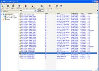
AXIS Camera Management - multiple cameras/large installations
AXIS Camera Management can automatically discover multiple Axis devices, show connection
status, manage firmware upgrades, and set IP addresses.
Automatic discovery
1. Check that the camera is connected to the network and that power has been applied.
2. Start AXIS Camera Management. When the camera appears in the window, right-click the link
and select Live View Home Page.
3. See page 13 for instructions on how to set the password.
Assign an IP address in a single device
1. Select one of the AXIS M31-VE Network Camera Series in AXIS
Camera Management and click the Assign IP button .
2. Select Assign the following IP address and enter the IP
address, the subnet mask, and default router the device will use.
3. Click OK.
Assign IP addresses in multiple devices
AXIS Camera Management speeds up the process of assigning IP
addresses to multiple devices, by suggesting IP addresses from a
specified range.
1. Select the devices you wish to configure (different models can be
selected) and click the Assign IP button .
2. Select Assign the following IP address range and enter the range
of IP addresses, the subnet mask, and default router the devices will use.
3. Click the OK button.AXIS M31-VE Network Camera Series Installation Guide Page 13
Set the password
To gain access to the product, the password for the default administrator user root must be set. This
is done in the Configure Root Password dialog, which is displayed when the network camera is
accessed for the first time.
To prevent network eavesdropping when setting the root password, this can be done via an
encrypted HTTPS connection, which requires an HTTPS certificate.
To set the password via a standard HTTP connection, enter it in the Configure Root Password
window.
ENGLISH
To set the password via an encrypted HTTPS connection, follow these steps:
1. Click the Create self-signed certificate button.
2. Provide the requested information and click OK. The certificate is created and the password can
now be set securely. All traffic to and from the network camera is encrypted from this point on.
3. Enter a password and then re-enter it to confirm the spelling. Click OK. The password has now
been configured.
To create an HTTPS connection, start by clicking
this button.
To configure the password directly via an
unencrypted connection, enter the password
here.
4. To log in, enter the user name “root” in the dialog as requested.
Note: The default administrator user name root cannot be deleted.
5. Enter the password as set above, and click OK. If the password is lost, the network camera must
be reset to the factory default settings. See page 17.
If required, click Yes to install AMC (AXIS Media Control), which allows viewing of the video stream
in Internet Explorer. You will need administrator rights on the computer to do this.
The Live View page of the network camera appears. The Setup link to the right gives you menu
options for customizing the camera.Page 14 AXIS M31-VE Network Camera Series Installation Guide
Adjust the focus
lens tool
Fit black rubber side to adjust focus
Pull the lens tool from the lens tool holder, turn it around and fit the black rubber side to the lens.
Adjust the focus. Check the image in the Live View page, and move the lens to the desired position
using the transparent side of the lens tool. See illustration under Hardware overview, on page 6.
After replacing the top cover, the image may appear slightly out of focus due to the optical effect
of the dome (especially in the case of tele/zoom lenses). To compensate, focus on an object slightly
closer than the intended area. If possible, position the top cover in front of the lens while adjusting
focus.
Complete the installation
To complete the installation, replace the top cover with care and tighten the captive screws. Ensure
that the rubber gasket in the top cover and the ridge it fits into in the bottom plate are dust-free.
Check the live view at this point to see if the weather shield on the top cover interferes with the
image. If it does, adjust the lens again as described above.
Changing the lens
To change the lens of the network camera:
1. Fit the black rubber side of the lens tool to the lens holder and unscrew the lens.
2. Remove the lens from the lens tool and fix the new lens to it.
3. Fit the new lens to the camera and tighten the lens into place.
4. Adjust the focus as described above.AXIS M31-VE Network Camera Series Installation Guide Page 15
Other methods of setting the IP address
All the methods listed the table below are enabled by default, and can be disabled.
Use in Notes
operating
system
UPnP™ Windows When enabled on your computer, the camera is automatically
detected and added to “My Network Places.”
ENGLISH
Bonjour MAC OSX Applicable to browsers with support for Bonjour. Navigate to the
(10.4 or later) Bonjour bookmark in your browser (e.g. Safari) and click on the link
to access the camera’s web pages.
AXIS All A free service from Axis that allows you to quickly and simply install
Dynamic DNS your camera. Requires an Internet connection with no HTTP proxy.
Service See www.axiscam.net for more information.
ARP/Ping All See below. The command must be issued within 2 minutes of
connecting power to the camera.
View DHCP All To view the admin pages for the network DHCP server, see the
server admin server’s own documentation.
pages
AXIS Video Hosting System (AVHS)
The camera can also be connected to an AVHS service for hosted video. If you have subscribed to an
AVHS service, follow the instructions in the Service Provider’s Installation Guide. For more
information and help to find a local AVHS Service Provider, go to www.axis.com/hosting
The camera owner authentication key is supplied with this product. The key is associated with the
camera’s unique serial number (S/N) as shown on the top of the label.
Note:
Save the key for future reference.Page 16 AXIS M31-VE Network Camera Series Installation Guide
Set the IP address with ARP/Ping
1. Acquire an IP address on the same network segment your computer is connected to.
2. Locate the serial number (S/N) on the camera’s label.
3. Open a command prompt on your computer and enter the following commands:
Windows syntax Windows example
arp -s arp -s 192.168.0.125 00-40-8c-18-10-00
ping -l 408 -t ping -l 408 -t 192.168.0.125
UNIX/Linux/Mac syntax UNIX/Linux/Mac example
arp -s temp arp -s 192.168.0.125 00:40:8c:18:10:00 temp
ping -s 408 ping -s 408 192.168.0.125
4. Check that the network cable is connected to the camera and then start/restart the camera, by
disconnecting and reconnecting power.
5. Close the command prompt when you see ‘Reply from 192.168.0.125: ...’ or similar.
6. In your browser type http:// in the Location/Address field and press Enter.
Notes:
• To open a command prompt in Windows: from the Start menu, select Run... and type cmd. Click OK.
• To use the ARP command on a Mac OS X, use the Terminal utility in Application > Utilities.AXIS M31-VE Network Camera Series Installation Guide Page 17
Resetting to the Factory Default Settings
This will reset all parameters, including the IP address, to the factory default settings:
1. Disconnect power from the camera.
2. Remove the top cover by loosening the 2 captive screws.
3. Press and hold the Control button and reconnect power (see Hardware overview, on page 6).
4. Keep the Control button pressed for about 15 seconds until the Status indicator flashes amber.
5. Release the Control button. The process is complete after about 1 minute (when the Status
indicator turns green). The network camera has been reset to the factory default settings. The
ENGLISH
default IP address is 192.168.0.90
6. Re-assign the IP address.
7. Refocus the camera.
It is also possible to reset parameters to factory default via the web interface. Go to Setup > System
Options > Maintenance.
Further information
The user’s manual is available from the Axis Web site at www.axis.com or from the Axis Network
Video Product CD supplied with this product.
Tip!
Visit www.axis.com/techsup to check if there is updated firmware available for your
network camera. To see the currently installed firmware version, click the Basic
Configuration menu item in the product’s web page.Mesures de sécurité
Lisez attentivement le présent guide d’installation avant d’installer le produit. Conservez le guide d’installation
si vous souhaitez le consulter ultérieurement.
ATTENTION !
• Pour éviter d’endommager le produit Axis, utilisez l’emballage d’origine ou un équivalent pour le
transporter.
• Stockez le produit Axis dans un environnement sec et aéré.
• Utilisez uniquement des outils manuels pour l’installation du produit Axis, l’utilisation d’outils électriques
ou l’usage excessif de la force risque de l’endommager.
• N’utilisez ni produits chimiques, ni substances caustiques, ni nettoyeurs aérosol. Utilisez un linge humide
pour le nettoyage.
• Utilisez uniquement des accessoires et des pièces de rechange fournis ou recommandés par Axis.
• Ne tentez pas de réparer le produit vous-même, contactez Axis ou votre revendeur Axis pour tout problème
lié au service.
IMPORTANT !
• Ce produit Axis doit être utilisé conformément aux lois et réglementations locales en vigueur.Série des caméras réseau AXIS M31-VE Guide d’installation Page 19
Guide d’installation pour la série AXIS
M31-VE
Ce guide d’installation vous explique comment installer les caméras réseau suivantes :
• AXIS M3113-VE
• AXIS M3114-VE
• AXIS M3113-VE Nocap
• AXIS M3114-VE Nocap
Pour toute autre question concernant l’utilisation du produit, reportez-vous au manuel de
l’utilisateur que vous trouverez sur le CD ci-joint ou sur le site www.axis.com/techsup
Procédure d’installation
FRANÇAIS
1. Vérifiez le contenu de l’emballage en le comparant à la liste ci-dessous.
2. Description du matériel. Reportez-vous à la page 21.
3. Installation du matériel. Reportez-vous à la page 23.
4. Attribution d’une adresse IP. Reportez-vous à la page
25. Important !
Ce produit doit être utilisé
5. Configuration du mot de passe. Reportez-vous à la page
conformément aux lois et
28.
réglementations locales en
6. Réglage de la mise au point. Reportez-vous à la page vigueur.
29.
7. Fin de l’installation. Reportez-vous à la page 30.
Contenu de l’emballage
Élément Modèles/variantes/remarques
Caméra réseau AXIS M3113-VE, AXIS M3114-VE
AXIS M3113-VE Nocap, AXIS M3114-VE Nocap
Outils Adaptateur à deux (2) couvercles
Outil de l’objectif
Outil du couvercle supérieur
Clé hexagonale
CD CD du produit de vidéo sur IP Axis comprenant une documentation, des
outils d’installation et des logiciels complémentairesPage 20 Série des caméras réseau AXIS M31-VE Guided’installation
Élément Modèles/variantes/remarques
Documentation imprimée Guide d’installation de la Série des caméras réseau AXIS M31-VE (le
présent document)
Gabarit de perçage
Étiquettes de numéro de série supplémentaires
Document de garantie d’AxisSérie des caméras réseau AXIS M31-VE Guide d’installation Page 21
Description du matériel
Voyants lumineux
Marque « 180 »
(haut de l’image)
Porte-objectif
Monture optique
Support optique
Bouton de commande
Utilisez les vis ici pour monter la caméra sur la surface de montage
FRANÇAIS
AXIS M31-VE
Protection étanche
Adaptateur
Câble Ethernet
Outil du couvercle supérieur
AXIS M31-VE Nocap
Trou pour le montage
de la caméra sur le support
Outil de l’objectif
Côté noir en caoutchouc (pour le réglage de la mise au point)
Côté transparent
(pour le réglage du champ de vision)
Couvercles de câble Outil de l’objectif pour le réglage du champ de vision
Outil de l’objectif pour le réglage de la mise au pointPage 22 Série des caméras réseau AXIS M31-VE Guided’installation
Voyants lumineux
(DEL) Couleur Indication
Réseau Vert Continu en cas de connexion à un réseau de 100 Mbit/s. Clignote en cas d’activité
réseau.
Orange Continu en cas de connexion à un réseau de 10 Mbit/s. Clignote en cas d’activité
réseau.
Éteint Pas de connexion au réseau. Remarque : le voyant de réseau peut être configuré
pour être éteint au cours du fonctionnement normal. Pour ce faire, cliquez sur
Setup > System Options > LED settings (Configuration > Options système >
Paramètres des voyants). Reportez-vous à l’aide en ligne pour plus
d’informations.
État Vert Vert continu en cas de fonctionnement normal.
Remarque : le voyant d’état peut être configuré pour être éteint pendant le
fonctionnement normal ou pour clignoter uniquement en cas d’accès à la caméra.
Pour ce faire, cliquez sur Setup > System Options > LED settings (Configuration
> Options système > Paramètres des voyants). Reportez-vous à l’aide en ligne
pour plus d’informations.
Orange Continu pendant le démarrage, la réinitialisation des paramètres d’usine ou la
restauration des paramètres.
Rouge Clignote lentement en cas d’échec de la mise à niveau.
Aliment Vert Fonctionnement normal.
ation
Orange Clignote en vert/orange pendant la mise à niveau des micrologiciels.
Connecteurs de l’unité
Connecteur réseau - Connecteur mâle Ethernet RJ-45 pour 10BaseT/100BaseTX avec câble de 3
mètres. Prend en charge l’alimentation par Ethernet (PoE).Série des caméras réseau AXIS M31-VE Guide d’installation Page 23
Installation du matériel
1. Enlevez le couvercle supérieur de la caméra en
desserrant les deux vis. Insérez ensuite l’outil
du couvercle supérieur dans la fente du
couvercle inférieur et soulevez-le.
2. Selon le type d’installation requise, suivez les instructions appropriées ci-dessous.
Monter la caméra sans l’adaptateur
1. Ajustez le gabarit de perçage sur la surface de montage de façon à
ce que l’objectif de la caméra soit dirigé dans la bonne direction,
puis percez quatre trous pour les vis et un trou pour le câble.
2. Alignez les emplacements pour les vis de la caméra avec les trous
faits dans la surface de montage, et fixez la caméra avec quatre
FRANÇAIS
vis.
Remarque :
Chaque tête de vis avec rondelle doit mesurer 5 mm de haut et 7 mm de
diamètre au maximum.
N’utilisez pas de vis à tête fraisée.
3. Connectez le câble réseau au commutateur PoE.
Monter la caméra avec l’adaptateur (câbles le long du mur)
1. Placez l’adaptateur sur la surface de montage (mur ou plafond) et positionnez la fente pour le
câble à l’endroit approprié.
2. Fixez l’adaptateur avec quatre vis appropriées au matériau de la surface.
3. Faites glisser le câble Ethernet de la caméra le long de
la fente pour câble dans l’adaptateur.
4. Appuyez sur le couvercle de câble destiné au câblage
latéral pour l’insérer dans la fente située sur le côté de
l’adaptateur.
5. Placez la caméra sur l’adaptateur et tournez la caméra
pour que l’objectif soit dirigé dans la bonne direction.
6. Ajustez les fentes pour les vis de la caméra pour Fente pour Couvercle
câble de câble
qu’elles soient alignées avec les trous pour les vis de
l’adaptateur, puis fixez les quatre vis (couple < 2,5
Nm). Couvercle de câble
7. Connectez le câble réseau au commutateur PoE.Page 24 Série des caméras réseau AXIS M31-VE Guided’installation
Monter la caméra avec l’adaptateur (câbles dans le mur et montage sur support)
1. Faites glisser le câble Ethernet de la caméra Fente pour câble
dans la fente pour câble. Ajustez le câble pour
qu’il s’insère dans le trou.
2. Appuyez sur le couvercle de câble approprié
pour l’insérer dans la fente sur le côté de
l’adaptateur.
3. Fixez l’adaptateur avec quatre vis appropriées Trou pour câble
au matériau de la surface.
4. Suivez les étapes 5 à 7 ci-dessus.
Couvercle de câble
Ajuster l’orientation de l’objectif
Insérez l’outil de l’objectif dans le porte-objectif et ajustez la position de l’objectif en orientant sa
poignée dans la direction souhaitée (voir l’illustration à la page 21). Cette opération peut se faire
verticalement de 0 à 90 degrés (assurez-vous que la protection étanche ne gène pas la vue) et de 30
degrés vers la gauche ou vers la droite de chaque côté par incrément de cinq.
Le porte-objectif peut également pivoter pour s’ajuster à l’image.
Alignez les nervures horizontalement sur le dispositif de l’objectif pour que
l’image soit aussi alignée horizontalement.
Alignez les nervures
horizontalement
Remarque :
La marque « 0 » sur le porte-objectif indique le bas de
l’image et la marque « 180 » indique le haut de l’image,
consultez Description du matériel, à la page 21. Si la
Ligne
caméra est montée à l’envers, ajustez-la de façon à ce
que la marque « 0 » soit en haut et la marque « 180 » Ligne
sous l’objectif.
La ligne à l’intérieur de la partie inférieure du porte-objectif doit être alignée avec la ligne au centre de
la monture optique.Série des caméras réseau AXIS M31-VE Guide d’installation Page 25
Attribution d’une adresse IP
La Série des caméras réseau AXIS M31-VE est conçue pour être utilisée sur un réseau Ethernet et
nécessite une adresse IP pour y accéder. Aujourd’hui, la plupart des réseaux sont équipés d’un
serveur DHCP qui attribue automatiquement des adresses IP aux dispositifs connectés. Si votre
réseau en est dépourvu, la Série des caméras réseau AXIS M31-VE utilisera 192.168.0.90 comme
adresse IP par défaut.
Si vous souhaitez définir une adresse IP sous Windows, nous vous recommandons d’utiliser
l’application AXIS IP Utility ou AXIS Camera Management. Ces deux applications gratuites sont
disponibles sur le CD accompagnant votre produit de vidéo sur IP Axis. Vous pouvez également les
télécharger à partir du site www.axis.com/techsup. Choisissez la méthode qui vous convient le
mieux en fonction du nombre de caméras à installer.
Méthode Recommandée pour Système d’exploitation
FRANÇAIS
AXIS IP Utility Caméra unique Windows
Voir page 26 Petites installations
AXIS Camera Plusieurs caméras Windows 2000
Management Grandes installations Windows XP Pro
Voir page 27 Installation sur un autre Windows 2003 Server
sous-réseau Windows Vista
Remarques :
• Si vous n’arrivez pas à configurer l’adresse IP, vérifiez qu’aucun pare-feu ne bloque l’opération.
• Pour connaître les autres méthodes d’attribution ou de détection de l’adresse IP, par exemple sous
d’autres systèmes d’exploitation, reportez-vous à la page 31.Page 26 Série des caméras réseau AXIS M31-VE Guided’installation AXIS IP Utility - Caméra unique et petite installation AXIS IP Utility recherche et affiche automatiquement les périphériques Axis présents sur votre réseau. Cette application permet également de définir manuellement une adresse IP statique. Vous trouverez l’application AXIS IP Utility sur le CD accompagnant votre produit de vidéo sur IP Axis. Vous pouvez également la télécharger à partir du site www.axis.com/techsup. Notez que vous devez installer la caméra réseau sur le même segment de réseau (sous-réseau physique) que l’ordinateur exécutant l’application AXIS IP Utility. Détection automatique 1. Vérifiez que la caméra réseau est connectée au réseau et qu’elle est sous tension. 2. Lancez AXIS IP Utility. 3. Lorsque l’icône de la caméra apparaît dans la fenêtre, cliquez deux fois dessus pour ouvrir la page d’accueil correspondante. 4. Reportez-vous à la page 28 pour savoir configurer le mot de passe. Attribution manuelle de l’adresse IP (facultatif) 1. Trouvez une adresse IP non utilisée sur le même segment de réseau que celui de votre ordinateur. 2. Sélectionnez AXIS M3113/AXIS M3114 dans la liste.
Série des caméras réseau AXIS M31-VE Guide d’installation                                   Page 27

3. Cliquez sur le bouton      Assign new IP address to selected device (Attribuer une nouvelle
   adresse IP au périphérique sélectionné) et saisissez l’adresse IP.
4. Cliquez sur le bouton Assign (Attribuer) et suivez les instructions.
5. Cliquez sur le bouton Home Page (Page d’accueil) pour accéder aux pages Web de la caméra.
6. Reportez-vous à la page 28 pour savoir comment configurer le mot de passe.

AXIS Camera Management - Plusieurs caméras et grandes installations

AXIS Camera Management peut détecter automatiquement plusieurs périphériques Axis, afficher
leur état de connexion, gérer les mises à niveau du micrologiciel et configurer les adresses IP.

                                                                                                      FRANÇAIS
Détection automatique

1. Vérifiez que la caméra est connectée au réseau et qu’elle est sous tension.
2. Lancez AXIS Camera Management. Lorsque l’icône de la caméra apparaît dans la fenêtre,
   cliquez sur le lien à l’aide du bouton droit de la souris et sélectionnez Live View Home Page
   (Page d’accueil – Vidéo en direct).
3. Reportez-vous à la page 28 pour savoir comment configurer le
   mot de passe.

Attribution d’une adresse IP à un seul périphérique

1. Sélectionnez l’une des caméras de la Série des caméras réseau
   AXIS M31-VE dans l’application AXIS Camera Management,
   puis cliquez sur le bouton Assign IP (Attribuer une adresse
    IP).
2. Sélectionnez Assign the following IP address (Attribuer l’adresse IP suivante) et saisissez
   l’adresse IP, le masque de sous-réseau et le routeur par défaut que le périphérique utilisera.
3. Cliquez sur OK.
Page 28 Série des caméras réseau AXIS M31-VE Guided’installation
Attribution d’adresses IP à plusieurs périphériques
AXIS Camera Management accélère le processus d’attribution
d’adresses IP à plusieurs périphériques en suggérant des adresses IP
dans une plage spécifiée.
1. Sélectionnez les périphériques à configurer (il peut s’agir de
modèles différents), puis cliquez sur le bouton Assign IP (Attribuer
une adresse IP) .
2. Sélectionnez Assign the following IP address range (Attribuer la plage d’adresses IP suivante)
et saisissez la plage d’adresses IP, le masque de sous-réseau et le routeur par défaut que les
périphériques utiliseront.
3. Cliquez sur le bouton OK.
Configuration du mot de passe
Pour accéder au produit, le mot de passe de l’administrateur root par défaut doit être configuré.
Pour ce faire, utilisez la boîte de dialogue Configure Root Password (Configurer le mot de passe
root) qui s’affiche lors du premier accès à la caméra réseau.
Pour éviter les écoutes électroniques lors de la configuration du mot de passe root, utilisez une
connexion HTTPS cryptée nécessitant un certificat HTTPS.
Pour configurer le mot de passe avec une connexion HTTP standard, saisissez-le dans la fenêtre
Configure Root Password (Configurer le mot de passe root).
Pour configurer le mot de passe avec une connexion HTTPS cryptée, procédez comme suit :
1. Cliquez sur le bouton Create self-signed certificate (Créer un certificat autosigné).
2. Saisissez les informations demandées, puis cliquez sur OK. Le certificat est créé et le mot de
passe peut maintenant être configuré en toute sécurité. Tout le trafic vers et depuis la caméra
réseau est désormais crypté.Série des caméras réseau AXIS M31-VE Guide d’installation Page 29
3. Saisissez un mot de passe, puis saisissez-le à nouveau pour le confirmer. Cliquez sur OK. Le mot
de passe est maintenant configuré.
Pour créer une connexion HTTPS, cliquez sur ce
bouton.
FRANÇAIS
Pour configurer directement le mot de passe par
le biais d’une connexion non cryptée, saisissez le
mot de passe dans cette section.
4. Pour vous connecter, saisissez le nom d’utilisateur « root » dans la boîte de dialogue comme
demandé.
Remarque : Le nom de l’administrateur par défaut est « root » et ne peut pas être supprimé.
5. Saisissez le mot de passe défini précédemment et cliquez sur OK. Si vous avez oublié votre mot
de passe, vous devrez rétablir les paramètres d’usine de votre caméra réseau. Reportez-vous à la
page 33.
Si le système vous le demande, cliquez sur Yes (Oui) pour installer AMC (AXIS Media Control) afin de
pouvoir visualiser les flux de données vidéo dans Internet Explorer. Pour ce faire, vous devrez être
connecté à l’ordinateur avec des droits d’administrateur.
La page Live View (Vue en direct) de la caméra réseau s’affiche. Le lien Setup (Configuration) à
droite vous donne accès aux options de menu pour adapter la caméra à vos besoins.
Régler la mise au point
Outil de l’objectif
Insérez le côté noir en caoutchouc pour régler la mise au pointPage 30 Série des caméras réseau AXIS M31-VE Guided’installation
Enlevez l’outil de l’objectif du porte-objectif, retournez-le et intégrez le côté noir en caoutchouc à
l’objectif. Réglez la mise au point. Vérifiez l’image dans la page Live View (Vue en direct) et placez
l’objectif dans la position souhaitée, en utilisant le côté transparent du l’outil de l’objectif. Voir
l’illustration dans Description du matériel, à la page 21.
Après avoir replacé le couvercle supérieur, l’image peut être légèrement floue en raison de l’effet
optique du dôme (particulièrement dans le cas d’objectifs avant/zoom). Pour compenser ce défaut,
effectuez la mise au point sur un objet légèrement plus proche que la zone cible. Si possible, placez
le couvercle supérieur devant l’objectif tout en réglant la mise au point.
Fin de l’installation
Pour terminer l’installation, replacez le couvercle supérieur avec précaution et serrez les vis
imperdables. Assurez-vous que le joint en caoutchouc du couvercle supérieur et la strie dans
laquelle il s’emboîte dans le plateau inférieur ne présentent aucune poussière.
Vérifiez alors la vue en temps réel pour voir si la protection étanche sur le couvercle supérieur
interfère avec l’image. Si tel est le cas, réglez de nouveau l’objectif comme indiqué plus haut.
Remplacement de l’objectif
Pour remplacer l’objectif de la caméra réseau :
1. Ajustez le côté noir en caoutchouc de l’outil de l’objectif au porte-objectif et dévissez l’objectif.
2. Enlevez l’objectif de l‘outil de l’objectif et fixez-y le nouvel objectif.
3. Ajustez le nouvel objectif à la caméra et serrez l’objectif pour le maintenir solidement en place.
4. Réglez la mise au point comme indiqué plus haut.Série des caméras réseau AXIS M31-VE Guide d’installation Page 31
Autres méthodes de définition de l’adresse IP
Toutes les méthodes énumérées dans le tableau ci-dessous sont activées par défaut, et peuvent être
désactivées.
Utiliser sous le Remarques
système
d’exploitation
UPnP™ Windows Lorsque la caméra est activée sur votre ordinateur, elle est détectée
et ajoutée automatiquement au dossier Favoris réseau.
Bonjour MAC OSX Pour les navigateurs compatibles avec Bonjour. Accédez au signet de
(10.4 ou version Bonjour dans votre navigateur (par exemple Safari), puis cliquez sur
ultérieure) le lien permettant d’accéder aux pages Web de la caméra.
Tous Service Axis gratuit permettant d’installer rapidement et facilement
FRANÇAIS
AXIS
Dynamic DNS votre caméra. Nécessite une connexion Internet sans proxy HTTP.
Service Pour plus d’informations, rendez-vous sur www.axiscam.net.
ARP/Ping Tous Voir ci-dessous. La commande doit être saisie dans les 2 minutes
suivant la mise sous tension de la caméra.
Affichage Tous Pour consulter les pages d’administration du serveur DHCP réseau,
des pages reportez-vous à la documentation du serveur.
d’administrat
ion du
serveur DHCP
AXIS Video Hosting System (AVHS)
La caméra peut aussi être connectée à un serveur AVHS pour les vidéos reçues. Si vous vous êtes
inscrit à un service AVHS, suivez les instructions décrites dans le Guide d’installation du fournisseur
de service. Pour obtenir des renseignements supplémentaires et trouver un fournisseur de service
AVHS, consultez le site www.axis.com/hosting
La clé d’authentification du propriétaire de la caméra est fournie avec ce produit. Elle est associée
au numéro de série (S/N) unique de la caméra, comme décrit sur le haut de l’étiquette.
Remarque :
Enregistrez la clé pour référence ultérieure.Page 32 Série des caméras réseau AXIS M31-VE Guided’installation
Définition de l’adresse IP à l’aide d’ARP/Ping
1. Trouvez une adresse IP sur le même segment de réseau que celui de votre ordinateur.
2. Repérez le numéro de série (S/N) sur l’étiquette de la caméra.
3. Ouvrez une invite de commande sur votre ordinateur et saisissez les commandes suivantes :
Syntaxe pour Windows Exemple pour Windows
arp -s arp -s 192.168.0.125 00-40-8c-18-10-00
ping -l 408 -t ping -l 408 -t 192.168.0.125
Syntaxe pour UNIX/Linux/Mac Exemple pour UNIX/Linux/Mac
arp -s temp arp -s 192.168.0.125 00:40:8c:18:10:00 temp
ping -s 408 ping -s 408 192.168.0.125
4. Vérifiez que le câble réseau est connecté à la caméra, puis démarrez/redémarrez cette dernière
en débranchant puis en rebranchant l’alimentation.
5. Fermez l’invite de commande lorsque le message « Reply from 192.168.0.125:... » (Réponse de
192.168.0.125 : ...) ...’ ou un message similaire s’affiche.
6. Dans votre navigateur, tapez http:// dans le champ Emplacement/Adresse, puis
appuyez sur la touche Entrée.
Remarques :
• Pour ouvrir une invite de commande sous Windows : dans le menu Démarrer, sélectionnez Exécuter… et
tapez cmd. Cliquez sur OK.
• Pour utiliser la commande ARP sous Mac OS X, utilisez l’utilitaire Terminal dans Application >
Utilitaires.Série des caméras réseau AXIS M31-VE Guide d’installation Page 33
Rétablissement des paramètres d’usine
Procédez comme suit pour rétablir les paramètres par défaut définis en usine et réinitialiser
l’adresse IP :
1. Mettez la caméra hors tension.
2. Enlevez le couvercle supérieur en desserrant les deux vis imperdables.
3. Maintenez le bouton de commande enfoncé tout en remettant l’appareil sous tension
(reportez-vous à la Description du matériel, à la page 21).
4. Maintenez le bouton de commande enfoncé jusqu’à ce que le voyant d’état devienne l’orange
(cela prend environ 15 secondes).
5. Relâchez le bouton de commande. Le processus se termine après environ 1 minute (lorsque le
voyant d’état devient vert). Les paramètres d’usine de la caméra réseau ont été rétablis.
L’adresse IP par défaut est 192.168.0.90
6. Attribuez à nouveau l’adresse IP.
FRANÇAIS
7. Effectuez de nouveau la mise au point de la caméra.
Il est également possible de rétablir les paramètres d’usine à partir de l’interface Web. Cliquez sur
Setup > System Options > Maintenance (Configuration > Options système > Maintenance).
Plus d’informations
Le manuel de l’utilisateur est disponible sur le site Web d’Axis (www.axis.com) et sur le CD du
produit de vidéo sur IP Axis fourni avec ce produit.
Conseil :
Consultez le site www.axis.com/techsup pour vérifier si des micrologiciels à jour sont
disponibles pour votre caméra réseau. Pour connaître la version du micrologiciel
actuellement installée, cliquez sur la commande du menu Basic Configuration
(Configuration de base) dans la page Web du produit.Sicherheitsvorkehrungen
Bitte lesen Sie zunächst diese Installationsanleitung vollständig durch, bevor Sie mit der Installation Ihres
Produkts beginnen. Halten Sie die Installationsanleitung bereit, falls Sie darauf zurückgreifen müssen.
VORSICHT!
• Transportieren Sie das Axis-Produkt nur in der Originalverpackung bzw. in einer vergleichbaren Verpackung,
damit das Produkt nicht beschädigt wird.
• Lagern Sie das Axis-Produkt in einer trockenen und belüfteten Umgebung.
• Verwenden Sie keine elektrischen Werkzeuge zur Montage des Axis-Produkts, da diese das Produkt
beschädigen könnten.
• Verwenden Sie keine chemischen, ätzenden oder Aerosol-Reinigungsmittel. Verwenden Sie zur Reinigung
ein feuchtes Tuch.
• Verwenden Sie nur Zubehör und Ersatzteile, die von Axis empfohlen bzw. bereitgestellt wurden.
• Versuchen Sie nicht, das Produkt selbst zu reparieren. Wenden Sie sich bei Service-Angelegenheiten an Axis
oder an Ihren Axis-Händler.
WICHTIG!
• Verwenden Sie dieses Axis-Produkt unter Beachtung der geltenden rechtlichen Bestimmungen.AXIS M31-VE Netzwerk-Kamera-Serie Installationsanleitung Seite 35
Installationsanleitung für die AXIS
M31-VE Serie
In dieser Anleitung wird die Installation der folgenden Netzwerk-Kameras beschrieben:
• AXIS M3113-VE
• AXIS M3114-VE
• AXIS M3113-VE Nocap
• AXIS M3114-VE Nocap
Alle weiteren Hinweise zur Verwendung des Produkts finden Sie im Benutzerhandbuch, das auf der
mitgelieferten CD oder auf unserer Website unter „www.axis.com/techsup“ zur Verfügung steht.
Installationsschritte
1. Prüfen Sie, ob alle in der nachfolgenden Liste aufgeführten Komponenten vorhanden sind.
2. Sehen Sie sich die Hardwareübersicht an. Siehe Seite 36.
3. Installieren Sie die Hardware. Siehe Seite 38.
4. Weisen Sie eine IP-Adresse zu. Siehe Seite 41.
Wichtig!
DEUTSCH
5. Legen Sie das Kennwort fest. Siehe Seite 44.
Verwenden Sie dieses Produkt
6. Stellen Sie die Bildschärfe ein. Siehe Seite 45. unter Beachtung der geltenden
7. Schließen Sie die Installation ab. Siehe Seite 46. rechtlichen Bestimmungen.
Inhalt des Produktpakets
Komponente Modelle/Varianten/Anmerkungen
Netzwerk-Kamera AXIS M3113-VE, AXIS M3114-VE
AXIS M3113-VE Nocap, AXIS M3114-VE Nocap
Tools Adapter mit (2) Klemmen
Objektivwerkzeug
Werkzeug für obere Abdeckung
Inbusschlüssel
CD-ROM CD für Axis-Netzwerkvideoprodukte einschließlich
Installationswerkzeugen und anderer Software sowie
Produktdokumentation
Gedruckte Dokumente AXIS M31-VE Netzwerk-Kamera-Serie Installationsanleitung (dieses
Dokument)
Bohrschablone
Zusätzliche Aufkleber mit Seriennummer
Axis-GarantieerklärungSeite 36 AXIS M31-VE Netzwerk-Kamera-Serie Installationsanleitung
Hardwareübersicht
LED-Anzeigen
180°-Markierung
(Bildoberseite)
Objektivhalter
Optikanschluss
Optikhalter
Steuertaste
Bringen Sie die Schrauben hier an, um die Kamera
an der Montageoberfläche zu befestigen
AXIS M31-VE
Wetterschutz
Adapter
Ethernet-Kabel
Werkzeug für obere Abdeckung
AXIS M31-VE Nocap
Öffnung zur Montage der
Kamera auf einem Standfuß
Objektivwerkzeug
Schwarze Gummiseite (für das Einstellen der Bildschärfe)
Transparente Seite
(für die Bildanpassung)
Kabelklemmen Objektivwerkzeug für die Bildanpassung
Objektivwerkzeug für die Einstellung der BildschärfeAXIS M31-VE Netzwerk-Kamera-Serie Installationsanleitung Seite 37
LED-Anzeigen
LED Farbe Bedeutung
Netz- Grün Leuchtet dauerhaft bei Verbindung mit einem 100-MBit/s-Netzwerk. Blinkt bei
werk Netzwerkaktivität.
Gelb Leuchtet dauerhaft bei Verbindung mit einem 10-MBit/s-Netzwerk. Blinkt bei
Netzwerkaktivität.
Leuchtet Keine Netzwerkverbindung vorhanden. Hinweis: Die Netzwerk-LED kann so
nicht konfiguriert werden, dass sie bei normalem Betrieb nicht leuchtet. Diese
Einstellung können Sie unter „Setup > System Options > LED settings“ (Setup >
Systemoptionen > LED-Einstellungen) vornehmen. Weitere Informationen
hierzu finden Sie in der Online-Hilfe.
Status Grün Leuchtet bei Normalbetrieb konstant grün.
Hinweis: Die Status-LED kann so konfiguriert werden, dass sie bei normalem
Betrieb nicht leuchtet oder nur dann blinkt, wenn auf die Kamera zugegriffen
wird. Diese Einstellung können Sie unter „Setup > System Options > LED
settings“ (Setup > Systemoptionen > LED-Einstellungen) vornehmen. Weitere
Informationen hierzu finden Sie in der Online-Hilfe.
DEUTSCH
Gelb Leuchtet konstant beim Einschalten und beim Wiederherstellen der
Werkseinstellungen bzw. von vorherigen Einstellungen.
Rot Blinkt langsam bei Aktualisierungsfehler.
Betriebs Grün Normaler Betrieb.
anzeige
Gelb Blinkt grün/gelb während Firmware-Aktualisierung.
Geräteanschlüsse
Netzwerkanschluss - RJ-45-Ethernet-Stecker für 10BaseT/100BaseTX mit 3-Meter-Kabel.
Unterstützt Power over Ethernet.Vous pouvez aussi lire