OPTEASTAR 2+ VERSION SIMPLE SINGLE VERSION - 42U 600X300 19'' - Nexans
←
→
Transcription du contenu de la page
Si votre navigateur ne rend pas la page correctement, lisez s'il vous plaît le contenu de la page ci-dessous
NOTICE / INSTRUCTIONS                                                         Document : ABS1513/A
                                                                              Date : 09/10/2018

                                        OPTEASTAR 2+
                                        VERSION SIMPLE
                                        SINGLE VERSION

      42U 600X300 19’’                   42U 800X300 19’’                        45U 900X300 19’’

   Tous les schémas, dessins, spécifications, plans et détails de poids, tailles et dimensions figurant dans la
   documentation technique ou commerciale de Nexans ont un caractère purement indicatif et ne sauraient
           engager Nexans ou être traités comme constitutifs d’une garantie de la part de Nexans.
  All drawings, designs, specifications, plans and particulars of weights, size and dimensions contained in the
 technical or commercial documentation of Nexans is indicative only and shall not be binding on Nexans or be
                         treated as constituting a representation on the part of Nexans.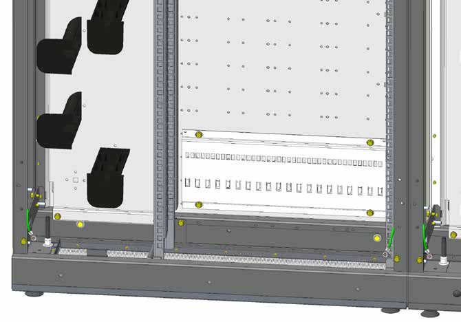
OPTEASTAR 2+

                                    Table des matières
                                     Table Of Contents
1.     INTRODUCTION
       OVERVIEW........................................................................................................4
1.1. PRÉSENTATION DU PRODUIT
     PRODUCT PRESENTATION......................................................................................... 4
1.2. CARACTÉRISTIQUES TECHNIQUES
     TECHNICAL CHARACTERISTICS.................................................................................. 5
1.3. ACCESSOIRES
     ACCESSORIES............................................................................................................ 6
2.     OPÉRATIONS PRÉLIMINAIRES
       PRELIMINARY OPERATIONS.............................................................................8
2.1. RETRAIT DES BAIES DE LA PALETTE
     CABINETS REMOVAL FROM THE PALLET..................................................................... 8
2.2. JUMELAGE DES BAIES
     CABINETS PAIRING.................................................................................................... 9
2.3. FIXATION
     FIXATION................................................................................................................. 11
2.4. MISE À LA TERRE
     GROUNDING.......................................................................................................... 13
3.     INSTALLATION DES ACCESSOIRES
       ACCESSORIES INSTALLATION.........................................................................14
3.1. KIT PLAQUE SUPPORT OMEGA
     OMEGA SUPPORT PLATE KIT................................................................................... 14
3.2. KIT ÉQUERRE DE BRIDAGE
     CLAMPING BRACKET KIT......................................................................................... 15
3.3. KIT ANNEAUX DE LOVAGE
     COILING RINGS KIT................................................................................................. 16
3.4. KIT ANNEAUX PASSE-FILS
     GUIDING RINGS KIT................................................................................................ 17
3.5. KIT ANNEAUX À VOLET
     SHUTTER RINGS KIT................................................................................................. 17
3.6. CHEMIN DE CÂBLES HORIZONTAL 2U 19’’
     2U 19’’ HORIZONTAL CABLEWAY............................................................................ 18
3.7. KITS TOITS
     ROOF KITS.............................................................................................................. 19
4.     MISE EN PLACE DES CÂBLES
       CABLES INSTALLATION...................................................................................20

ABS1513/A                                                                                                                   2/24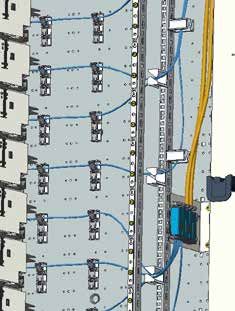
OPTEASTAR 2+

5.     SCHÉMAS DE BRASSAGE
       PATCHING SCHEMATICS.................................................................................21
5.1. BAIE SEULE
     SINGLE CABINET..................................................................................................... 21
5.2. BAIES DOS-À-DOS
     BACK-TO-BACK CABINETS....................................................................................... 22

                                                                                               8mm

ABS1513/A                                                                                                             3/24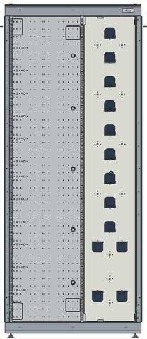
OPTEASTAR 2+

1.    INTRODUCTION
      OVERVIEW
1.1. Présentation du produit
     Product presentation

1-    2 flancs amovibles                      1-    2 removable flanks
2-    1 zone de lovage des surlongueurs de    2-    A coiling area for patchcords overlengths
      cordons avec demi tambours                    with half drums
3-    2 toits haut et bas interchangeables    3-    2 interchangeable up and bottom roofs
      (voir 3.7)                                    (see 3.7)
4-    1 ou 2 portes asymétriques              4-    1 or 2 asymmetrical doors
5-    4 pieds réglables                       5-    4 adjustable feet
6-    1 habillage arrière                     6-    A rear panel
7-    1 plaque de fond perforée pour la       7-    A perforated bottom plate for tubes and
      gestion des tubes ou câbles                   cables management
8-    4 profils d’angle                       8-    4 profiles for corners
9-    1 point de mise à la terre (voir 2.4)   9-    A grounding point (see 2.4)
10-   2 cadres haut et bas monoblocs soudés   10-   2 up and down welded frames
11-   1 rack 19’’ avec montants 42U ou 45U.   11-   A 19’’ rack with 42U or 45U frame.

ABS1513/A                                                                               4/24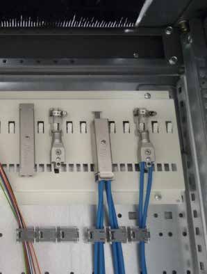
OPTEASTAR 2+

1.2. Caractéristiques techniques
     Technical characteristics

    42U 600X300 19’’               42U 800X300 19’’                       45U 900X300 19’’
   sans zone de lovage         avec zone de lovage simple            avec zone de lovage en « W »
   without coiling zone          with simple coiling zone                with ‘ W’ coiling zone

         Rack à gauche (charnière à droite)/rack à droite (charnière à gauche)
                     Left rack (right hinge)/right rack (left hinge)
                          Entrées de câbles par le haut/par le bas
                                  Upper/lower cable entry
                             Porte pleine/avec fenêtre plexiglass
                              Full door/with plexiglass window

     Porte avec serrure triangle de 8/serrure clé
        Door with 8mm triangle lock/key lock

     Flancs avec serrure triangle de 8/serrure
                  clé/Snap-Lock
     Flanges with 8mm triangle lock/key lock/
                    Snap-Lock

ABS1513/A                                                                                       5/24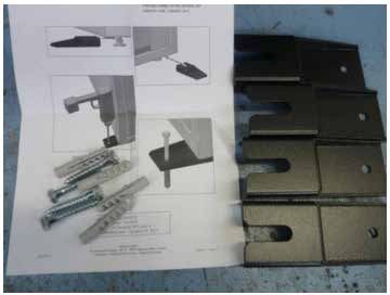
OPTEASTAR 2+

1.3. Accessoires
     Accessories

            La liste des accessoires fournis dépend       The list of accessories provided depends
            de la configuration choisie.                  on the selected configuration.

            x4
                                                     x2                                      x4

  Kit de jumelage dos-à-dos            Kit de jumelage par le toit         Kit de fixation plafond
   Back-to-back pairing kit                  Roof pairing kit                Ceiling fixation kit

                                                                                    x2

Kit équerre de bridage droite/gauche             Kit d’ancrage au sol           Kit de fixation murale
 Right/left side clamping bracket kit             Ground fixation kit             Wall mounting kit

                                           x6                                 x10
   Kit câbles de masse pour flancs          Kit anneaux de lovage           Kit anneaux passe-fils
   Grounding kit for side panels                Coiling rings kit              Guiding rings kit

                                          x4

                                Kit chemin de câbles horizontal 2U 19’’
                                     2U 19’’ horizontal cableway kit

ABS1513/A                                                                                         6/24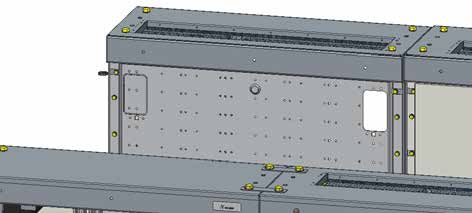
OPTEASTAR 2+

                         /                        900X300

                                                      /

                                                  800X300
                                                      /
                                                  600X300
                                                      /
                                                  300X300
                                                      +

                                               x4

                                 Kit toit plein/à brosse et ses accessoires
                               Full roof/roof with brush kit with accessories

                                                Permet une utilisation          Allows back-to-back
                                                des baies en dos-à-             use of the cabinets and
                                                dos et le transfert de          patchcords transfer
                                                cordons d’une baie à            from one cabinet to
                                                l’autre.                        the other.

   Kit profil passe-fils PP8
   PP8 cable guide profile

                    x1                                            x3
                    Kit plaque support OMEGA pour              Kit 3 anneaux à volet
                      BAEP avec 20 emplacements                3 rings with shutter kit
                    OMEGA support plate kit for BAEP
                           with 20 fixation slots

ABS1513/A                                                                                             7/24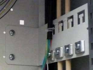
OPTEASTAR 2+

2.   OPÉRATIONS PRÉLIMINAIRES
     PRELIMINARY OPERATIONS
2.1. Retrait des baies de la palette
     Cabinets removal from the pallet

x4

x4

ABS1513/A                                        8/24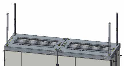
OPTEASTAR 2+

2.2. Jumelage des baies
     Cabinets pairing
2.2.1. Côte à côte
       Side-by-side

                      Flancs
                       Side
                      panels

                               Aligner à l’aide des
                                 pieds réglables
                                  Align using the
                                  adjustable feet

                                 x4
                                      Kit de jumelage par le toit
                                            Roof pairing kit

ABS1513/A                                                           9/24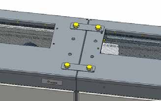
OPTEASTAR 2+

2.2.2. Dos à dos
       Back-to-back

            Si un passage entre deux baies est    If a cableway between two cabinets is
            prévu :                               planned:
            1. Enlever l’habillage arrière de     1. Remove the rear cover of each
                chaque baie.                           cabinet.
            2. Dégager les zones de passage des   2. Clear the patchcords routing areas.
                cordons.

                x8

        Profil passe-fils
        Wire-pass profile

ABS1513/A                                                                            10/24
OPTEASTAR 2+
x4 Kit jumelage dos-à-dos
Back-to-back pairing kit
Même procédure en bas
Same procedure at the bottom
Kit de jumelage
par le toit
Roof pairing kit
Même procédure à droite
Same procedure at the right
2.3. Fixation
Fixation
2.3.1. Fixation murale
Wall mounting
Kit de fixation murale
Wall mounting kit
Même procédure à droite
Same procedure at the right
ABS1513/A 11/24OPTEASTAR 2+
2.3.2. Fixation au plafond
Ceiling mounting
Assembler les cornières selon la
x4 hauteur du plafond
Mount the angle irons according
to ceiling height
Kit de fixation plafond
Ceiling fixation kit
x4
2.3.3. Fixation au sol
Ground mounting
Se reporter aux instructions fournies avec le Refer to the instructions provided with the
matériel. equipment.
Kit d’ancrage au sol
Ground fixation kit
ABS1513/A 12/24OPTEASTAR 2+
2.4. Mise à la terre
Grounding
Baie 1
Cabinet 1 Baie 2
Cabinet 2
Fig. Liaison entre deux baies Fig. Mise à la terre des portes
Connection between two cabinets Doors grounding
Kit câbles de masse pour flancs
Grounding kit for side panels
Fig. Mise à la terre des flancs Fig. Mise à la terre de l’ensemble
Side panels grounding Assembly grounding
Suivant According
spécification to customer
client. specification.
ABS1513/A 13/24OPTEASTAR 2+
3. INSTALLATION DES ACCESSOIRES
ACCESSORIES INSTALLATION
3.1. Kit plaque support OMEGA
OMEGA support plate kit
La plaque support intègre la fixation The support plate provides OMEGA direct
directe OMEGA des épanouisseurs. fastening for fanout devices.
Fixation en haut ou en bas de la Upper or lower fastening in the cabinet,
baie, selon l’entrée des câbles. depending on the cables entry.
ABS1513/A 14/24OPTEASTAR 2+
3.2. Kit équerre de bridage
Clamping bracket kit
Fixation latérale à l’opposé de la zone Lateral fastening at the opposite of the
de lovage des cordons. patchcords coiling area.
L’équerre inclut des étriers The bracket integrates
pour l’arrimage des clamps for cable strength
porteurs de câbles. members fastening.
Kit équerre de bridage
Clamping bracket kit
Structure fermée Structure ouverte
Closed frame Open frame
Fig. Cheminement latéral des câbles
Lateral cables routing
ABS1513/A 15/24OPTEASTAR 2+
3.3. Kit anneaux de lovage
Coiling rings kit
Fixation latérale à l’opposé de la zone Lateral fastening at the opposite of the
de lovage des cordons. patchcords coiling area.
x6
Kit anneaux de lovage
Coiling rings kit
ABS1513/A 16/24OPTEASTAR 2+
3.4. Kit anneaux passe-fils
Guiding rings kit
Pour gérer les flux de câbles ou cordons. To manage cable and patchcord flows.
Fixation manuelle ¼ de tour. ¼ turn manual fastening.
x10
Kit anneaux passe-fils
Guiding rings kit
Fig. Exemple de gestion de cordons
Example of patchcords
management
Fig. Exemple de gestion de câbles
Example of cables management
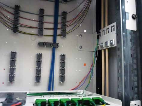
3.5. Kit anneaux à volet
Shutter rings kit
Pour gérer les tubes entre les dispositifs To manage the tubes between the clamping
d’arrimage et d’épanouissement et les and fanout devices and the modules.
modules.
Fixation horizontale ou verticale. Horizontal or vertical fastening.
Kit anneaux à volet
Shutter rings kit
ABS1513/A 17/24OPTEASTAR 2+
3.6. Chemin de câbles horizontal 2U 19’’
2U 19’’ horizontal cableway
Placement possible Position at the top or
en haut ou en bas at the bottom of the
des montants 19’’ 19 ‘’ uprights or at the
ou au centre, selon centre, depending on
le besoin. requirements.
x4
19’’ (2 U): E=76mm
E
x4
Kit chemin de câbles horizontal 2U 19’’
2U 19’’ horizontal cableway kit
x4
x2
ABS1513/A 18/24OPTEASTAR 2+
3.7. Kits toits
Roof kits
x2
x2
Même procédure à droite
Same procedure at the right
/ 900X300 En haut
At the top
/
800X300
/
600X300
/
300X300
+
x4
En bas
At the bottom
Kit toit plein/à brosse et ses accessoires
Full roof/roof with brush kit with accessories
Dévisser
x4
Unscrew x2
Même procédure
à droite
Same procedure Fig. Vue de dessous
at the right Bottom view
ABS1513/A 19/24OPTEASTAR 2+
4. MISE EN PLACE DES CÂBLES
CABLES INSTALLATION
Pour plus de détails, se reporter aux instructions For more information, refer to the instructions
fournies avec les B.A.E.P. provided with the P.F.C.B.
Toujours commencer
le câblage du
côté opposé à la
1 2
charnière (à gauche
dans l’exemple ci-
contre).
Câbler d’abord
MEB 144
le module le plus
éloigné.
Always start cabling
MEB 144 on the side opposite
to that of the hinge
(on the left in this
MEB 144
example).
Proceed first with the
furthest module.
MEB 144
MEC 24
MEC 24
MEC 24
MEC 24
MEC 24
MEC 24
ABS1513/A 20/24OPTEASTAR 2+
5. SCHÉMAS DE BRASSAGE
PATCHING SCHEMATICS
Les tambours de lovage peuvent être The coiling drums can be moved
déplacés selon les besoins. according to needs.
5.1. Baie seule
Single cabinet
La longueur de cordons
préconisée est 2,5 m.
The recommended
patchcords length is 2.5m.
ZONE 1
ZONE 2
Fig. Baie 900x300 - Rack à gauche
900x300 cabinet - Left rack
ABS1513/A 21/24OPTEASTAR 2+
5.2. Baies dos-à-dos
Back-to-back cabinets
La longueur de
cordons préconisée
est 5,5 m.
The recommended
patchcords length is Passage central
5.5m. Central pathway
Baie avant Baie arrière
Front cabinet Rear cabinet
ZONE 1 ZONE 1
ZONE 2 ZONE 2
Fig. Baies 900x300 - Rack à gauche, passage central des cordons
900x300 cabinets - Left rack, central cable pathway
ABS1513/A 22/24OPTEASTAR 2+ ABS1513/A 23/24
OPTEASTAR 2+

                            NEXANS INTERFACE
     25, avenue Jean Jaurès - BP 11 - 08330 - Vrigne-aux-Bois - FRANCE
       Téléphone :+33 (0) 3.24.52.61.61 Fax : +33 (0) 3.24.52.61.66
   Tous les schémas, dessins, spécifications, plans et détails de poids, tailles et dimensions figurant dans la
   documentation technique ou commerciale de Nexans ont un caractère purement indicatif et ne sauraient
           engager Nexans ou être traités comme constitutifs d’une garantie de la part de Nexans.
  All drawings, designs, specifications, plans and particulars of weights, size and dimensions contained in the
 technical or commercial documentation of Nexans is indicative only and shall not be binding on Nexans or be
                         treated as constituting a representation on the part of Nexans.

ABS1513/A                                                                                                   24/24
Vous pouvez aussi lire