OS2 Hardware User Manual - Ouster For Rev 06 OS2 Sensors
←
→
Transcription du contenu de la page
Si votre navigateur ne rend pas la page correctement, lisez s'il vous plaît le contenu de la page ci-dessous

OS2 Hardware User Manual
             For Rev 06 OS2 Sensors

                           Ouster

                         Jul 25, 2022
Contents
1   Important Safety Information                                                                                   3
    1.1 Safety & Legal Notices . . . . . . . . . . . . . . . . . . . . . . . . . . . . . . . . . . . . . . . .     3
    1.2 Proper Assembly, Maintenance and Safe Use . . . . . . . . . . . . . . . . . . . . . . . . . .              6
    1.3 Sensor Cleaning . . . . . . . . . . . . . . . . . . . . . . . . . . . . . . . . . . . . . . . . . . . .    7

2 Sensor                                                                                                          8
  2.1 Overview . . . . . . . . . . . . . . . . . . . . . . . . . . . . . . . . . . . . . . . . . . . . . . . .    8
  2.2 OS2 Product Models . . . . . . . . . . . . . . . . . . . . . . . . . . . . . . . . . . . . . . . . .        9

3 Mechanical Interface                                                                                       9
  3.1 Included Components . . . . . . . . . . . . . . . . . . . . . . . . . . . . . . . . . . . . . . . . 9
  3.2 Mounting Guidelines . . . . . . . . . . . . . . . . . . . . . . . . . . . . . . . . . . . . . . . . . 10
  3.3 Operating Temperatures . . . . . . . . . . . . . . . . . . . . . . . . . . . . . . . . . . . . . . . 11

4 Electrical Interface                                                                                   11
  4.1 Power Supply and Operating Voltage . . . . . . . . . . . . . . . . . . . . . . . . . . . . . . . 11
  4.2 Connection through the Interface Box . . . . . . . . . . . . . . . . . . . . . . . . . . . . . . . 11
  4.3 Direct Cable Connection and Pinout . . . . . . . . . . . . . . . . . . . . . . . . . . . . . . . . 12

5 Digital IO                                                                                              13
  5.1 SYNC_PULSE_IN . . . . . . . . . . . . . . . . . . . . . . . . . . . . . . . . . . . . . . . . . . . 13
  5.2 MULTIPURPOSE_IO (M_IO) . . . . . . . . . . . . . . . . . . . . . . . . . . . . . . . . . . . . . 15

6 OS2 CAD files                                                                                                   15

7 Accessories                                                                                                  16
  7.1 Cables . . . . . . . . . . . . . . . . . . . . . . . . . . . . . . . . . . . . . . . . . . . . . . . . . 16
  7.2 Interfaces . . . . . . . . . . . . . . . . . . . . . . . . . . . . . . . . . . . . . . . . . . . . . . . 18

8 GPS/GNSS Synchronization Guide                                                                          26
  8.1 Setting up your GPS/GNSS . . . . . . . . . . . . . . . . . . . . . . . . . . . . . . . . . . . . . 26
  8.2 Connecting the Hardware . . . . . . . . . . . . . . . . . . . . . . . . . . . . . . . . . . . . . . 26
  8.3 Configuring the Ouster Sensor . . . . . . . . . . . . . . . . . . . . . . . . . . . . . . . . . . . 29

9 Support                                                                                                         29

                                                         2
1 Important Safety Information
1.1 Safety & Legal Notices

The OS2-128, OS2-64, and OS2-32 have been evaluated to be Class 1 laser products per 60825-1:
2014 (Ed. 3) and operate in the 865nm band.

L’OS2-128, l’OS2-64, et l’OS2-32 répondent aux critères des produits laser de classe 1, selon la norme
IEC 60825-1: 2014 (3ème édition) et émettent dans le domaine de l’infrarouge, à une longueur d’onde
de 865nm environ.

FDA 21CFR1040 Notice: OS2-128, OS2-64, and OS2-32 comply with FDA performance standards for
laser products except for deviations pursuant to Laser Notice No. 56, dated January 19, 2018.

Notice FDA 21CFR1040: L’OS2-128, l’OS2-64, et l’OS2-32 sont conformes aux exigences de perfor-
mances établies par la FDA pour les produits laser, à l’exception des écarts en application de l’avis
nº56, daté du 19 janvier 2018.

                                    Figure 1.1: Class 1 Laser Product

                                   Figure 1.2: Caution “Sharp Edges”

The following symbols appear on the product label and in the user manual have the following meaning.

CAUTIONS:

                                                   3
Figure 1.3: This symbol indicates that the sensor emits laser radiation.

    Figure 1.4: This symbol indicates the presence of a hot surface that may cause skin burn.

The OS2 is a hermetically sealed unit, and is non user-serviceable.

Use of controls, or adjustments, or performance of procedures other than those specified herein,
may result in hazardous radiation exposure.

Use of the OS2 is subject to the Terms of Sale that you agreed and signed with Ouster or your
distributor/integrator. Included in these terms are the prohibitions of:

    Removing or otherwise opening the sensor housing

    Inspecting the internals of the sensor

    Reverse-engineering any part of the sensor

    Permitting any third party to do any of the foregoing

Operating the sensor without the attached mount that is shipped with the sensor, or attaching
the sensor to a surface of inappropriate thermal capacity runs the risk of having the sensor
overheat under certain circumstances.

This lidar sensor features a modular cap design to enable more flexible mounting and integration
solutions for the sensor.

The modular cap design increases design flexibility but it does not remove the need for ther-
mal management on top of the sensor. The attached radial cap serves an important thermal
management purpose and the sensor will not operate properly without a cap.

Operation for extended periods of time without the cap will result in system errors and the sen-
sor overheating. The cap can be replaced with alternative solutions but it cannot be left off
altogether.

If you wish to operate the sensor with a custom mounting solution, please contact our Field Ap-
plication Team and we can answer your questions and provide guidance for achieving proper
operations.

This product emits Class 1 invisible laser radiation. The entire window is considered to be the
laser aperture. While Class 1 lasers are considered to be “eye safe”, avoid prolonged direct view-

                                                4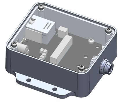
ing of the laser and do not use optical instruments to view the laser.

   When operated in an ambient temperature >40�°C, the metallic surfaces of the sensor may be
   hot enough to potentially cause skin burn. Avoid skin contact with the sensor’s base, lid and
   the heatsink when the sensor is operated under these conditions. The sensor should not be
   used in an ambient temperature above 60°C. The maximum safety certified ambient operating
   temperature is 60°C.

PRECAUTIONS:

   L’OS2 est une unité hermétiquement scellée, qui ne peut être entretenue ou modifiée par
   l’utilisateur.

   L’utilisation de commandes, de réglages, ou l’exécution de procédures autres que celles spéci-
   fiées dans le présent document peuvent entraîner des rayonnements laser dangereux.

   L’utilisation de l’OS2 est soumise aux conditions de vente signées avec Ouster ou le distribu-
   teur/intégrateur, incluant l’interdiction de:

       Retirer ou ouvrir de quelque façon le boîtier du capteur

       Analyser les composants internes du capteur

       Pratiquer la rétro-ingénierie de toute ou partie du capteur

       Autoriser une tierce personne à mener les actions listées ci-dessus

   L’utilisation du capteur sans le support (fourni avec les capteur) ou sans contact avec une sur-
   face ayant des capacités thermiques adéquates peut entraîner une surchauffe du capteur dans
   certaines conditions.

   Ce capteur présente une conception avec un dissipateur thermique supérieur modulaire, ceci
   pour apporter plus de flexibilité de montage et d’intégration au capteur.

   Cette conception modulaire augmente la flexibilité de conception mais ne supprime pas le be-
   soin de dissipation thermique au-dessus du capteur. Le dissipateur thermique radial fourni est
   essentiel à une bonne gestion thermique. Le capteur ne fonctionnera pas correctement sans
   cette pièce.

   Une utilisation prolongée du capteur sans le dissipateur thermique supérieur peut résulter à des
   erreurs système ainsi qu’à une surchauffe du capteur pouvant aller jusqu’à son extinction. Le
   dissipateur thermique fourni peut être remplacé par une autre solution de dissipation thermique
   adéquate, mais ne doit pas être simplement retiré.

   Si vous souhaitez utiliser votre capteur avec une dissipation thermique personnalisée, merci de
   contacter notre Équipe Support qui pourra répondre à vos questions et vous apporter le support
   et le conseil nécessaire.

   Ce produit émet un rayonnement laser invisible de classe 1. L’ouverture de sortie du laser est
   constituée par la fenêtre du capteur dans sa totalité. Même si les lasers de classe 1 ne sont pas
   considérés comme dangereux pour les yeux, ne regardez pas directement le rayonnement laser
   de façon prolongée et n’utilisez pas d’instruments optiques pour observer le rayonnement laser.

   Lors d’une utilisation à température ambiante supérieure à 40°C, la surface métallique du cap-

                                                5
teur peut présenter des risques de brûlures pour la peau. Dans ces conditions, il est important
     d’éviter tout contact avec la partie supérieure, la base ou le dissipateur thermique du capteur.
     Le capteur ne doit pas être utilisé à une température ambiante supérieure à 60˚C. 60˚C est la
     température maximale certifiée d’opération sûre du capteur.

Equipment Label: Includes model and serial number and a notice that states the unit is a Class 1 Laser
Product, is affixed to the underside of the Sensor Enclosure Base. It is only visible after the attached
mount with which the Sensor is shipped, is removed. For location details please refer to figure Sensor
Components in the Mechanical Interface Section.

L’étiquette de l’équipement, comprenant le modèle, le numéro de série, et la classification du produit
laser (ici, classe 1), est apposée au-dessous de la base du boîtier du capteur. Il n’est visible qu’après
avoir retiré le diffuseur de chaleur avec lequel le capteur est expédié. L’emplacement est décrit avec
précision dans la section Sensor Components.

Electromagnetic Compatibility: The OS2 is an FCC 47 CfR 15 Subpart B device. This device complies
with part 15 of the FCC Rules. Operation is subject to the following conditions: (1) This device may
not cause harmful interference, and (2) this device must accept any interference received, including
interference that may cause undesired operation.

“Ouster” and “OS2” are both registered trademarks of Ouster, Inc. They may not be used without
express permission from Ouster, Inc.

If you have any questions about the above points, contact us at legal@ouster.io.

1.2 Proper Assembly, Maintenance and Safe Use

The OS2 can be easily set up by following the instructions outlined in Mounting Guidelines. Any mount-
ing orientation is acceptable. Each sensor is shipped with an attached mount that can be used for test
or normal use within the specified operating conditions. The sensor may also be affixed to any other
user specific mount of appropriate thermal capacity. Please contact Ouster for assistance with ap-
proving the use of user specific mounting arrangements.

Any attempt to utilize the sensor outside the environmental parameters delineated in the OS2
datasheet may result in voiding of the warranty.

When power is applied, the sensor powers up and commences boot-up with the laser disabled. The
boot-up sequence is approximately 60s in duration, after which the internal sensor optics subassem-
bly commences spinning, the laser is activated, and the unit operates in the default 1024 x 10 Hz mode.
When the sensor is running, and the laser is operating, a faint red flickering light may be seen behind
the optical window.

Note that the OS2 utilizes an 865nm infrared laser that is only dimly discernible to the naked eye. The
sensor is fully Class 1 eye safe, though Ouster strongly recommends against peering into the optical
window at close range while the sensor is operating. Ouster sensors are equipped with a multi-layer
series of internal safety interlocks to ensure compliance to Class 1 Laser Eye Safe limits.

The OS2 is a hermetically sealed unit, and is not user-serviceable. Any attempt to unseal the enclosure
has the potential to expose the operator to hazardous laser radiation.

The sensor user interface may be used to configure the sensor to a number of combinations of scan

                                                   6
rates and resolutions other than the default values of 1024 x 10 Hz resolution. In all available combi-
nations, the unit has been evaluated by an NRTL to remain within the classification of a Class 1 Laser
Device as per IEC 60825-1:2014 (Ed. 3).

Assemblage correct et utilisation sûre

L’OS2 s’installe facilement en fixant la base sur un support percé de trous concordants, et en suivant
les instructions d’interconnexion décrites dans la section Mounting Guidelines. Toute orientation de
montage est acceptable. Chaque capteur est expédié équipé d’un dissipateur de chaleur, utilisable
en phase de test et en conditions normales. Néanmoins tout autre support présentant une capacité
thermique appropriée pour l’application de l’utilisateur peut être utilisé. Veuillez contacter Ouster dans
le cas où un montage spécifique à votre application serait nécessaire.

Toute tentative d’utilisation du capteur en dehors des paramètres environnementaux définis dans la
fiche technique de l’OS2 peut entraîner l’annulation de la garantie.

Lorsque le capteur est sous tension, celui-ci démarre et commence son initialisation avec le laser dés-
activé. Le temps de démarrage est d’environ 60s, après quoi le sous-système optique entre en rotation
et le laser est activé, le capteur opère alors dans son mode par défaut de 1024 x 10 Hz. Lorsque le cap-
teur est en marche et que le laser est activé, on peut apercevoir une faible lumière rouge vacillante
derrière la vitre teintée. L’OS2 utilise une longueur d’ondes infra-rouge de 865nm nm à peine percep-
tible pour l’œil humain, et le rayonnement laser IR émis est sans danger pour les yeux. Cependant,
bien que les rayonnements laser de classe 1 soient sans danger dans des conditions raisonnablement
prévisibles, Ouster recommande fortement de ne pas regarder fixement la vitre teintée pendant que le
capteur est en marche. L’OS2 est une unité hermétiquement scellée, qui ne peut pas être entretenue,
modifiée ou réparée par l’utilisateur. Toute tentative d’ouverture du boîtier a pour risque d’exposer
l’opérateur à un rayonnement laser dangereux.

L’OS2 est une unité hermétiquement scellée, qui ne peut pas être entretenue, modifiée ou réparée.
Toute tentative d’ouverture du boîtier a pour risque d’exposer l’opérateur à un rayonnement laser dan-
gereux.

Les capteurs Ouster sont équipés d’une série de dispositifs de sécurité à plusieurs niveaux, de façon à
assurer en toutes circonstances le respect des limites d’irradiance correspondant aux rayonnements
lasers de classe 1, sans danger pour les yeux.

L’interface utilisateur du logiciel du capteur peut être utilisée pour configurer le capteur selon un cer-
tain nombre de combinaisons de vitesses de balayage et de résolutions autres que les valeurs utilisées
par défaut, respectivement de 1024 x 10 Hz.

1.3 Sensor Cleaning

All Ouster Sensor window are made from polycarbonate. Based on the sensor usage you may see dust,
bugs and/or layers of mud/debris on the window. Before you attempt to clean your sensor, please read
the instructions below on best practices for cleaning Ouster Sensors.

Required Materials:

     Few clean microfiber cloths

                                                    7
Warm water
Mild liquid dishwashing soap
Spray bottle with clean water
Spray bottle with mild soapy water
99% Isopropyl alcohol
Warning:
Avoid getting water into the power connector.
Avoid using hard water when cleaning the sensor.
Do not use acetone to clean the window. It will embrittle the polycarbonate.
Do not wipe dirt directly from the sensor. Spray it off with warm water first.
Procedure:
Using the 99% isopropyl alcohol and a clean microfiber towel, wipe away bugs/mud/debris from
the sensor.
Spray the sensor with warm, mild-soapy water and gently wipe the sensor with a clean microfiber
towel. Wipe along the curve of the sensor, not top-to-bottom (think moving with the grain).
Spray the sensor with clean water to rinse off the soap and dry with a second microfiber towel.
Enjoy your clean window.
2 Sensor
2.1 Overview
The OS2 offers an industry-leading combination of price, performance, reliability, size, weight, and
power. It is designed for indoor/outdoor all-weather environments and a long operating lifetime.
The OS2 family of sensors consist of three models, the OS2-128, OS2-64, and OS2-32, with differing
vertical resolution, but identical mechanical dimensions.
For the purposes of this document, the term “OS2” refers to the family of sensors, and only where
there is a difference in performance will each model be referred to by its specific model designation.
The contents of this manual are applicable only to Rev 06 sensors. Please contact support@ouster.io
with the sensor serial number to find out your sensor Rev information. For all other sensor hardware
revisions, please refer to the respective hardware user manual found here Here.
82.2 OS2 Product Models
The OS2 is available with 128, 64, or 32 beams of vertical resolution and with Uniform, Gradient, Above
Horizon, or Below Horizon beam spacing options. Product specs and more information on these con-
figurations can be found on the OS2 product page.
3 Mechanical Interface
3.1 Included Components
The OS2 is shipped with the following items:
OS2-128, OS2-64, or OS2-32
Sensor to interface box cable/connector
Interface Box and 24V AC/DC power supply (2 meters)
RJ45 cable (1 meter)
Baseplate Mount
Figure 3.1: Sensor Components
Downloadable CAD files for the OS2 can be found online at Ouster Download Page
9Warning: The water ingress protection rating for the sensor is only valid if the I/O cable is plugged
into the panel mount connector on the base of the sensor, and the locking collet rotated past the
détente click to the properly locked condition i.e past the détente position. The cable and plug
are an element of the sensor ingress protection system. Without the connected cable the ingress
protection rating may be compromised. Bending the cable at a sharp angle directly after egress
from the plug over mold should also be avoided. Sharp bends and high axial stresses on the cable
immediately adjacent to the plug over mold may create a moisture ingress path into the connector.
Please note the cable minimum bend radius requirements below:
3.2 Mounting Guidelines
Our sensors ship with modular mounting options. The sensor can be mounted in any orientation.
Proper mounting will ensure optimal sensor performance, reducing noise from vibration and providing
efficient heat dissipation.
Mount to a material with high thermal conductivity. The following are recommended aluminum
alloys and their thermal conductivity:
1) 6061: 167 W/m-K
2) 7075: 130 W/m-K
3) 2024: 121 W/m-K
Ensure interfaces are clean and free from debris.
M3 screws are recommended for mounting the sensor. The screw hole pattern in presented in
the Sensor drawing above Sensor Components.
Torque bolts appropriately for the mount material and bolts. A torque of 146cNm is recom-
mended for a2 stainless steel screws.
Use TIM (Thermal Interface Material) for any irregular or unmachined surfaces.
Do not overconstrain the sensor if mounting to both the top and the bottom.
Use a thermally conductive pad to ensure good conductivity while not over constraining.
Ensure your implementation maintains the base and top of the sensor at no greater than 25ºC
above ambient with an ambient less than 50ºC.
The shape of any heatsink should maximize the surface area for free and forced convection while
being thick enough to allow the heat to conduct through the material.
If you have questions about your specific mounting situation please contact the Ouster at sup-
port@ouster.io.
103.3 Operating Temperatures
Thermal requirements specific to Rev 06 are listed below. The sensor has three operating states in
order to manage high temperatures: Active, Shot Limiting, or Inactive. In the standard Active state
the sensor will perform to the range and precision specifications of the datasheet. When the sensor
reaches a certain temperature (see table below for reference), it enters Shot Limiting state and issues
an alert. In Shot Limiting state, the sensor reduces power to the lasers in order to reduce the thermal
load. While in this state, sensor range and precision may degrade by up to 20%. When the sensor
reaches the maximum operating temperature specified below, the sensor may become Inactive and
shut off.
Please contact support@ouster.io with your sensor serial number to find out your sensor revision.
Table 3.1: Maximum thermal performance for Rev 06 OS2 Sensor
Convective Air Temp with Radial
Heatsink and Standard Base
Max temp before shot limiting 55ºC
Temp that shot limiting saturated (sensor may turn 61ºC
off above this temperature)
4 Electrical Interface
4.1 Power Supply and Operating Voltage
The OS2 Rev 06 Sensors are meant to operate at 12V and 24V nominal input voltage. A low voltage
warning will be triggered if the voltage at the sensor connector drops below 9.5V. The sensor will shut
down if this input voltage drops to 9V. The maximum input voltage is 34V for the OS2 sensor. When
used without the provided interface box, ensure that the power supply is compliant with the operating
voltage specified above and allows to supply at least 20 W.
4.2 Connection through the Interface Box
The Interface Box that accompanies the OS2 is designed to allow the sensor to be operated for test
and evaluation purposes in indoor environments only. It can be connected to the sensor with a cable
equipped with connectors on both ends. It allows the sensor to be powered up and provides access
to the sensor gigabit Ethernet Interface via a standard RJ45 connector. DC Power to the sensor is
provided to the Interface Box by the accompanying 24V DC power supply.
114.3 Direct Cable Connection and Pinout
The OS2 can be operated without the use of an Interface Box. In this case, a “pigtail” cable should
be used and wires should be connected by the user following the Pinout presented below. When used
with direct cable connection, the sensor should still be operated within the operating voltage specified
in section Power Supply and Operating Voltage
Warning: Ouster is not responsible for any errors in wiring as a result of bypassing the Interface
Box and this activity may result in a voiding your warranty if it results in damage to the sensor.
The following guidelines for direct cable connection assume use of the Ouster-provided 24V 1.5A
power supply. Ouster cannot be held responsible for damage to the device if alternate is used.
Figure 4.1: Cable pinout of on-sensor receptacle
Table4.1: Cable pinout wires
Net Name Pin Wire Color Wire Wire Wire Twisted
Number AWG AWG AWG With
(Type-1, (Type-2, (Type-3,
24V) 24V) 12V)
MULTIPUR- 3 Purple 26 AWG 28 AWG 28 AWG N/A
POSE_IO
SYNC_PULSE_IN 2 Yellow 26 AWG 28 AWG 28 AWG N/A
VCC 1 Red 22 AWG 22 AWG 18 AWG N/A
GROUND 7 Black 22 AWG 22 AWG 18 AWG N/A
TRP_1_P (Ether- 5 White/Or- 26 AWG 28 AWG 28 AWG Orange
net) ange
TRP_1_N (Ether- 4 Orange 26 AWG 28 AWG 28 AWG White/Or-
net) ange
continues on next page
12Table 4.1 – continued from previous page
Net Name Pin Wire Color Wire Wire Wire Twisted
Number AWG AWG AWG With
(Type-1, (Type-2, (Type-3,
24V) 24V) 12V)
TRP_2_P (Ether- 8 White/- 26 AWG 28 AWG 28 AWG Green
net) Green
TRP_2_N (Ether- 6 Green 26 AWG 28 AWG 28 AWG White/-
net) Green
TRP_3_P (Ether- 9 Blue 26 AWG 28 AWG 28 AWG White/Blue
net)
TRP_3_N (Ether- 10 White/Blue 26 AWG 28 AWG 28 AWG Blue
net)
TRP_4_P (Ether- 12 White/Brown 26 AWG 28 AWG 28 AWG Brown
net)
TRP_4_N (Ether- 11 Brown 26 AWG 28 AWG 28 AWG White/Brown
net)
5 Digital IO
5.1 SYNC_PULSE_IN
SYNC_PULSE_IN is a dedicated input channel that is accessible within the Interface Box Jumper J4. This
channel expects an input pulse sequence which can be used for time synchronization. Refer to the
Software User Manual for more information on configuring this input. Any references to pulse polar-
ity in this document references the signal polarity on the SYNC_PULSE_IN pin of the sensor. This input
channel is protected by an opto-isolator which will draw 5mA at full operation.
Table5.1: SYNC_PULSE_IN Interface Requirements
Parameter Min Voltage Max Voltage Min Driver Current
LOGIC LOW -30 V 2V N/A
LOGIC HIGH 2.9 V 30 V 3mA @3.3V~5V, 5mA
at 24V and higher
SYNC_PULSE_IN Interface requirements were tested with 2 m cable Interface Box connection at 2
MHz.
When GPIO has 5 mA drive strength minimum, GPIO can be directly connected to the
SYNC_PULSE_IN pin of the Interface Box header. This is the most common case and has been tested
13to work on common Arduino microcontroller series. Typical common logic levels of 3.3 V, 5 V
GPIO of microcontrollers can produce drive strength of 5 mA min (Arduino, MSP430, etc.).
Figure 5.1: Example Circuits for 3.3 V and 5 V logic
If the 5 mA drive strength minimum cannot be met, a buffer circuit is required to drive
SYNC_PULSE_IN. Example circuits are provided for common 3.3 V and 5 V logic.
Figure 5.2: Example Circuits for 3.3 V and 5 V logic
145.2 MULTIPURPOSE_IO (M_IO)
MULTIPURPOSE_IO (M_IO) is a configurable input or output channel accessible within the Interface Box
Jumper J4 connected to the MULTIPURPOSE_IO pin of the Interface Box. Detailed information on how
to configure this channel using the sensor TCP interface can be found in the API Guide. By default this
channel is disabled.
When this channel is configured as an OUTPUT, the M_IO sends a pulse sequence that can be used for
time synchronization or event triggering outside the sensor. For a full description of output pulse trig-
gering options, refer to the Software User Manual for more information. This output is an opto-isolated
open collector circuit, relying on an externally provided pull-up resistor. This resistor is provided for a
typical 3.3V/5V application as part of the Interface Box circuitry.
Table5.2: MULTIPURPOSE_IO - OUTPUT Interface Requirements
Parameter Min Max
Pull Up Voltage 3.3 V 24 V
Sinking Current N/A 25 mA
When this channel is configured as an INPUT, the M_IO can accept a standard NMEA $GPRMC UART
message. These messages are a common way for GPS systems to share timestamp information in
UTC time format. More information on this packet structure and supported baud rates can be found
in the Time Synchronization section of the Software User Manual.
Table5.3: MULTIPURPOSE_IO - INPUT Interface Requirements
Parameter Min Voltage Max Voltage Min Driver Current
LOGIC LOW -30 V 2V N/A
LOGIC HIGH 2.9 V 30 V 3mA @3.3V~5V, 5mA
at 24V and higher
Above are tested with 35m (200uH inductance) cable Interface Box connection at 115200 Baudrate.
6 OS2 CAD files
The most up-to-date CAD files of all our products can be found on our Lidar Product Details page.
157 Accessories
7.1 Cables
Cable Types
3 types of cables are compatible with the OS2 sensors. Their physical characteristics are presented
in the table Cable Characteristics.
The cable and plug are an element of the sensor ingress protection. Without this, the ingress protec-
tion rating may be compromised. Bending the cable at a sharp angle directly after egress from the
plug over mold should also be avoided. Sharp bends and high axial stresses on the cable immediately
adjacent to the plug over mold may create a moisture ingress path into the connection. Please note
the cable minimum bend radius requirements.
Note: We no longer offer Type 1 cables for sale. Please contact your Ouster sales representative for
questions regarding available cable lengths, connector types, and termination options.
Table 7.1: Cable Characteristics
Cable Outer Diame- Cable Minimum Bend Cable Minimum Bend (Flexi-
ter (Static) ble)
Type 1 10.5mm 79mm 158mm
(Thick)
Type 2 (Thin) 8mm 40mm 80mm
Type 3 8.2mm 41mm 82mm
Note: Type 3 Cable has an imprint that states “Type 3” on it whereas, Type 2 does not have any
identifiers.
Note: Ouster recommends using a right angled connector cable for use cases wherein the cable
needs to be bent within the first 5 cm between the connector and the rest of the cable.
16Electrical Characteristics
Ouster has characterized the cable resistance and contact resistance of our cables at room temper-
ature. This can be found below:
Table 7.2: Electrical Characteristics
Cable Maximum Cable Re- Typical End to End Resis- Admissible Nominal Oper-
sistance (Ω/m) tance for 5m Cable (Ω) ating voltage (V)
Type 1 0.110 0.45 24
(Thick)
Type 2 0.110 0.45 24
(Thin)
Type 3 0.042 0.3 12 / 24
For full sensor functionality, a minimum of 9.5 V must reach the sensor. To compensate for losses
through wire resistance, a higher voltage must be provided to the interface end of the cable, which
may be the Interface Box or the pigtail wires. If the sensor is below this voltage for at least 1 second,
the INPUT_VOLTAGE_LOW error will be triggered.
The following graph can be used as a guide to determine the appropriate input voltage to the sensor
connector for your desired cable length. The values on the graph were calculated using idealized cable
resistances derived from the AWG system and assumed maximum power draw from the sensor.
177.2 Interfaces
All Interface Boxes are provided with a DC power port and an 8-pin modular jack for Ethernet. Currently
Ouster offers two types of Interface boxes to support both 12V and 24V.
Interface Boxes (Standard) provided with Type 1 and Type 2 cables are assembled with integral cables
for connection to Ouster’s sensors. This cable cannot be disconnected from the interface box, as there
is no connector available.
The Interface Boxes (12V Compatible) with Type 3 cables are provided with an output connector and
a separate connectorized cable for connection to Ouster’s sensors. These Interface Boxes also have
a new GPS input connector capable of accepting operating TTL levels originating in a separate GPS
device containing static electricity dissipation circuitry.
Example: GPS Module compatible with Ouster Sensor GPS Module.
Note: If you need support to configure the GPS to works with our sensor please contact sup-
port@ouster.io.
Warning: RISK OF FIRE OR ELECTRIC SHOCK. DO NOT CONNECT THE GPS CONNECTOR DI-
RECTLY TO AN ANTENNA.
7.2.1 Interface Box 24V Compatibility (Standard)
The Interface Box that accompanies the OS2 is designed to allow the sensor to be operated for test
and evaluation purposes. It terminates the interface cable from the sensor, allows it to be powered
up and provides access to the sensor gigabit Ethernet Interface via a standard RJ45 connector. DC
Power to the sensor is provided to the Interface Box by the accompanying 24V DC Supply.
Note: The Ouster Interface Box is a support tool for use in laboratory environments to assist cus-
tomers in evaluating Ouster’s LiDAR sensor products and in the development of software. The In-
terface Box is not protected from ingress of moisture or solid particles and is not intended for use
outdoors.
18Cable Connection and Pinout
The OS2 can be operated without the use of an Interface Box. For more information on the Ouster
Cable Pinout please refer to Direct Cable Connection and Pinout
197.2.2 Interface Box 12V (Compatible)
This type of interface box is engineered for users who require the use of 12V DC power supply. These
interface Boxes also have a new GPS input connector capable of accepting operating TTL levels that
originate in a separate GPS device containing a static electric dissipation circuit.
Figure 7.1: Interface Box -12V compatibility
Interface Box Specification
1 - This feature is optional for Rev 06 Sensor and above and is compatible with Type 3 Cables
only. Standard Interface box without this connector is also available and is provided with Type 1
and Type 2 cables for connection to Ouster’s sensor.
2 - Ethernet jack. RJ45, gigabit speed (1000base-T).
3 - VIN Barrel Jack. Use with a 2.5mm inner diameter, 5.5mm outer diameter barrel plug.
4 - User replaceable 5A fuse. Use only Littlefuse #0891005.
5 - VIN green LED indicator (D2), fuse-protected VIN header (J10) and Ground header / jumper
storage (J14).
6 - Onboard MAXM15067 buck powering VCC_3P3|5. VCC_3P3|5 supplies the onboard LEDs and
pullups, and is user accessible via headers J2 & J7. Header J5 is used to select the buck’s output
voltage: install a jumper for 3.3V, leave open for 5V. WARNINGS: Max allowable user consumption
is 210mA. Ensure power to the Interface Box is disconnected when changing buck output voltage
via J5.
20Figure 7.2: Components
7 - 3.3kΩ pullups to VCC_3P3|5 and green LED indicators for MULTIPURPOSE_IO and
SYNC_PULSE_IN. Install a jumper on the respective header (J8 or J9) to enable the pullup.
Figure 7.3: J8 & J9 Circuitry
8 - 0.1” pitch, 4x2 pin header J7. GPS_TX (Pin 1) is only connected to connector J2; it is not
connected to the sensor.
9 - 6-pin JST SH/SR connector J2. VCC_J2 (Pin 2) is connected to VCC_3P3|5 by installing a
jumper on header J6. GPS_TX (Pin 6) is only connected to header J7; it is not connected to the
sensor.
21Figure 7.4: J7 Circuitry
Figure 7.5: J2 Circuitry
22Connectors
Connectivity Guide:
RJ45: Ethernet connection to a computer
6-PIN JST SH/SR: GPS connector port
Barrel Jack: 24V DC power supply
Figure 7.6: Connector Outline
Electrical Characteristics
The Type 1 and Type 2 cable Interface Boxes are rated 24 Vdc, 1.1 A and supports all Ouster sensors.
The Type 3 cable Interface Box is rated 12 Vdc, 3.3 A and 24 Vdc, 1.1 A. This Interface Box supports
24V operation on all Ouster sensors, and 12V operation for Rev 05 and above sensors only.
23Overcurrent Protection
Type 1 and Type 2 cable Interface Boxes Interface Boxes are provided with thermistor type overcurrent
protection to supplement the internal overcurrent protection in the sensor. The thermistor is soldered
in place and is not user replaceable.
The Type 3 Interface Box contains a user replaceable 5A mini blade fuse. When replacing this fuse,
use only a Littelfuse - Type 891005 fuse. Use of any other fuse may lead to a risk of fire.
Power Supply
The Interface Box ships with a 24 Vdc power supply and a cordset suitable for use in the U.S and
Canada. Type 1 and Type 2 Interface Boxes are only designed for use with this 24 Vdc power supply
and the Type 3 Interface Boxes are designed to operate from a 12 Vdc source, but a 12 Vdc power
supply is not provided by Ouster.
To select a power supply, it should:
Have a 12 Vdc output voltage rating.
Be capable of delivering at least 3.3A.
Be identified or marked as having a Limited Power Source (LPS) output.
Be safety certified by an acceptable test house in the local region of use using either IEC 60950-1
or IEC 62368-1 (or the EN or other national equivalent).
Be provided with a power supply cordset appropriate for the power supply’s input and the socket
outlets available in the lab space.
Be provided with a 5.5 mm OD barrel type output connector suitable ID for a 2.5 mm OD inner
pin.
24Selecting a Power Supply Cord/Cordset
If purchasing a power supply locally, it should be supplied with an appropriate power supply cord or
cordset for use with the power supply. If it’s necessary to select a power supply cordset for the Ouster
supplied power supply, it should be safety certified by a test house acceptable to the local region of
use, supplied with an IEC 60320, Type C6 cord connector to mate with the power supply and a plug
for connection to an AC outlet with an earthing contact/pin.
Environmental Ratings
All Interface Boxes are suitable for use indoors only in clean, protected environments at temperatures
between -20 °C and +50 °C. Interface Boxes are not designed for use outdoors or in environments
that are not protected from dust, moisture, or high humidity.
Mounting
The interface box may be mounted on a table top or on a wall (or similar vertical surface) not higher
than 2 m above the floor. Use not less than two (2) screws (M4 SHCS 10mm or longer are recom-
mended) to secure the interface box to the mounting surface.
Figure 7.7: Mounting Guidelines -Ibox
For additional OS2 sensor CAD files refer to Lidar Product Details page.
258 GPS/GNSS Synchronization Guide
This guide will explain how to physically connect a GPS to your Ouster sensor and synchronize the
Ouster sensor timestamp to an NMEA sentence.
8.1 Setting up your GPS/GNSS
It is important to ensure you have configured your GPS according to the manufacturer’s specifications.
The Ouster sensor accepts the following:
NMEA sentence type: GPRMC only (future support for other sentence types)
Baud Rates: 9600 or 115200
Polarity: Normal or Reversed (ACTIVE_HIGH 1 or ACTIVE_LOW 2 )
Voltage: 3.3 - 15 V logic with a minimum drive current of 5 mA.
If your GPS can’t meet these minimums you will need to buffer the voltage with an additional
circuit. Details in the Digital IO section of the Ouster Hardware User Manual.
Note: Once you have configured your GPS, it is good practice to verify the signals using an oscil-
loscope. This will ensure you have the correct baud rate, polarity, voltage, and message type being
output.
1 Low to high edge as critical timing event
2 High to low edge as critical timing event
8.2 Connecting the Hardware
The next step to successfully connecting your GPS is ensuring that you have connected the outputs
from your GPS to the correct inputs of the sensor.
For lab applications where you will use the Interface Box, it is recommended to use terminated jumper
wires like these to ensure a solid connection.
26Connection using the GPS Port
Connect the PPS output from your GPS to the sync_pulse_in pin of the GPS connector to be
plugged on the Ouster Interface Box, pictured below in yellow.
Connect the NMEA UART output from your GPS to the multipurpose_io pin of the GPS connector
to be plugged on the Ouster Interface Box, pictured below in magenta.
Connect the ground output from your GPS to the GND pin of the GPS connector to be plugged
on the Ouster Interface Box, pictured below in gray.
Figure 8.1: J2 Circuitry
Connection using the Pin out 4x2 pin header J7
Connect the PPS output from your GPS to the sync_pulse_in pin of the Ouster Interface Box,
pictured below in yellow.
Connect the NMEA UART output from your GPS to the multipurpose_io pin of the Ouster Interface
Box, pictured below in green.
Connect the ground output from your GPS to the GND pin of the Ouster Interface Box, pictured
below in gray.
Table8.1: SYNC_PULSE_IN Interface Requirements
Parameter Min Voltage Max Voltage Min Driver Current
LOGIC LOW -30 V 2V N/A
LOGIC HIGH 2.9 V 30 V 3mA @3.3V~5V, 5mA
at 24V and higher
27Figure 8.2: J7 Circuitry
Figure 8.3: Jumper Wires
28Table8.2: MULTIPURPOSE_IO - INPUT Interface Requirements
Parameter Min Voltage Max Voltage Min Driver Current
LOGIC LOW -30 V 2V N/A
LOGIC HIGH 2.9 V 30 V 3mA @3.3V~5V, 5mA
at 24V and higher
8.3 Configuring the Ouster Sensor
Please refer to the GPS configuration section in the software user manual to configure your sensor to
synchronize its timestamp with the GPS.
9 Support
In case of any questions regarding the contents of this user manual or the configuration of the sensor,
please reach out to support@ouster.io or visit Ouster website.
29Vous pouvez aussi lire