Water Level Alarm 7607/2 - Gebrauchsanleitung Instructions for Use Mode d'emploi - Tunze
←
→
Transcription du contenu de la page
Si votre navigateur ne rend pas la page correctement, lisez s'il vous plaît le contenu de la page ci-dessous
®

Gebrauchsanleitung Water Level Alarm
Instructions for Use 7607/2
   Mode d’emploi                 x7607.2888
                                    02/2015
                                          1
® Inhalt Seite
Allgemeines 4
Lieferform / Funktion 6
Sicherheitshinweise 8
Platzwahl für Steuergerät 7607/2 10
Befestigung 12
7607/2 mit Unterschrankanlagen 14
7607/2 mit Innenfilteranlagen 16
Platzwahl für Sensoren 18-20
Halterung an senkr. Aquarienscheibe 22
Sensorhalterung mit Verlängerung 24
Halterung an waager. Aquarienscheibe 26-28
TUNZE® Aquarientechnik GmbH Halterung an Glasscheibe kleben 30
Leuchtdioden (LED) am Controller 7607/2 32
Seeshaupter Straße 68 Abstecken des Verbindungskabels 34
82377 Penzberg Welche Geräte anschließen? 36
Germany Sensoren 38
Inbetriebnahme bei Unterschrankanlagen 40
Tel: +49 8856 2022 Inbetriebnahme bei Innenfilteranlagen 42
Fax: +49 8856 2021 Funktionstest und Wartung 44
Pflege der Sensoren 46
www.tunze.com Teileliste - Ersatzteile 48
Garantie 50
Email: info@tunze.com Störungen 52-54
Entsorgung 56
2Table of Contents Page Sommaire Page
General aspects 5 Généralités 5
Condition delivered / function 7 Contenu / Fonction 7
Safety instructions 9 Sécurité d’utilisation 9
Location for control unit 7607/2 11 Placement de la commande 7607/2 11
Attachment 13 Fixation 13
7607/2 in aquarium cabinets 15 7607/2 en filtrations sous aquarium 15
7607/2 in internal filter plants 17 7607/2 en filtrations internes 17
Location for sensors 19-21 Placement des capteurs 19-21
Holding device on vertical aquarium pane 23 Fixation sur vitre verticale 23
Sensor holding device with extension 25 Fixation avec prolongateur 25
Holding device on horizontal aquarium pane 27-29 Fixation sur renfort horizontal 27-29
Sticking the holding device on the glass pane 31 Fixation par collage 31
Light-emitting diodes (LEDs) on Controller 7607/2 33 Diodes LED sur Controller 7607/2 33
Disconnecting the connecting cable 35 Déconnexion du câble d’alimentation 35
Which devices can be connected ? 37 Quels appareils peut-on raccorder ? 37
Sensors 39 Capteurs 39
Initial operation in aquarium cabinets 41 Mise en service en filtrations sous aq. 41
Initial operation in internal filter plants 43 Mise en service en filtrations internes 43
Function test and maintenance 45 Test des fonctions et entretien 45
Servicing the sensors 47 Entretien des capteurs 47
List of parts / spare parts 49 Liste des pièces 49
Guarantee 51 Garantie 51
Failures 53-55 Que faire si… ? 53-55
Disposal 56 Gestion des déchets 56
3Allgemeines
Der Water Level Alarm ist ein
Wasserstandsfehlmelder, der als Ergänzung für
Wassernachfüllanlagen dient. Im Störfall werden alle
über die Schaltdose angeschlossenen Verbraucher
abgeschaltet, außerdem ertönt ein Warnsignal und
eine rote Diode leuchtet auf.
(1) Er schützt Filteranlagen im Aquarium oder im
Unterschrank vor Trockenlauf und kann Schäden
vermeiden, die z.B. durch das unbeabsichtigte
Leerpumpen des Filterbehälters entstehen könnten.
Aber auch bei Wasserstandsreglern mit fehlendem
Nachfüllwasser kann der Water Level Alarm vor
Trockenlauf schützen.
(2) In Unterschrankanlagen kann er den
Ablauf überwachen und vor Überlauf des
Aquariums schützen, z.B. beim Verstopfen des
Ablaufrohrsystems.
(3) Der Water Level Alarm kann bestehende
Nachfüllanlagen (Osmolator) mit großem
Wasservorrat überwachen und als Überlaufschutz
arbeiten.
Bitte beachten Sie: Der Water Level Alarm ist kein
Ersatz für Installations- oder Wartungsmängel Ihrer
Anlage.
4General aspects Généralités
The Water Level Alarm is used as a supplement to Water Level Alarm est un indicateur de défaut de
water refilling systems. In the event of a failure, the niveau d’eau complémentaire aux installations de
switched socket outlet switches off all connected régulation de niveau. Lors d’un défaut, tous les
electrical devices; in addition an alarm is sounded appareillages raccordés à la prise commandée se
and a red LED lights up. retrouvent hors service, le défaut est signalé par un
(1) It protects filter systems in the aquarium or in avertisseur sonore et une diode LED rouge.
the cabinet against running dry and can prevent (1) Protège les filtrations internes ou sous aquarium
damage, which might occur by accidental emptying d’un fonctionnement à sec, évite les dommages
of the sump, for example. But, the Water Level aux appareillages pouvant résulter d’un manque
Alarm can also provide protection against running d’eau dans la cuve de filtration. De même et pour
dry for water level regulators lacking refill water. des systèmes de rajout d’eau sans aucune sécurité
(2) In aquarium cabinets, the unit can monitor anti-débordement, l’indicateur défaut de niveau
the outlet and can protect the aquarium against prévient tout disfonctionnement.
overflow when the drain pipe system is clogged, for (2) En filtration sous aquarium, permet une
example. surveillance du déversoir en évitant le débordement
(3) The Water Level Alarm can monitor refilling de l’aquarium lors de l’obstruction de ce déversoir.
systems (Osmolator) with large water store tanks (3) Permet la surveillance du fonctionnement de
and can operate as an overflow protection. l’Osmolator lors de l’utilisation d’une cuve de rajout
Notice: The Water Level Alarm is not a remedy for d’eau de grande capacité, évite le débordement de
defects in installation or maintenance. l’aquarium lors d’un disfonctionnement.
Veuillez observer : Water Level Alarm ne
représente pas la solution à une installation de
mauvaise conception technique ou à un manque de
surveillance.
5Lieferform
Der Water Level Alarm hat 3 Sensoren: Einen
Trockenlaufsensor und 2 Überlaufsensoren. Jeder
Sensor hat einen Halter zum Kleben mit Silikon oder
zum Klemmen an waagerechten oder senkrechten
Scheiben. Die Halter können auch zusammengefügt
werden. Die Steuereinheit hat eine optische
Anzeige für jeden Sensor kombiniert mit Warnton.
Die Schaltsteckdose hat eine Schaltleistung bis zu
230V / 1.800 W (bei 115V / 900 W).
Funktion
Nach richtiger Installation kann der Water
Level Alarm (3) verschiedene Wasserstände
überwachen (1). Über- oder unterschreitet
ein Wasserstand die gesetzten Grenzen,
werden in einem solchen Störfall alle über die
Schaltsteckdose (2) angeschossenen Geräte
abgeschaltet, außerdem ertönt ein Warnsignal
und eine rote Warnlampe (3) leuchtet auf. Nach
der Behebung der Ursache kann am roten Knopf
des Steuergerätes (3) eine Rücksetzung (Reset)
erfolgen. Das Gerät ist wieder betriebsbereit für die
Überwachung. Die Schaltsteckdose führt wieder
Strom.
6Delivery condition Contenu
The Water Level Alarm has three sensors: one run- Water Level Alarm comporte 3 capteurs : un
dry protection sensor and two overflow sensors. capteur contre une marche à sec et 2 capteurs
Each sensor comes with a holding device which can anti-débordement. Chaque capteur possède un
be adhered with silicone or clamped to horizontal support à coller ou à fixer sur une paroi verticale
or vertical panes. The holding devices can also be ou horizontale. Les supports peuvent être reliés
combined. The control unit has an LED indicator for entre eux. La commande électronique intègre une
each sensor combined with an alarm. The switched signalisation optique pour chaque capteur ainsi
socket outlet has a capacity up to 230 V / 1800 W que sonore. La prise commandée est dotée d’un
(at 115 V, 900 W). pouvoir de coupure jusqu’à 230 V / 1.800 W (115 V
/ 900W).
Functions Fonction
After correct installation, the Water Level Alarm (3) Après une installation dans les règles de l’ensemble
can monitor three different water levels (1). If a water du système, Water Level Alarm (3) peut surveiller
level falls short of or exceeds the limits set, all units 3 niveaux d’eau différents (1). Si un des niveaux
connected through a switched socket outlet (2) devait dépasser ou se trouver en-dessous du
are switched off, and in addition a warning signal niveau normal, le défaut généré stoppe tous les
is sounded and a red warning lamp lights up (3). appareillages raccordés à la prise commandée (2).
After removal of the cause, use the red button on Un signal sonore retentit et la diode LED rouge (3)
the control unit (3) for reset. Subsequently, the unit correspondante s’allume. Après élimination du
is ready for monitoring again. The switched socket défaut, une action sur le bouton rouge «Reset» (3)
outlet is energised again. placé sur le Controller efface le défaut. L’appareil
est à nouveau prêt pour la surveillance, la prise
commandée est à nouveau alimentée.
7Sicherheitshinweise
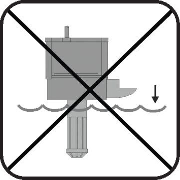
Water Level Alarm nur für Aquarien einsetzen, der
Betrieb im Freien ist nicht zulässig.
Steuergerät 7607/2 nur an trockener und gut
belüfteter Stelle anbringen! (1)
Nicht in die Nähe von Heiz- und Wärmequellen
aufstellen (2), Umgebungstemperatur max. + 35°C.
Magnetscheibenreiniger oder andere Magnete
nicht in die Nähe des Sensors bringen, sonst
Funktionsstörung möglich, mind. 20 cm Abstand
halten (3).
Vor Inbetriebnahme prüfen, ob Betriebsspannung
mit Ihrer Netzspannung übereinstimmt.
Vor Reinigung und Wartung Netzstecker abziehen.
Beschädigte Kabel nicht selbst reparieren, sondern
Geräte zur Reparatur geben.
Water Level Alarm nicht unbeaufsichtigt betreiben.
Dieses Gerät ist für Benutzer (einschl. Kinder)
mit eingeschränkten physischen, sensorischen
oder psychischen Fähigkeiten bzw. ohne jegliche
Erfahrung oder Vorwissen nur dann geeignet,
wenn eine angemessene Aufsicht oder ausführliche
Anleitung zur Benutzung des Geräts durch eine
verantwortliche Person sichergestellt ist. Achten Sie
darauf, dass Kinder nicht mit dem Gerät spielen (4).
8Safety instructions Sécurité d’utilisation
Use Water Level Alarm for aquariums only - outdoor N’utilisez Water Level Alarm qu’en aquarium, toute
operation is not permissible. utilisation hors habitation est interdite.
Mount control unit 7607/2 in dry and well ventilated Positionnez le Controller en un endroit sec et bien aéré (1).
locations only ! (1) Ne positionnez pas les appareillages près d’une source
Do not mount in the vicinity of heat sources (2); de chaleur (2), température max. +35°C.
ambient temperature max. 35° Celsius (95° F). Afin d’éviter tout défaut intempestif, n’approchez pas
Do not situate magnetic pane cleaners or other de sources magnétiques ou d’aimants à algues à
magnets in the vicinity of the sensor, as otherwise moins de 20 cm des capteurs (3).
functional failure is possible; keep a distance of at Avant toute mise en fonction, vérifiez la compatibilité
least 20 cm (7.8 in.) (3). de l’alimentation avec le réseau électrique.
Prior to initial operation, please check whether the Pour tout entretien, déconnectez l’alimentation. Ne
operating voltage corresponds to the mains voltage réparez pas un câble endommagé mais renvoyez tout
available. l’appareil en réparation.
Remove the mains plug prior to any cleaning and N’utilisez pas Water Level Alarm sans une surveillance
maintenance work. Do not repair a damaged mains régulière.
cable yourself, but have the unit repaired.
Veuillez attentivement observer la notice d’utilisation.
Do not operate the Water Level Alarm unattended.
Les utilisateurs (enfants inclus) ayant des limitations
This device is suitable for users (including children) physiques, sensorielles, psychiques, ne bénéficiant pas
with limited physical, sensorial or mental abilities or d’une expérience ou de connaissances suffisantes ne
without any experience or previous knowledge only, peuvent utiliser cet appareil qu’avec le concours d’une
if a suitable supervision or detailed instructions tierce personne responsable, assurant la surveillance
on the operation of the device is assured by a ou veillant à l’observation du mode d’emploi. Veuillez
responsible person. Please make sure that children vous assurer que les enfants ne puissent jouer avec
do not play with the device(4). cet appareil (4).
9Platzwahl für Steuergerät 7607/2
Wand muss trocken sein, Platz nicht über dem
Aquarium wählen! (1)
Vorhandene Kabellänge beachten, Verlängerung
nicht möglich!
Das Kabel (4) von der Schaltsteckdose zum
Steuergerät (3) kann im Steuergerät abgesteckt
werden. Gerät vor dem Öffnen vom Netz trennen.
Deckel abnehmen, dazu beide Schrauben auf
Gehäuserückseite lösen.
Kontrollleuchten müssen sichtbar sein!
Kabelanschlüsse so verlegen, dass kein
Wasser entlang laufen und in Steuergerät oder
Schaltsteckdose gelangen kann. Wasser soll
aber auch dann nicht an das Gerät oder Kabel
gelangen (2).
10Location of control unit 7607/2 Placement de la commande 7607/2
The wall has to be dry; do not select a position La surface doit être sèche, n’utilisez pas un
above the aquarium ! (1) emplacement au-dessus de l’aquarium ! (1)
Observe available cable length; an extension is not Observez la longueur des câbles, leur prolongation
possible ! est impossible !
The cable (4) from the switched socket outlet to the Le câble (4) en provenance de la prise commandée
control unit (3) can be disconnected from the control peut être déconnecté à l’intérieur du Controler (3).
unit. Disconnect the unit from the mains before Pour cela, débranchez l’appareil du réseau
opening it. Remove the cover; for this purpose undo électrique et ouvrez les deux vis à l’arrière du
the screws on the rear of the housing. boîtier.
The indicators lamps have to be visible ! Les diodes LED de contrôle doivent rester
The cable connections have to be laid in such a way visibles !
that no water can run along them and get into the Disposez les câbles de capteurs de telle manière
control unit or the switched socket outlet (2). à ce que l’eau ne puisse courir le long et pénétrer
dans le Controller ou dans la prise commandée. Le
Controller et les câbles ne doivent pas être exposés
à l’eau (2).
11Befestigung
Zur Befestigung des Gerätes sind die beiliegenden
selbstklebenden Kunststoff-Hakenbänder
vorgesehen (3).
Untergrund muss fettfrei, sauber und glatt sein,
z.B. Kunststofffläche.
Bänder auf Gehäuse kleben, dazu Schutzfolie
abziehen und anpressen.
Danach die zweite Schutzfolie abziehen und Gerät
an gewünschter Stelle positionieren und andrücken,
dabei auf die Lage der Kabel achten.
12Attachment Fixation
For attachment of the unit, please use the plastic Pour garantir sa fixation, le boîtier de commande
self-adhesive hook and loop strips enclosed (3). est livré avec de solides bandes Velcro auto-
The surface has to be free from grease, clean and collantes (3).
smooth, such as a plastic surface. La surface de collage doit être sèche et plane
Stick the strips to the housing; for this purpose Appliquez les deux bandes Velcro sur le boîtier de
remove the protective film and press down. l’appareil en décollant au préalable les protections
Subsequently remove the second protective film, Déposez les protections suivantes, positionnez
place the unit in the desired position and press l’appareil à l’endroit voulu en observant la longueur
down, observing the position of the cables in the des câbles puis pressez le tout sur la surface
process. destinée à la fixation. Par la suite, les bandes
Velcro permettent un décrochage et un accrochage
facile.
137607/2 mit Unterschrankfilteranlagen
Genauere Hinweise finden Sie in den folgenden
Kapiteln.
A - Trockenlaufschutzsensor „ Too low“ unter
Normalwasserstand C schützt die Filteranlage bei
Ausfall der Wassernachfüllanlage.
B - Überlaufsensor „Too high“ im Aquarium schützt
z.B. vor verstopftem Ablauf.
C - Normaler Wasserstand im Filterbehälter.
D - Anschluss z.B. von Zulaufpumpe zum
Aquarium.
E - Zweiter Überlaufsensor „Too high“ im
Filterbehälter schützt bei Nichtabschalten der
Wassernachfüllanlage.
A BE
147607/2 in cabinet filter plant 7607/2 en filtrations sous aquarium
For more detailed information, please refer to the Des informations complémentaires se trouvent
following chapters. dans chapitres suivants.
A - “Too low” run-dry protection sensor below A - Capteur contre la marche à sec «Too low»
normal water level C protects the filter system placé en-dessous du niveau normal C, protège
against failure of the water refilling system. l’installation contre le manque d’eau lors d’un
disfonctionnement du système de compensation
B - “Too high” overflow sensor in the aquarium automatique.
protects against a clogged drain, for example.
B - Capteur anti-débordement «Too high» au
C - Normal water level in the filter tank. niveau de l’aquarium, protège d’une obstruction du
déversoir.
D - Connection of recirculation pump to aquarium,
for example. C - Niveau d’eau normal en filtration sous
aquarium.
E - Second “Too high” overflow sensor in the filter
tank provides protection, if the water refilling system D - Raccordement par exemple de la pompe de
is not switched off. reprise.
E - 2ème capteur anti-débordement «Too high» au
niveau de la filtration, protège contre les apports
d’eau intempestifs du système de compensation
automatique.
157607/2 mit Innenfilteranlagen
Genauere Hinweise finden Sie in den folgenden
Kapiteln.
A - Trockenlaufschutzsensor „Too low“ im Aquarium
verwendbar, warnt und schützt so die Filteranlage
bei Ausfall der Wassernachfüllanlage.
B - Überlaufsensor „Too high“ im Aquarium,
schützt das Aquarium bei Nichtabschaltung der
Wassernachfüllanlage.
C - Normal- Wasserstand im Aquarium.
D - Anschluss z.B. Filterpumpe oder
Wasserstandsregler.
E - Zweiter Überlaufsensor wird nicht
verwendet und stillgelegt.
A BE
167607/2 in internal filter plants 7607/2 en filtrations internes
For more detailed information, please refer to the Des informations complémentaires se trouvent
following chapters. dans chapitres suivants.
A - “Too low” run-dry protection sensor can be used A - Capteur contre la marche à sec «Too low»
in the aquarium where it protects the filter system in placé dans l’aquarium, protège la filtration contre
case of a failure of the water refilling system. le manque d’eau lors d’un disfonctionnement du
système de compensation automatique.
B - “Too high” overflow sensor aquarium provides
protection, if the water refilling system is not B - Capteur anti-débordement «Too high» placé
switched off. dans l’aquarium, protège du rajout intempestif d’eau
en provenance d’un système de compensation
C - Normal water level in the aquarium. défectueux.
D - Connection of filter pump or water level regulator, C - Niveau d’eau normal dans l’aquarium.
for example.
D - Raccordement de la pompe de filtration ou du
E - The second overflow sensor is not used and is système de compensation d’eau.
shut down.
E - 2ème capteur anti-débordement non-utilisé et
neutralisé.
17Platzwahl der Sensoren
Einsatz im Filterkasten oder an Aquarienwand:
Zugängliche Stelle wählen!
Im Unterschrankfilter nicht neben Wasserzulauf
oder Pumpenauslauf platzieren!
Direkte Lichtstrahlung durch HQI-Leuchten
vermeiden, starker Algenwuchs kann Funktion
stören!
Überlaufsensor hoch genug über max. Wasserstand
positionieren, so dass die Rückförderpumpe beim
Stopp keinen Überlauf-Alarm auslöst!
Einsatz im Filterkasten
Bei Unterschrankanlagen mit mehreren Kammern
oder eingetauchten Aquarienkammerfiltern
beachten: Trockenlaufsensor des Water Level
Alarm immer in letzte Filterkammer bei der
Rückförderpumpe einsetzen!
Optimale Arbeitsposition der Sensoren durch
Versuche bestimmen, dazu Schiebeteile verstellen.
18Location for the sensors Placement des capteurs
Use in filter chamber or on tank wall: En filtrations sous aquarium ou sur paroi
Select accessible position ! d’aquarium:
Do not place next to water inlet or pump outlet in the Choisir un emplacement adapté !
aquarium cabinet ! En filtrations sous aquarium, évitez la proximité
Avoid incidental light from HQI lamps; heavy growth d’une arrivée d’eau ou d’une sortie de pompe!
of algae may disturb the function! Evitez l’éclairement direct par HQI, une forte
croissance d’algues pouvant perturber le
Position the overflow sensor high enough above fonctionnement.
the maximum water level so that stopping the Positionnez le capteur anti-débordement de telle
recirculation pump does not cause an overflow manière à ce qu’un arrêt de la pompe de reprise ne
alarm ! puisse pas provoquer de défaut intempestif.
Use in filter chamber: Filtrations sous aquarium
Please observe in case of aquarium cabinets with Dans les filtrations sous aquarium à plusieurs
several chambers or immerged aquarium chamber compartiments ou filtrations par décantation, le
filters: Always place the run-dry protection sensors capteur contre la marche à sec du Water Level Alarm
of the water level alarm in the last filter chamber doit toujours se situer dans le dernier compartiment
near the recirculation pump ! comportant la pompe de reprise!
Le positionnement optimal des capteurs nécessite
Determine the ideal operating position of the plusieurs essais. L’optimisation de ce réglage est
sensors by trials; use sliding parts for this purpose. facilitée par la pièce coulissante supportant le
capteur.
19Halterung an senkrechter Aquarienscheibe
(1) Halter vormontieren.
(2) Einstellen der Glasstärke (max.19mm) mit der
unteren Halteschraube.
(3) Klemmschraube anziehen. Auf festen Sitz
achten.
(4) Schiebeteil mit Halteplatte für Überlaufsensor
nach oben an gewünschte Stelle positionieren. Der
Stift an Halteplatte (5) muss in Richtung Sensor
zeigen.
(6) Schiebeteil mit Halteplatte für Trockenlaufsensor
unter Überlaufsensor positionieren. Achtung:
Schiebeteil (6) muss um 180° gedreht gegenüber
(4) auf die Schiene gesetzt werden.
Trockenlaufsensor „Too low“ mit Kabel nach oben
und Überlaufsensor „Too high“ mit Kabel nach unten
in Sensorhalter einführen, danach mit Haltemutter
verschrauben.
Zubehör
(7) Für Glasscheiben bis 34mm Dicke gibt es
längere Schrauben: 2 Schrauben M5 x 55mm, Art.
Nr. 3000.244
20Holding device on vertical tank pane Fixation sur vitre verticale
(1) Premount the holding device. (1) Procédez à un premier assemblage du support.
(2) Use the lower retaining screw to set the glass (2) Ajustez le support à l’épaisseur du verre de
thickness (max. 19 mm (.74 in.)). l’aquarium (max. 19 mm) par la vis de réglage
inférieure.
(3) Tighten the clamping screw. Ensure a tight fit. (3) Serrez la vis de serrage supérieure, veillez à une
(4) Position the sliding part at the requested top bonne assise.
position by means of the holding plate of the overflow (4) Positionnez la pièce coulissante du capteur anti-
sensor. The pin on holding plate (5) has to point in débordement en position supérieure et à la hauteur
direction of the sensor. souhaitée. L’ergot de blocage du capteur sur la
(6) Position the sliding part below the overflow plaquette (5) doit correspondre au capteur.
sensor by means of the holding plate of the run-dry (6) Positionnez la pièce coulissante du capteur
sensor. contre la marche à sec en-dessous du capteur anti-
débordement. Attention : sur la barre de montage,
Caution ! Turn the sliding part (6) by 180° and place la pièce coulissante (6) est tournée de 180° par
it opposite (4) on the rail. Insert the “Too low” run- rapport à la pièce coulissante (4).
dry sensor with the cable pointing upwards and the
“Too high” overflow sensor with the cable pointing Dans les supports respectifs, insérez le capteur
down in the sensor holding device; subsequently contre la marche à sec «Too low» avec câble vers
use retaining nut to screw tight. le haut et le capteur anti-débordement «Too high»
avec câble vers le bas, maintenez jusqu’à butée
Accessories puis serrez à l’aide de l’écrou de serrage.
(7) Longer screws are available for glass panes up Accessoires
to a thickness of 34 mm (1.33 in.): 2 screws M5 x 55 (7) Vis de serrage plus longues pour des vitres
mm (2.16 in.), article No. 3000.244. jusqu’à 34 mm : 2 vis M5 X 55 mm, art. 3000.244.
21Halterung an senkrechter Aquarienscheibe
(1) Montage von einem Überlaufsensor und einem
Trockenlaufsensor gemeinsam auf einem Halter.
Der Mindestabstand zwischen „Too high“ und „Too
low“ liegt hier bei ca. 100 mm.
Besonders beachten bei Unterschrankanlagen:
Den Überlaufsensor auf der Lochschiene so
positionieren (12-85mm), dass Rückförderpumpe
beim Stopp keinen Überlaufalarm auslöst. Der
Normalwasserstand (Level) sollte ca. 2 cm über dem
Trockenlaufsensor liegen, damit ein versehentliches
Auslösen unwahrscheinlich wird.
(2) Sensoren getrennt am Aquarienrand. Der
Trockenlaufsensor kann hier bis ca. 60 mm unter
der Glasoberkante angebracht werden.
Besonders bei Innenfilter beachten:
Überlaufsensor so positionieren, dass er sich immer
über dem Normalwasserstand (Level) befindet;
möglichst nicht unter 10mm Abstand.
22Holding device on vertical tank pane Fixation sur vitre verticale
(1) Mounting an overflow sensor and a run-dry (1) Exemple de montage des capteurs anti-
sensor on a holding device together: The minimum débordement et contre la marche à sec sur un
distance between “Too high” and “Too low” here is même support. L’écart minimal entre «Too high» et
about 100 mm ( 3.93 in.). «Too low» est ici d’env. 100 mm.
Please observe in aquarium cabinets in particular: Recommandations particulières pour les filtrations
Place the overflow sensor on the perforated rail sous aquarium : positionnez le capteur anti-
in such a way (12 to 85 mm (.42 to 3.34 in.)) that débordement de telle manière (12 à 85 mm) à ce
stopping the recirculation pump does not cause an qu’un arrêt de la pompe de reprise ne provoque pas
overflow alarm. The normal water level should be de défaut de niveau. Le niveau d’eau normal (Level)
about 2 cm ( .78 in.) above the run-dry sensor so doit se situer à env. 2 cm au-dessus du capteur
that an accidental triggering is improbable. contre la marche à sec (capteur du bas), ceci afin
d’éviter tout défaut intempestif.
(2) Placing the sensors separately on the aquarium
edge: The run-dry sensor can be attached up to (2) Capteurs séparés sur paroi d’aquarium. Il est
about 60 mm (2.36 in.) below the upper edge of the possible d’amener le capteur contre la marche à
glass pane. sec jusqu’à 60 mm en-dessous du bord supérieur.
Please observe in internal filters in particular: Recommandations pour les filtrations internes:
Position the overflow sensor in such a way that it Positionnez toujours le capteur anti-débordement
is always located above the normal water level; if au-dessus du niveau d’eau normal (Level), si
possible, do not fall short of a distance of 10 mm possible à 10 mm ou plus.
(.39 in.).
23Sensorhalterung mit Verlängerung an
senkrechter Aquarienscheibe befestigen
(1) Verlängerung mit Lochschiene verbinden, dazu
Gewindeplatte 3000.27 auf Rückseite der Schienen
einsetzen und mit je einer Schraube von vorn
befestigen.
(2) Weitere Montageschritte (1 – 5) wie zwei
Seiten zuvor ohne Verlängerung beschrieben
(siehe „Halterung an senkrechter Aquarienscheibe
befestigen“).
24Attaching the sensor holding Fixation des capteurs avec
device to a vertical tank pane prolongateur sur vitre verticale
(1) Use the perforated rail to link the extension; for (1) Raccordez le prolongateur et la barre de montage
this purpose place the threaded plate 3000.27 on initiale. Pour cela, placez la plaquette 3000.27 à
the rear side of the rails and screw down from the l’arrière des barres et solidarisez le tout à l’aide des
front with one screw each. deux vis insérées par l’avant.
(2) Carry out the other mounting steps (1 to 5) (2) Observez les étapes de montage (1 à 5) comme
as described two pages previous for attachment décrites auparavant et sans prolongateur (voir
without extension (-> “Holding device on vertical Fixation sur vitre verticale ).
tank pane”).
25Halterung an waagerechter
Aquarienscheibe
(1) Klemmhalter vormontieren.
(2) Einstellen der Glasstärke (max.19mm) mit der
Halteschraube.
(3) Klemmschrauben anziehen.
(4) Lochschiene mit Schiebeteil für Überlaufsensor
(5) vormontieren, dabei gewünschte Position des
Sensors einstellen.
(6) Schiebeteil für Trockenlaufsensor auf
Halteschiene vormontieren, um 180° gedreht
gegenüber (4), dabei gewünschte Position des
Sensors einstellen.
(7) Schraube und Mutter an Lochschiene(n) lose
befestigen, in Klemmhalter (1) einhängen und
festschrauben.
Trockenlaufsensor „Too low“ mit Kabel nach oben
und Überlaufsensor „Too high“ mit Kabel nach unten
in Sensorhalter einführen, danach bis Anschlag
anheben und durch Drehen der Haltemutter
verriegeln.
Zubehör
(8) Für Glasscheiben bis 34mm Dicke gibt es
längere Schrauben: 2 Schrauben M5 x 55mm, Art.
Nr. 3000.244
26Holding device on horizontal tank pane Fixation sur renfort horizontal
(1) Premount the holding clamp. (1) Procédez à un premier assemblage du support.
(2) Use the retaining screw to set the glass thickness (2) Ajustez le support à l’épaisseur du verre de
(max. 19 mm (.74)). l’aquarium (max. 19 mm) par la vis de réglage
(3) Tighten the clamping screws. inférieure.
(4) Premount the sliding part at the requested top (3) Serrez la vis de serrage supérieure.
position of the overflow sensor (5) by means of the
perforated rail. (4) Disposez la pièce coulissante du capteur anti-
(6) Premount the sliding part at the requested débordement (5) sur la barre de montage et à la
position of the run-dry sensor by means of the hauteur souhaitée.
retaining rail, and turn the sensor by 180° (4) in the (6) Disposez la pièce coulissante du capteur contre
process. la marche à sec sur la barre de montage, en-dessous
(7) Loosely fit the screw and nut on the perforate du capteur anti-débordement et tournée de 180° par
rail(s), suspend in holding clamp (1), and screw rapport à la pièce coulissante (4).
down. (7) Fixez la barre de montage sur le support (1) à
Insert the “Too low” run-dry sensor with the cable l’aide de la vis et de l’écrou correspondant.
pointing upwards and the “Too high” overflow
sensor with the cable pointing down in the sensor Dans les supports respectifs, insérez le capteur
holding device; subsequently lock the retaining nut contre la marche à sec «Too low» avec câble vers
by turning. le haut et le capteur anti-débordement «Too high»
avec câble vers le bas, maintenez jusqu’à butée
Accessories puis serrez à l’aide de l’écrou de serrage.
(8) Longer screws are available for glass panes up
to a thickness of 34 mm (1.33 in.): 2 screws M5 x 55 Accessoires
mm (2.16 in.), article No. 3000.244. (8) Vis de serrage plus longues pour vitres jusqu’à
34 mm : 2 vis M5 X 55 mm, art. 3000.244.
27Halterung an waagerechter
Aquarienscheibe
Diese Anordnung ist für Unterschrankfilterkästen
oder am Aquarienrand möglich. Die Befestigung
der Sensoren ist wahlweise auf einer Schiene oder
zwei Schienen möglich. Die Abbildung zeigt die
Befestigung der Sensoren mit 2 Schienen.
Überlaufsensor „Too high“ so positionieren, dass er
sich immer über dem Normalwasserstand (Level)
befindet, mind. 10mm Abstand.
Bei Unterschrankfilterkästen: Überlaufsensor „Too
high“ so positionieren, dass Rückförderpumpe
beim Stopp keinen Überlaufalarm auslöst (z.B. 50-
100 mm über „Level“).
Bei Verwendung eines TUNZE
Wassernachfüllgerätes (Osmolator) sollte der
Überlaufsensor immer über dem Sicherheitssensor
des Nachfüllgerätes positioniert sein, z.B. 1cm.
28Holding device on horizontal tank pane Fixation sur renfort horizontal
This arrangement can be used for cabinet filter Cette disposition est utilisable en filtrations sous
compartments or on the tank edge. The sensors aquarium ou rebord d’aquarium avec renfort. La
can be attached either on one rail or on two rail as fixation des capteurs est possible sur une seule
requested. The illustration shows the attachment of barre de montage ou sur deux barres séparées.
the sensors on two rails. L’illustration montre une fixation par deux barres de
montage.
Position the “Too high” overflow sensor in such
a way that it is always located above the normal Positionnez toujours le capteur anti-débordement
water level; if possible, keep a distance of 10 mm «Too high» de telle manière à ce qu’il se situe au-
(.39 in.). dessus du niveau normal «Level», env. 10 mm de
distance minimale.
In cabinet filter systems: Position the “Too high”
overflow sensor in such a way that stopping the En filtrations sous aquarium : positionnez le capteur
recirculation pump does not cause an overflow anti-débordement «Too high» de telle manière à ce
alarm (e.g. 50 to 100 mm (1.96 to 3.93 in.) above qu’un arrêt de la pompe de reprise ne provoque
“Level”). pas de défaut de niveau (par ex. 50 à 100 mm au-
dessus de «Level»).
If a TUNZE water refilling system (Osmolator)
is used, the overflow sensor should always be Dans le cas d’une utilisation de compensation
positioned above the safety sensor of the refilling de niveau d’eau (Osmolator), le capteur anti-
system, e.g. 1 cm (.39 in.). débordement doit toujours se situer au-dessus du
capteur de sécurité de l’Osmolator, 10 mm par ex.
29Halterung an Glasscheibe kleben
Bei dieser Befestigung entfällt der übliche
Klemmhalter. Dafür müssen zwei Gewindeplatten (3)
pro Lochschiene mit Silikonkleber Art. Nr. 104.72
an die Aquarienscheibe geklebt werden.
Wir empfehlen die Verklebung an der Luft, da
die Haltbarkeit unter Wasser geringer ist und nur
gelingt, wenn folgendes genau beachtet wird:
Schiebeteile (2) und Schiene (1) des Halters
zusammen schieben und Gewindeplatte (3) an
den äußersten Enden der Schiene mit je einer
beiliegenden Schraube (4) festschrauben, glatte
Plättchenfläche muss an Schiene liegen.
Bei trockener Verklebung, Klebestelle mit
Reinigungsalkohol (fettfrei) säubern.
Bei Unterwasserverklebung, Klebestelle im
Aquarium mit Klingenreiniger von Algen und
Schmierfilm entfernen.
Gereinigte Gewindeplatten (3) gleichmäßig mit
2-3 mm Silikon(5) einstreichen und fest an Scheibe
drücken, dabei soll Silikon in das leere Gewindeloch
eindringen.
Silikon unter Wasser innerhalb von 20 Sekunden
wegen Hautbildung verarbeiten.
Klebung muss 24 Stunden unbelastet aushärten.
30Sticking the holding device on the glass pane Fixation par collage
The standard holding clamp is not required for this Cette configuration n’utilise pas le support de
type of attachment. Instead, two threaded plates (3) serrage. Chaque barre de montage nécessite
for each perforated rail have to be stuck to the tank deux plaquettes à coller (3) sur la vitre à l’aide de
pane with silicone adhesive, article No. 104.72. We colle silicone art. 104.72. Nous recommandons un
recommend to carry out the adhesive work in a collage à l’air, le collage sous eau étant uniquement
dry environment as the holding capacity is lower in fiable en observant la procédure suivante :
water and is successful only, if the following points Assemblez la barre de montage (1) et la pièce
are observed: coulissante (2), montez les deux plaques de
Push the sliding parts (2) and the rail (1) of the holding collage (3) aux deux extrémités de la barre de
device together, and screw down the threaded montage à l’aide des vis (4), parties plates des
plate (3) at the extreme ends of the rail with one plaques de collage côté barre.
of the enclosed screws (4) each; the smooth plate Pour un collage à l’air, nettoyez les parties à coller
surface has to make contact to the rail. à l’aide d’un dégraissant.
For dry attachment, use cleansing alcohol (free of Pour un collage sous eau, débarrassez les vitres
oil or grease) to clean the attachment point. de toutes algues ou film bactérien à l’aide d’une
For underwater attachment, use the blade cleaner to raclette à lame.
remove algae and any oily film from the attachment Recouvrez les plaques de collage dégraissées (3)
point in the tank. d’une épaisseur de 2 à 3 mm de colle silicone (5)
Apply 2 to 3 mm (.07 to .11 in.) of silicone to the et appliquez le tout contre la vitre. La colle doit
cleaned threaded plates (3), and press them down pénétrer les orifices filetés des plaques.
on to the pane tightly so that the silicone penetrates Sous eau, la mise en place ne doit pas dépasser
the empty threaded hole. 20 sec. en raison de la formation d’une peau sur la
Attach the silicone under water within 20 seconds colle silicone.
to avoid skin formation. Le collage doit polymériser durant 24 heures avant
The bond has to cure for 24 hours without load. toute sollicitation mécanique.
31Leuchtdioden (LED) am Controller 7607/2
Rote LED „Too low“ (1) leuchtet=
Trockenlaufschutzsensor (2) wurde aktiviert.
Die Geräte an der Schaltsteckdose (3) werden
abgeschaltet, es ertönt ein Warnton: Der
Tiefstwasserstand wurde erreicht. Ursache
beseitigen und ein Reset durch kurzzeitiges Drücken
der Taste (4) durchführen.
Grüne LED „Level“ (5) leuchtet = Der
Wasserstandsfehlmelder ist angeschlossen. Der
Wasserstand (Level) befindet sich im zulässigen
Bereich der Sensoren (2), (7) und (9).
1. Rote LED„Too high“ (6) leuchtet =
1. Überlaufsensor (7) ist aktiv bzw. hat
Wasserkontakt. Die Schaltsteckdose (3) schaltet
die angeschlossenen Geräte sofort ab, es ertönt
ein Warnton.
2. Rote LED„Too high“ (8) leuchtet =
2. Überlaufsensor (9) ist aktiv bzw. hat
Wasserkontakt. Die Schaltsteckdose (3) schaltet
die angeschlossenen Geräte sofort ab, es ertönt
ein Warnton.
Reset nur durch kurzzeitiges Drücken der Taste (4)
möglich, nach Beseitigen der Ursache an (7)/(9).
32Light-emitting diodes (LEDs) Diodes LED sur Controller 7607/2
on Controller 7607/2 LED rouge «Too low» (1) allumée = le capteur contre
la marche à sec (2) est activé. Les appareillages
The red “Too low” LED (1) is lit = the run-dry raccordés à la prise commandée (3) sont hors service
sensor (2) has been activated. The units connected et un signal sonore retentit : le niveau minimal est
to the switched socket outlet (3) have been switched atteint. Les raisons peuvent être un réservoir de rajout
off; an alert signal is sounded: The lowest permissible d’eau vide, un tuyau d’amenée d’eau bouché ou plié,
water level has been reached. Remove the cause, une pompe de dosage défectueuse ou comportant
and reset the unit by pressing the button (4) briefly. de l’air, un capteur de rajout d’eau défectueux,
The green “Level” LED (5) is lit = the water level alarm sale ou décroché de son support. Effacement du
is connected. The water level is in the permissible défaut uniquement possible par le rétablissement
area of the sensors (2), (7) and (9). de la situation normale (2) puis action sur bouton
«Reset» (4).
1. The red “Too high” LED (6) is lit = the first overfill Led verte «Level» (5) allumée = Water Level Alarm
sensor (7) has been activated or has had contact to sous tension, le niveau d’eau (Level) se trouve dans
water. The units connected to the switched socket un domaine correct pour les capteurs (2), (7) et (9).
outlet (3) have been switched off; an alert signal is 1. Led rouge «Too high» (6) allumée = le capteur anti-
sounded. débordement (7) est activé ou en contact avec l’eau.
2. The red “Too high” LED (8) is lit = the second Les appareillages raccordés à la prise commandée (3)
overfill sensor (9) has been activated or has had sont hors service et un signal sonore retentit.
contact to water. The units connected to the switched 2. Led rouge «Too high» (8) allumée = le capteur anti-
socket outlet (3) are switched off immediately; an débordement (9) est activé ou en contact avec l’eau.
alert signal is sounded. Les appareillages raccordés à la prise commandée (3)
sont hors service et un signal sonore retentit.
After removal of the cause (7) / (9), reset the system Effacement du défaut uniquement possible par un
by pressing on the key (4) briefly.
rétablissement de la situation normale en (7) / (9) puis
action sur bouton «Reset» (4).
33Abstecken des Verbindungskabels
Im Controller (1) kann das Verbindungskabel (2)
zur Schaltsteckdose (3) für Installationszwecke
abgesteckt werden:
Schaltsteckdose (3) vom Netz entfernen!
Deckel (1) abnehmen, dazu beide Schrauben auf
Gehäuserückseite lösen.
Stecker (4) von der Platine abziehen und nach
erfolgreicher Installation wieder aufstecken.
Achtung, beim Zusammenmontieren
Leuchtdioden (LED) und Kabel nicht beschädigen!
Schaltsteckdose (3) darf nicht geöffnet werden.
34Disconnecting the connecting cable Déconnexion du câble d’alimentation
The connecting cable (2) to the switched socket En fonction des besoins de l’installation, il est
outlet (3) can be disconnected from the control possible de déconnecter le câble de liaison (2)
unit (1) for installation purposes. alimentant la prise (3) du Controller (1).
Remove the switched socket outlet (3) from the Retirez la prise de courant (3) !
mains !
Dévissez les deux vis à l’arrière du Controller (1)
Remove the cover (1); for this purpose undo the two puis ouvrez le couvercle.
screws on the rear side of the housing.
Détachez le connecteur (4) pour une reconnection
Remove the plug (4) from the PCB, and refit after après réalisation de l’installation.
successful installation.
Attention à ne pas endommager les diodes LED et
Caution ! Do not damage the light-emitting diodes le câble d’alimentation ! La prise commandée (3) ne
(LEDs) or the cables in the process ! The switched doit pas être ouvert.
socket outlet (3) must not be opened.
35Welche Geräte anschließen?
Bei der Überwachung von Aquarien mit dem Water
Level Alarm sollten zur Vermeidung von Schäden
alle Geräte oder Einrichtungen angeschlossen
werden, die bei einen Trocken- oder Überlauf
gefährdet sind.
An der Schaltsteckdose (1) könnten z.B. mittels
Mehrfachsteckdosen (2) folgende Geräte
angeschlossen werden:
Bei Unterschrankfilteranlagen: Rückförderpumpe(n)
vom Filterbehälter zum Aquarium.
Wassernachfüllanlage (z.B. Osmolator).
Filterpumpen, Abschäumer und andere
aquarientechnische Geräte. Hinweis bei
Unterschrankfilteranlagen: Diese Geräte müssen
nicht zwingend angesteckt werden, wenn die
Konstruktion des Filterbehälters eine Beschädigung
durch Trockenlauf vermeiden kann, z.B. durch
separate Filterkammern.
Heizsysteme können zur Vermeidung der
Trockenlegung auch angeschlossen
werden.
36Which devices can be connected ? Quels appareils peut-on raccorder ?
If an aquarium is monitored by means of a water Pour une utilisation optimale de Water Level Alarm et
level alarm, all devices or pieces of equipment, dans le but d’éviter des dommages, il est nécessaire
which are at risk in case of running dry or overflow, d’y raccorder tous les appareills exposés à un risque
should be connected to prevent damage. lors d’une marche à sec ou d’un débordement.
By means of multiple sockets (2) the following units A l’aide d’un bloc de prises multiples (2), la prise
can be connected to the switched socket outlet (1), commandée (1) peut recevoir les appareillages
for example: suivants :
In cabinet filter plants: recirculation pump(s) from En filtration sous aquarium, pompe(s) de reprise de
the filter tank to the aquarium, la filtration vers l’aquarium.
water refilling system (e.g. Osmolator), Compensation de niveau d’eau (par ex.
filter pumps, skimmers, and other technical devices Osmolator).
used in aquariums. Please observe in cabinet filter Pompes de filtration, écumeur et autres appareillages
plants: It is not imperative to connect up these techniques. Remarque concernant les filtres sous
devices, if the construction of the filter tank can aquarium : il n’est pas indispensable de raccorder
prevent a damage caused by running dry by fitting ces appareillages si la construction de la cuve de
separate filter chambers, for example. filtration évite leur fonctionnement à sec, par ex. par
Heating systems can also be connected to prevent des compartiments séparés.
run-dry operation. Pour éviter leurs dommages lors d’un fonctionnement
à sec, les chauffages peuvent aussi être raccordés.
37Sensoren
Schaltpunkt: beim Trockenlaufsensors (1) ist er
etwa 13mm unterhalb der Befestigungsplatte. Der
Schaltpunkt der beiden Überlaufsensoren (2) ist
etwa 12 mm vom oberen Rand.
Erkennung: der Trockenlaufsensor (1) hat das Kabel
immer von oben und der schwarze Ring (3) muss
nach oben zeigen. Die Überlaufsensoren (2) sehen
identisch aus, bei ihnen kommt das Kabel von unten
und der schwarze Ring zeigt nach oben.
Hinweis: Wird der Schwimmring umgedreht, wird
die Funktion eines Sensors vertauscht. So kann
aus einem Überlaufsensor ein Trockenlaufsensor
werden und umgekehrt. Bitte bei der Demontage z.
B. Reinigung darauf achten.
Deaktivierung: soll ein Sensor des Water Level Alarm
nicht in Funktion sein( z.B. der 2. Überlaufsensor bei
Innenfilteranlagen), so kann mit dem beiliegenden
Kabelbinder (5) der Sensor außer Funktion
gebracht werden. Kabelbinder um die Sensorstange
befestigen (6), so dass ein versehentliches Bewegen
nicht mehr möglich ist.
38Sensors Capteurs
Switching point: In case of run-dry protection Le point de commutation du capteur contre la marche
sensor (1) it is about 13 mm (.51 in.) below the à sec (1) est à env. 13 mm en-dessous du clips de
mounting plate. The switching point of the two maintien. Le point de commutation des deux capteurs
overflow sensors (2) is about 12 mm (.47 in.) below anti-débordement (2) est à env. 12 mm du bord
the upper edge. supérieur.
Recognition: The run-dry protection sensor (1) Identification: Le capteur contre la marche à sec (1)
always has the cable coming from the top and the possède toujours la sortie de câble et l’anneau noir (3)
black ring (3) has to point upwards. The overflow dirigés vers le haut. Les capteurs anti-débordement (2)
sensors (2) look identical, but the cable comes from sont identiques, possèdent toujours la sortie de câble
the bottom and the black ring points down. vers le bas et l’anneau noir vers le haut.
Note: If the floating ring is turned around, the function Remarque : si l’anneau est inversé, la fonction du
of a sensor is reversed. Thus, an overflow sensor capteur est aussi inversée. De ce fait, un capteur anti-
can be turned into a run-dry protection sensor, and débordement pourrait devenir un capteur contre la
vice versa. Please observe this point in case of marche à sec et inversement. Veuillez observer cette
cleaning, for example. remarque lors de démontage ou du nettoyage.
Deactivation: If a sensor of the water level alarm is Désactivation: si un capteur de Water Level Alarm
to be made inoperational (e.g. the second overflow devait ne pas être utile (par ex. filtration interne et
sensor in internal filter plants), this can be done by 2ème capteur anti-débordement ), il est possible de
means of the included cable fastener (5). Attach the neutraliser son fonctionnement. Pour cela, bloquez le
cable fastener around the sensor rod (6) in such flotteur du capteur à l’aide d’un collier de serrage (5) et
a way that an accidental movement is no longer de manière à interdire son mouvement (6).
possible.
39Inbetriebnahme bei Unterschrankanlagen
Installation und Platzwahl der Sensoren A, B und E
muss abgeschlossen sein.
Die Unterschrankfilteranlage muss eingeschaltet
sein und sich im normalen Betriebszustand
befinden, damit sich die Wasserstände korrekt
erfassen lassen.
Der Schaltpunkt des Trockenlaufsensors A sollte
mind. 20mm unter dem Normalwasserstand C
liegen. Der Trockenlaufsensor A muss unter Wasser
sein.
Der Schaltpunkt des Überlaufsensors E sollte ca.
10mm über dem Sicherheitssensor des TUNZE
Wassernachfüllgerätes liegen, je nach Filterbehälter
ca. 110 mm und mehr über Normalwasserstand C.
Überlaufsensor E so positionieren, dass bei Stopp
der Rückförderpumpe kein Alarm ausgelöst wird.
Der Schaltpunkt des Überlaufsensors B sollte mind.
10mm über Aquariennormalwasserstand sein.
Gleichzeitig 10mm unter dem Überlaufpunkt des
Aquariums liegen.
Empfohlene Geräte in die Schaltesteckdose D
einstecken, gegebenenfalls Reset ausführen.
40Initial operation in aquarium cabinets Mise en service en filtrations
The installation and location of sensors A, B and E sous aquarium
has to be completed. L’installation des capteurs A, B et E doit être
The cabinet filter plant has to be switched on and terminée.
has to be operating in normal operating conditions La filtration sous aquarium doit être en fonctionnement
so that the water levels can be detected correctly. normal de manière à bien visualiser le niveau d’eau
correct.
Theswitching point of the run-dry sensor A should
be at least 20 mm (.78 in.) below the normal water Le point de commutation du capteur contre la
level C. The run-dry sensor A has to be located marche à sec A doit se trouver à 20 mm ou plus
under water. sous le niveau d’eau normal C. Ce capteur se trouve
sous eau.
The switching point of the overflow sensor E should Le point de commutation du capteur anti-
be about 10 mm (.39 in.) above the safety sensor débordement E doit se trouver à env. 10 mm au-
of the TUNZE water refilling system; approx. 110 dessus du capteur de sécurité du système de
mm (4.3 in.) and more over the normal water level compensation de niveau (Osmolator). En fonction
C depending on the filter tank. Position the overflow de la cuve de filtration, cette hauteur est d’env. 110
sensor E in such a way that no alarm is triggered by mm ou plus au-dessus du niveau d’eau normal.
the stop of the recirculation pump. Positionnez le capteur anti-débordement E de telle
The switching point of the run-dry sensor B should manière à ce qu’un arrêt de la pompe de reprise ne
be at least 10 mm (.39 in.) above the normal water provoque pas de défaut de niveau
level in the aquarium. At the same time it should be Le point de commutation du capteur anti-
10mm (.78 in.) below the overflow point of the tank. débordement B doit se trouver à plus de 10 mm du
niveau d’eau normal de l’aquarium et 10 mm en-
Connect the recommended units up to switched
dessous du niveau de débordement de l’aquarium.
socket outlet D; reset the system, if and when
necessary. Sur la prise commandée D, raccordez les appareils
conseillés, effectuez un «Reset» le cas échéant.
41Inbetriebnahme bei Innenfilteranlagen
Installation und Platzwahl der Sensoren A, B und E
muss abgeschlossen sein.
Die Innenfilteranlage muss eingeschaltet sein und
sich im normalen Betriebszustand befinden, damit
der Wasserstand korrekt erfasst wird.
Der Schaltpunkt des Trockenlaufsensors A sollte ca.
10- 20mm unter dem Normalwasserstand C liegen,
um ein versehentliches Auslösen zu vermeiden. Der
Trockenlaufsensor A muss unter Wasser sein.
Der Schaltpunkt des Überlaufsensors B sollte ca.
10mm über dem Sicherheitssensor des TUNZE
Wassernachfüllgerätes, gleichzeitig aber 10mm
unter dem Überlaufpunkt des Aquariums liegen.
Der Überlaufsensor E wird deaktiviert mit einem
Kabelbinder, siehe Kapitel:„ Die Sensoren:
Schaltpunkt - Erkennung - Deaktivierung“. Der
Sensorhalter muss nicht verwendet werden.
Empfohlene Geräte in die Schaltesteckdose D
einstecken, gegebenenfalls Reset ausführen.
42Initial operation in internal filter systems Mise en service en filtrations internes
The installation and location of sensors A, B and E L’installation des capteurs A, B et E doit être
has to be completed. terminée.
The internal filter plant has to be switched on and La filtration interne doit être en fonctionnement
has to be operating in normal operating conditions normal de manière à bien visualiser le niveau d’eau
so that the water levels can be detected correctly. correct.
The switching point of the run-dry sensor A should be Le point de commutation du capteur contre la
about 10 to 20 mm (.39 to .78 in.) below the normal marche à sec A doit se trouver à env. 10 - 20 mm
water level C in order to prevent an accidental sous le niveau d’eau normal C et pour éviter tout
triggering. The run-dry sensor A has to be located défaut intempestif. Ce capteur se trouve sous eau.
under water.
Le point de commutation du capteur anti-
The switching point of the overflow sensor B should débordement B doit se trouver à env. 10 mm au-
be about 10 mm (.39 in.) above the safety sensor of dessus du capteur de sécurité de l’installation de
the TUNZE water refilling system, but at the same rajout d’eau TUNZE et à 10 mm en-dessous du
time it should be approx. 10 mm (.39 in.) below the niveau de débordement de l’aquarium.
overflow point of the tank.
Désactivez le capteur anti-débordement E à l’aide
The overflow sensor E is deactivated by means of d’un collier de serrage, voir « Capteurs : point de
a cable fastener; please refer to the chapter titled commutation - identification - désactivation».
“ The sensors: Switching point – Recognition –
Deactivation”. The sensor holding device need not Sur la prise commandée D, raccordez les
be used. appareillages conseillés, effectuez un «Reset» le
cas échéant.
Connect the recommended units up to switched
socket outlet D; reset the system, if and when
necessary.
43Vous pouvez aussi lire