Kit-Amplificateur de proximité Kit-Proximity amplifier - Amplificateur de boucle à induction magnétique Hearing loop amplifier
←
→
Transcription du contenu de la page
Si votre navigateur ne rend pas la page correctement, lisez s'il vous plaît le contenu de la page ci-dessous
Amplificateur de boucle à induction magnétique
            Hearing loop amplifier

     Kit—Amplificateur de proximité
        Kit— Proximity amplifier

                     FR    Manuel d’installation et d’utilisation
                           DCL20-E

                           Installation and user manual
                     EN
                           DCL20-E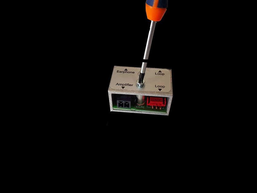
DCL20-E | Manuel d’installation et d’utilisation | Installation and user manual | 2
DCL20-E | Manuel d’installation et d’utilisation | Installation and user manual |                                                       3

                                                          Table des matières

       Table des matières.................................................................................................. 3
       Manuel FR ............................................................................................................ 5
       1. Introduction ......................................................................................................... 6
       1.1 But .................................................................................................................... 6
       1.2 Public visé ........................................................................................................ 6
       1.3 Alerte ............................................................................................................... 6
       1.4 Icônes ............................................................................................................... 6
       1.4.1 Icônes et notes............................................................................................... 6
       1.4.2 Icônes d’attention, d’avertissement et de danger ........................................ 6
       2. Description .......................................................................................................... 7
       2.1 La gamme......................................................................................................... 7
       2.2 Le contenu ....................................................................................................... 7
       2.3 DLC20-E ............................................................................................................ 7
       2.4 Conseils et sécurité .......................................................................................... 8
       3. Installation .......................................................................................................... 9
       4. Connexions et réglages ..................................................................................... 12
       5. Fonctionnement ................................................................................................ 13
       6. Spécifications .................................................................................................... 14
       Manual EN .......................................................................................................... 15
       1. Introduction ....................................................................................................... 16
       1.1 Purpose .......................................................................................................... 16
       1.2 Targeted audience ......................................................................................... 16
       1.3 Alert ............................................................................................................... 16
       1.4 Icons ............................................................................................................... 16
       1.4.1 Icons et notes ............................................................................................... 16
       1.4.2 Attention, warning and danger incons ........................................................ 16
       1.5 Conversion tables .......................................................................................... 17
       2. Description ........................................................................................................ 18
       2.1 The range ....................................................................................................... 18
       2.2 Contents......................................................................................................... 18
       2.3 DLC20-E .......................................................................................................... 18
       2.4 Safety note ..................................................................................................... 19
       3. Installation ........................................................................................................ 20
       4. Connections and settings .................................................................................. 23
       5. Explication ......................................................................................................... 24
       6. Specifications .................................................................................................... 25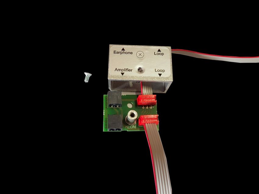
DCL20-E | Manuel d’installation et d’utilisation | Installation and user manual | 4
Français
Amplificateur de boucle à induction magnétique

              Kit– Amplificateur de proximité

                           FR    Manuel d’installation et d’utilisation
                                 DCL20-E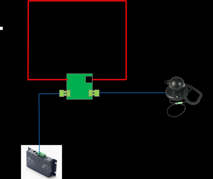
DCL20-E | Manuel d’installation et d’utilisation | Installation and user manual | 6
1. Introduction 1.4 Icônes
1.1 But 1.4.1 Icônes et notes
Le manuel d’installation et d’utilisation fournit Les icônes utilisées avec les notes fournissent
les informations nécessaires pour installer, con- un complément d'informations sur la note. Voir
figurer et utiliser un kit DLC20-K. les exemples suivants :
1.2 Public visé
Note:
Icone Générale des notes
Le manuel d’installation et d’utilisation est des-
tiné aux installateurs et aux utilisateurs du kit
DLC20-K.
1.3 Alertes Note:
Symbole renvoyant à la source
d’information indiquée.
Ce manuel évoque quatre types d’alertes.
Le type d’alerte est lié étroitement à l’effet sus-
ceptible de se produire en cas de non-
observance de l’alerte. Ces alertes, classées
dans l’ordre croissant de gravité, sont les sui-
vantes :
1.4.2 Icônes d’attention, d’avertisse-
ment et de danger
Note
Information complémentaire. Généralement, la Les icônes utilisées en combinaison avec Atten-
nonobservance d’une alerte de type Remarque tion, Avertissement et Danger indiquent le type
n’entraîne pas de dommage matériel ou corpo- de risque présent. Voir les exemples suivants :
rel.
• Attention
La non-observance d’une alerte de type atten- Attention, avertissement, danger:
tion peut entraîner des dommages matériels. Icône générale des avis de prudence, des
avertissements et des dangers.
• Avertissement
La non-observance d’une alerte de type
avertissement peut entraîner des dommages
matériels et corporels graves. Attention, avertissement, danger:
Icône risque d’électrocution.
• Danger
La non-observance d’une alerte du type danger
peut entraîner la mort.
Attention, avertissement, danger:
Icône de risque de décharge électrosta-
tique.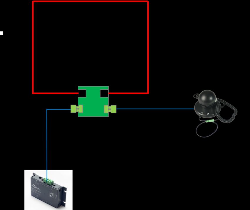
DCL20-E | Manuel d’installation et d’utilisation | Installation and user manual | 7
2. Description
2.3 DLC20-E
Equipement de choix pour les guichets, comp-
toirs ou banques d’accueil, le kit DLC20-K est un
kit d’accessibilité audio permettant la communi- Le DCL20-E est un kit de boucle à induction qui
cation aux personnes malentendantes. Ce pro- permet d’équiper les guichets, banques d’ac-
duit est à destination de tous Etablissements cueils ou comptoirs. Le système permet de ré-
Recevant du Public. Il a l’avantage d’être un des pondre aux restrictions de la loi d’égalité des
plus compact du marché et donc de s’intégrer chances tout en respectant les exigences de la
en toute discrétion pour un résultat optimal. Il norme EN60118-4. L’ensemble est conçu pour
offre surtout une installation pérenne. offrir l’accessibilité aux personnes malenten-
dantes équipées d’un appareil auditif avec la
position T et aux personnes non appareillées
2.1 La gamme
grâce au micro OP-E.
Nous avons le plaisir de vous présenter notre
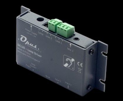
nouvelle marque Opus Technologies conçue et L‘amplificateur est conçu pour être fixé discrète-
fabriquée en France. Nous proposons des pro- ment sous un bureau ou un comptoir. Il est
duits de nouvelles technologies offrant un con- équipé de deux entrées, de réglages et de LED
fort maximum pour les utilisateurs. indiquant la présence de l'alimentation et du
courant de boucle.
L'appareil intègre un traitement audio per-
2.2 Le contenu
mettant d'avoir un asservissement automatique
des niveaux de prise de son, évitant des bruits
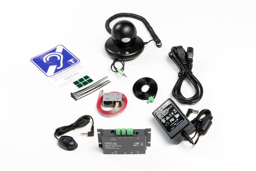
Ce kit comprends :
forts et soudains.
Un amplificateur DLC20
Une alimentation
Un cordon d’alimentation
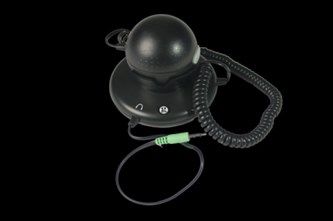
Un micro-surface
Un câble boucle de 1,80m
Trois connecteurs 2 points
Un connecteur 3 points
Lot de 2 autocollants « espaces
adaptés aux malentendants ».
DCL20-E | Manuel d’installation et d’utilisation | Installation and user manual |   8

2.4 Conseils et sécurité

La majorité des problèmes avec la boucle à in-
duction magnétique (BIM) arrive quand l’instal-
lation n’a pas été correctement réfléchie donc
prenons un peu de temps avant de commencer
l’installation et gagnons en résultat et en temps.

Idéalement, l’amplificateur de boucle devra être
placé prés de la zone à couvrir. Ceci peut impli-
quer le placement de l’amplificateur sur un pan-
neau, sous un bureau ou sous un table de salle.

Le microphone de prise de son devra être le
plus prés possible de l’entrée de l’amplificateur.

Pour positionner la boucle dans l’espace à équi-
per, il est important de prendre en compte les
futurs utilisateurs du système.

Par exemple, si vous devez seulement prévoir
l’orateur et le client, une boucle autour du bu-
reau peut être une meilleure solution plutôt
qu’une boucle autour du périmètre de la pièce.
Il limitera le rayonnement et augmentera la
confidentialité.
DCL20-E | Manuel d’installation et d’utilisation | Installation and user manual | 9
3. Installation
Note:
Le fil fournit dans le kit DLC20-K
permet de garantir l’installation rapide
d’un système de boucle magnétique
dans un comptoir d’accueil, guichet ou caisse han-
dicapée.
Afin d’optimiser au mieux le rayonnement du
champ magnétique et pour garantir un meilleur
résultat, le fil devra être placée le plus près du
client.
Connecter ensuite le câble de liaison de 50-70
3.1 Composition et montage de la cm fournit sur le connecteur « amplifier » de
boucle. l’adaptateur et sur le bornier « Loop » de
l’amplificateur.
La boucle est composée des 3 éléments sui-
vants: un câble boucle, d’un connecteur de Votre boucle est maintenant créée et connec-
boucle et d’un cordon de liaison. tée.
La boucle est fournit monté mais il est possible 3.2 Installation de la boucle dans le
de la démonter pour l’adapter à la banque d’ac- comptoir.
cueil. Voir ci-après.
Il existe 3 possibilités de placement d’une
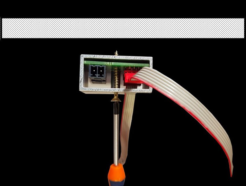
Pour démonter la boucle qui permettra d’équi- boucle dans un comptoir comme décrit ci-
per le comptoir, commencez par dévisser le sup- dessous, cependant nous vous conseillons forte-
port de la carte électronique. ment d’utiliser la première version:
1. Placez la boucle sur la partie verticale et hori-
zontale du comptoir comme indiqué sur la fi-
gure 1. Ce type d’installation permet de garantir
une meilleure couverture devant le guichet.
Boucle
amplificateur
Connectez le tenant et l’aboutissant du câble
boucle sur la carte électronique (connecteur Figure 1.
rouge).
DCL20-E | Manuel d’installation et d’utilisation | Installation and user manual |                        10
                                         amplificateur

                                                         Pour une plus grande couverture autour du
                       Boucle 2                          comptoir, il est possible d’installer un câble au
                                                         sol. La boucle peut-être placée dans la dalle
                      Boucle 1                           (sous le treillis métallique), sous un revêtement
                                                         (parquet, moquette, ...etc) à l’aide d’un ruban
                                                         de cuivre ou collée sous un tapis de sol comme
                                                         illustré figure 3.

                                          Figure 2.             Boucle                                   amplificateur

 2. Positionnez la boucle sur la partie horizontale
 du comptoir en positionnant le câble au plus
 proche du client.

 3. Installez la boucle sur la partie verticale du
 comptoir en positionnant le câble au plus
 proche du client.

 Fixez la boucle à l’aide des clips de fixation pré-
 vus à cet effet. Pour une meilleure durabilité, il
 peut convenir d’installer la boucle dans une
 goulotte plastique.
 Connectez ensuite le cordon de liaison sur le
 bornier du connecteur « amplifier » au bornier
 de l’amplificateur « loop ».
                                                                                                   Figure 3.
 Vissez le connecteur au niveau de la croix.
                                                         Le fil fournit dans le kit DCL20-E produit un
                                                         champ magnétique rayonnant sur un périmètre
                                                         de 1,2m ce qui permet à une personne de rece-
                                                         voir le signal confortablement.

                                                         Le pictogramme avec boucle intégrée permet
                                                         d’être fixé sur l’accueil et de positionner la
                                                         boucle côté client pour éviter les perturbations
                                                         dû au métal (voir figure 4).

                                                                                          Boucle
                                                                                                       amplificateur

             Attention, avertissement, danger:
               La boucle ne doit pas être posi-
             tionnée sous une structure métal-
             lique type caisse de magasin. Le
 champ magnétique serait absorbé par la masse
 métallique et ne permettrait pas d’équiper le
 comptoir convenablement. Il existe d’autres so-
 lutions pour l’installation d’une boucle dans un
                                                                                                   Figure 4.
 comptoir métallique (voir figure 3)
DCL20-E | Manuel d’installation et d’utilisation | Installation and user manual | 11 3.3 Installation de l’écouteur OP-E
DCL20-E | Manuel d’installation et d’utilisation | Installation and user manual |                           12

 4. Connexions et réglages
                                                             4.2 Connexion de la boucle et de l’ali-
                                                             mentation
 4.1 Connexion audio
                                                             Connectez le câble de la boucle sur l’entrée
                   Ligne / Masse
                                   Micro / Ligne /   Masse
                                                             « Loop » du DCL20.

                                                                                    Note:
                                                                             L’entrée boucle n’impose aucun sens
                                       Jack 3,5                              de connexion

                                                             Alimentation: Connectez l’alimentation fournit
                                                             dans le kit sur l’entrée « Power supply »

                                                                Connecteur AC/DC
                                                                   5 x 2,1 mm

 Pour connecter le micro fournit avec le kit, insé-
 rez la prise jack 3,5 dans l’entrée micro 1.

 Connexion à un interphone ou une source spéci-
 fique: Connectez votre source sur l’entrée 2 du
 DCL20. Cette entrée accepte les sources sui-
 vantes: ligne, basse impédance et 100V avec un
 adaptateur.

 Entrée micro 1:
 Type : Jack 3,5
 Caractéristique: alimentation fantôme

 Entrée ligne 1:
 Type: Bornier
 Type d’entrée: Ligne ou micro, connexion à vis.

 Entrée 2:
 Type: Bornier
 Type d’entrée: Ligne/ basse impédance / 100V
 avec un adaptateur.
DCL20-E | Manuel d’installation et d’utilisation | Installation and user manual | 13 5. Fonctionnement Le tenant et l’aboutissant du fil formant la boucle sont reliés à un amplificateur audio. La prothèse auditive dispose d’une bobine appelée souvent « T » ou « T-coil » qui est placée à l’intérieur de la prothèse et qui est constituée d’un fil formant des spires. Le champ magné- tique généré par la grande boucle va traverser les petites boucles dans la prothèse et, par le principe d’induction, le signal électrique présent dans la grande boucle va se retrouver dans les petites. On transmet ainsi le signe de l’amplifi- cateur audio à la prothèse, qui va ensuite le res- tituer à l’oreille de la personne malentendante. La boucle peut être installée au niveau du sol ou du plafond, plus précisément entre 1,10m et 2,20m de la hauteur d’écoute (oreilles). La présence d’une boucle auditive est souvent signalée par un logo bleu représentant une oreille barrée et une lettre T. Généralement, une prothèse auditive dispose de deux positions majeures, la M et la T. La position M permet de percevoir le son grâce à la pression acoustique comme un microphone, tandis que la position T (T pour téléphone) reçoit directement les si- gnaux audio transmis par induction via la bobine intégrée. Certaines prothèses combinent ces deux modes de fonctionnement par la position MT. Elle permet aux malentendants de perce- voir à la fois les bruits ambiants et les signaux transmis par induction.
DCL20-E | Manuel d’installation et d’utilisation | Installation and user manual |                         14

 6. Spécifications

Entrées                                              Dimensions et poids (en
                                                     mm)
Entrée audio           2 (1 entrée micro ou ligne    DCL20                     92 x 52 x 18 (L x H x P)
                       et 1 entrée ligne)

                                                     Emballage                 190 x 190 x 50
Type                   Micro Jack 3,5, bornier
                       Phoenix
                                                     Poids                     0.350g
Fantôme                4,5V 1mA

Alimentation

Caractéristiques       12V DC 1,5A

Type                   Boitier d’alimentation
                       séparé
Voltage                230V 50/60 Hz

Puissance              20W max

Fusible                Thermique

Processeur Audio

Compresseur            Variable 1 : 1 à 20 : 1

Attaque                10mS

Descente               Automatique 500mS ou
                       1500mS
Réduction du bruit     Limites de bande passante
                       pour 8 KHz au gain total,
                       16KHz à –6dB
Dynamique              > 60dB

THD                    THD+N
Hearing loop amplifier
English
Kit– Proximity amplifier
Installation and user manual
EN DCL20-EDCL20-E | Manuel d’installation et d’utilisation | Installation and user manual | 16
1. Introduction
1.4 Icons
1.1 Purpose
1.4.1 Icons and notes
The Installation and Operation Manual provides Icons used with notes provide additional infor-
the necessary information for installing, configu- mation about it. See the following examples:
ring and using an DCL10-K kit.
1.2 Targeted audience
Note:
General icon of notes
The Installation and Operation Manual is in-
tended for installers and users of the DCL20-E
kit.
1.3 Alerts Note:
Symbol referring to the source
indicated information.
This manual discusses four types of alerts.
The type of alert is closely related to the effect
that may occur if the alert is not observed.
These alerts, ranked in ascending order of seve-
rity, are the following: 1.4.2 Attention, warning and danger
icons
• Note
Additional information. Generally, the non- The icons used in combination with Attention,
observance of a Note type alert does not result Warning and Danger indicate the type of risk
in any material or bodily injury. present. See the following examples:
• Attention
Failure to observe a caution alert may result in
property damage. Attention, warning, danger:
the general icon of precautionary state-
• Warning ments,
Non-compliance with a type alert Warning may
result in serious personal injury and property
damage.
• Danger Attention, warning, danger:
Failure to observe a danger alert may result in Electrocution risk icon.
death.
Attention, warning, danger:
Electrostatic discharge risk icon.DCL20-E | Manuel d’installation et d’utilisation | Installation and user manual | 17
1.5 Conversion tables
In this manual, SI units are used to express leng-
ths, masses, temperatures etc.
These can be converted to non-metric units
using the following information.
Table 1: lenght units conversion
25,40 mm = 25,4 mm 1 mm = 1,00000
25,40 mm = 2,54 cm 1 cm = 0,3937 po
30,48 cm = 0,3048 m 1 m = 3,281 pd
1 ml = 1,609 km 1 km = 0,622 ml
Table 2: Mass units conversion
1 lb = 0,4536 kg 1 kg = 2,2046 lb
Table 3: Pressure units conversion
1 psi = 68,95 hPa 1 hPa = 0,0145 psi
Table 4: temperature units conversion
° F = 9 /5. ( ° C + 32 ° C = 5 /9. ( ° F 32)
Note:
1 hPa = 1 mbarDCL20-E | Manuel d’installation et d’utilisation | Installation and user manual | 18
2. Description
2.3 DCL20-E
The DLC20-K kit is the ideal equipment for coun-
The DCL20-E is an induction loop kit that can be
ters or reception desks allowing audio accessibi-
used to equip counters or reception desks. The
lity for people with hearing loss. This product is
system allows to meet the restrictions of the
for all Public-facing establishment. It has the
law of european equal treatment directives while
advantage of being one of the most compact
respecting the requirements of EN60118-4. The
and discreet of the market allowing optimal
set is designed to offer accessibility to hearing-
integration results. It offers especially a peren-
impaired equipped with a T-position on their
nial installation.
hearing aid or for someone without aid with OP-
E microphone.
2.1 The range The amplifier is designed to be discreetly
attached under a desk or counter. It is equipped
We are pleased to introduce our new brand with two inputs, settings and LEDs indicating the
Opus Technologies designed and manufactured presence of power supply and loop current.
in France. We propose innovative products offe-
ring maximum comfort for the users. The device incorporates an audio processing to
have an automatic control of the sound levels,
2.2 Contents avoiding loud and sudden noises.
This kit includes:
A DLC20 amplifier
A power supply
A power cord
A surface micro
A 1,80m loop cable
Three 2-point connectors
One 3-point connectors
A set of 2 stickers « space adapted
for hearing impaired ».DCL20-E | Manuel d’installation et d’utilisation | Installation and user manual | 19 2.4 Safety notes The majority of problems with the hearing loop loop happens when the installation has not been properly reflected so let's take a while be- fore starting the installation to better results and time saving. Ideally, the loop amplifier should be placed near the area to be covered. This may involve placing the amplifier on a panel, under a desk or under a table. The pickup microphone should be as close as possible to the input of the amplifier. To position the loop in the space to be equipped, it is important to take into account the final users of the system. For example, if the place is planned for a con- versation between a speaker and a client, a loop around the desk may be a better solution rather than a loop around the perimeter of the room. It will limit radiation and increase confidentiali- ty.
DCL20-E | Manuel d’installation et d’utilisation | Installation and user manual |                            20

 3. Installation

                   Note:
                 The wire supplied in the DLC20-K
            kit ensures the quick installation of a
            magnetic loop system in a reception
desk, counter or cash desk.
In order to optimize the radiation of the magnetic
field and to guarantee a better result, the wire
should be placed close to the customer.

 3.1 Composition and assembly of the
                                                        Then plug the 50-70 cm connecting cable sup-
 loop                                                   plied to the "amplifier" connector of the adap-
                                                        ter and to the "Loop" terminal block of the am-
 The loop consists on the following 3 elements: a       plifier.
 loop cable, a loop adapter and a connecting
 cable.                                                 Your loop is now created and connected.

 The loop is ready but it is possible to disas-
                                                        3.2 Installation of the loop in the coun-
 semble it to adapt it to the reception desk. See
 below.                                                 ter

 To disassemble the loop that will equip the            1. There are 2 possibilities to place a loop in a
 counter, first unscrew the support of the elec-        counter as described below, however we
 tronic card.                                           strongly advise you to use the first version:Place
                                                        the loop on the vertical and horizontal portion
                                                        of the counter as shown in figure 1. This type of
                                                        installation ensures better coverage in front of
                                                        the counter.
                                                                                      Loop
                                                                                                 amplifier

 Connect the beginning and the end of the loop
 cable to the circuit board (red connector).

                                                                                                 Figure 1.
DCL20-E | Manuel d’installation et d’utilisation | Installation and user manual | 21
amplifier
For greater coverage around the counter, it is
possible to install a cable on the floor. The loop
Loop 1 can be placed in the slab (over the wire mesh),
under a coating (parquet, carpet, ... etc) using a
Loop 2 copper tape or glued under a carpet as shown in
figure 3 .
Loop amplifier
Figure 2.
2. Position the loop on the horizontal counter-
top by positionning the cable closest to the cus-
tomer.
3. Install the loop on the vertical countertop by
positioning the cable closest to the customer.
Set the loop using the binding clips supplied for
this purpose. For better durability, it may be ap-
propriate to install the loop in a plastic chute.
Figure 3.
Then connect the connecting cable to the termi-
nal block "amplifier" of the connector on the
The wire supplied in the DCL20-E kit produces a
terminal block "loop" of the amplifier.
magnetic field radiating on a perimeter of 1.2m
Screw the connector on the cross.
which allows a people to receive the signal com-
fortably.
The pictogram with an integrated loop can be
fixed on the desk and turned to the customer’s
side to avoid disturbances due to metal (see Fi-
gure 4).
Loop
amplifier
Attention, warning, danger:
The loop must not be positioned
under a metal structure. The ma-
gnetic field would be absorbed by
the metal mass and would not equip
the counter properly. There are
Figure 4.
other solutions for installing a loop in a metal
counter (see figure 3)DCL20-E | Manuel d’installation et d’utilisation | Installation and user manual | 22 3.3 OP-E microphone installation
DCL20-E | Manuel d’installation et d’utilisation | Installation and user manual |                               23

 4. Connections and settings
                                                          4.2 Loop and power connection
 4.1 audio connection                                     Connect the loop cable to the "Loop" input on
                    Ligne / Mass
                                   micro / Ligne / Mass
                                                          the DCL20.

                                                                                      Note:
                                       Jack 3,5
                                                                                Loop input does not impose any sense
                                                                                of connection

                                                          Power supply: Connect the power supply from
                                                          the kit to the "Power supply" input.

                                                            AC / DC connector
                                                               5 x 2,1 mm

 To connect the supplied microphone with the
 kit, insert the 3.5 jack into the microphone input
 1.

 Connecting to an intercom or specific source:
 Connect your source to input 2 of the DCL20.
 This input supports the following sources: line,
 low impedance and 100V with an adapter.

 Micro input 1:
 Type : Jack 3,5
 Feature: phantom power

 Input ligne 1:
 Type: Terminal Block
 Input type: Line or microphone, screw connec-
 tion.

 Input 2:
 Type: Terminal Block
 Input type: Line /low impedance/ 100V with an
 adapter.
DCL20-E | Manuel d’installation et d’utilisation | Installation and user manual | 24 5. Explication The wire forming the loop are connected to an audio amplifier. The hearing aid often called "T" or "T-coil" which is placed inside spirale wire. The magnetic field generated by the large loop will cross the coil and, by the induction process, the electrical signal present in the large loop will be found in the one small. The signal of the au- dio amplifier is transmitted to the hearing aids, which will then restore it to the ear of the im- paired ones. The loop can be installed in the floor or at the roof level, more precisely between 1.10m and 2.20m from the listening height (ears). The presence of an hearing loop is often indi- cated by a blue logo representing a crossed out ear and a letter T. Generally, a hearing aid has two major positions, the M and the T. The posi- tion M makes it possible to perceive the sound thanks to sound pressure as a microphone, while the position T (T for telephone) directly receives the audio signals transmitted by induc- tion via the integrated coil. Some aids combine these two modes of operation with the MT posi- tion. It allows the hearing impaired to perceive both ambient noise and inductively transmitted signals.
DCL20-E | Manuel d’installation et d’utilisation | Installation and user manual |                      25

 6. Specifications

Inputs                                              Dimensions and weight
                                                    (in mm)
Audio inputs           2 (1 microphone or line      DCL20                   92 x 52 x 18 (L x H x P)
                       input and 1 line input)

                                                    Packaging               190 x 190 x 50
Type                   Micro Jack 3.5, Phoenix
                       terminal block
                                                    Weight                  0.350g
Phantom                4,5V 1mA

Power supply

Characteristics        12V DC 1,5A

Type                   Separate power box

Voltage                230V 50/60 Hz

Power                  20W max

Fuse                   Thermal

Audio Processor

Compressor             Variable 1: 1 to 20: 1

Attack                 10mS

Descent                Automatic 500mS ou
                       1500mS
Noise reduction        Bandwidth Limits for 8
                       KHz at Total Gain, 16KHz
                       to -6dB
Dynamic                > 60dB

THD                    THD+N
DCL20-E | Manuel d’installation et d’utilisation | Installation and user manual | 26
DCL20-E | Manuel d’installation et d’utilisation | Installation and user manual |   27

 Notes:

  ____________________________________________________________________
  ____________________________________________________________________
  ____________________________________________________________________
  ____________________________________________________________________
  ____________________________________________________________________
  ____________________________________________________________________
  ____________________________________________________________________
  ____________________________________________________________________
  ____________________________________________________________________
  ____________________________________________________________________
  ____________________________________________________________________
  ____________________________________________________________________
  ____________________________________________________________________
  ____________________________________________________________________
  ____________________________________________________________________
  ____________________________________________________________________
  ____________________________________________________________________
  ____________________________________________________________________
  ____________________________________________________________________
  ____________________________________________________________________
  ____________________________________________________________________
  ____________________________________________________________________
  ____________________________________________________________________
  ____________________________________________________________________
  ____________________________________________________________________
  ____________________________________________________________________
  ____________________________________________________________________
  ____________________________________________________________________
  ____________________________________________________________________
  ____________________________________________________________________
  ____________________________________________________________________
  ____________________________________________________________________
  ____________________________________________________________________
  ____________________________________________________________________
  ____________________________________________________________________
  ____________________________________________________________________
  ____________________________________________________________________
  ____________________________________________________________________
  ____________________________________________________________________
Les informations de ce documents sont susceptibles d’être modifiées
Document information is subject to change

Date: 2017/11
| manuel d’installation et d’utilisation | installation and user manual | DCL20-E

                          Pour toutes questions complementaires, contacter nous.
                          For any questions, contact us.

OPUS TECHNOLOGIES — ZI LAGRANGE II — 9 Chemin de la Vieille Ferme — 33650 MARTILLAC
Tel: 09.81.24.00.06. — Fax: 09.82.63.22.56. — contact@opus-technologies.fr
Vous pouvez aussi lire