Lumination LED Luminaires - (EL Option - Emergency Light Supplement) Applicable Luminaire Series: LDS, LOP, LUS, LIS, SS, LDX, LRC, DI - Current by GE
←
→
Transcription du contenu de la page
Si votre navigateur ne rend pas la page correctement, lisez s'il vous plaît le contenu de la page ci-dessous
Installation Guide
                                                                                                IND102 | GE2028-2368

Lumination® LED Luminaires
(EL Option - Emergency Light Supplement)
Applicable Luminaire Series: LDS, LOP, LUS, LIS, SS, LDX, LRC, DI

                BEFORE YOU BEGIN
                Read these instructions completely and carefully.
                Read and follow appropriate Lumination LED Luminaire Installation Guide for fixture installation.

                                  IMPORTANT SAFEGUARDS
              WHEN USING ELECTRICAL EQUIPMENT, BASIC SAFETY PRECAUTIONS
                SHOULD ALWAYS BE FOLLOWED INCLUDING THE FOLLOWING:

               READ AND FOLLOW ALL SAFETY INSTRUCTIONS
1. Turn power off before inspection, installation or removal.
2. To reduce the risk of electric shock, disconnect both normal and emergency power suppliers and converter
    connector of the emergency driver before servicing.
3. The emergency driver must be fed from the same branch circuit as the AC driver.
4. Do not attempt to service the battery. A sealed, no-maintenance battery is used that is not field replaceable.
    Contact the manufacturer for information on service.
5. Follow all NEC and local codes. Properly ground electrical enclosure.
6. Use only UL listed wire for input/output connections. Minimum size 18 AWG (0.75mm2).
7. Equipment should be mounted in locations and at heights where it will not readily be subjected to tampering
    by unauthorized personnel.
8. Do not use outdoors.
9. Do not mount near gas or electric heaters.
10. Do not use this equipment for other than intended use.
11. The use of accessory equipment not recommended by the manufacturer may cause an unsafe condition.

                                 SAVE THESE INSTRUCTIONS
                                                  Ni-Cd Battery
        The rechargeable Nickel-Cadmium battery in this product must be recycled or disposed of properly.

                   This equipment is not self-testing in conformance
                       with the Life Safety Code, ANSI/NFPA 101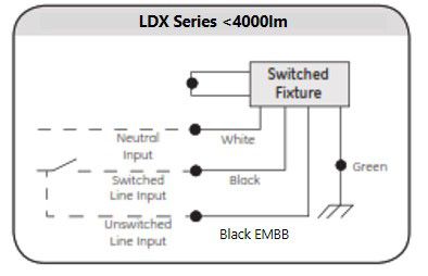
Lumination® LED Luminaires (EL Option)                                                         Installation Guide

                AVANT DE COMMENCER
                Lire attentivement les instructions.
                Lire et suivre la procédure d’installation propre au luminaire à DEL Lumination.

                     CONSIGNES IMPORTANTES DE SÉCURITÉ
                     Lors de l’utilisation d’appareils électriques, des précautions
                      de sécurité élémentaires doivent être suivies, notamment:

                 Lire et suivre toutes les instructions de sécurité
1. Couper l’alimentation avant l’inspection, l’installation ou la mise au rencart.
2. Afin de réduire le risque d’électrocution, débrancher les tensions de secteur et d’urgence,ainsi que le
    connecteur de l’alimentation d’urgence.
3. L’alimentation d’urgence doit être alimentée par le même circuit que l’alimentationprincipale.
4. Ne pas tenter de réparer ou remplacer la batterie. La batterie fournie est scellée, non-réparable et ne doit pas
    être remplacée par l’utilisateur. Contactez le manufacturier pourtoute information concernant le
    remplacement de la batterie.
5. Suivre les codes électriques en vigueur dans votre région. L’enceinte électrique doit êtremise à la terre
    correctement.
6. N’utilisez que des fils reconnus par UL / ACNOR pour les connections d’entrée / sortie. Lasection minimale
    des fils doit être 0.75 mm2 (calibre 18 AWG).
7. Cet appareil doit être installé dans un endroit et à une hauteur ne permettant pas samanipulation par des
    personnes non-autorisées.
8. Ne pas utiliser à l’extérieur.
9. Ne pas installer à proximité d’appareils de chauffage électriques ou à gaz.
10. Ne pas utiliser cet appareil hors de son usage désigné.
11. L’utilisation d’accessoires non recommandés par le manufacturier peut causer desconditions non sécuritaires.

                                   Conservez ces instructions
                                                   Batterie Ni-Cd
 La batterie rechargeable nickel-cadmium de ce produit doit être recyclée ou mise au rencart de façon adéquate.

         Cet appareil n’effectue pas d’auto diagnostique, en conformité
          avec le code de la sécurité des personnes (ANSI/NFPA 101)

                                                         2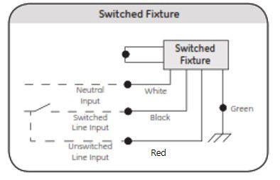
Lumination® LED Luminaires (EL Option) Installation Guide
Luminaire Installation Electrical Connections
Follow Appropriate Lumination LED Luminaire Installations Instructions to install the fixture and access the electrical
compartment if required. Take standard precautions against static discharge during fixture installation.
IMPORTANT: “EL” and “E2” Emergency Battery Backup fixture option has increased
weight. Ensure proper fixture support means are used.
NOTE: As received from the manufacturer, the luminaire may be partially energized.
EMBB equipped luminaires provide emergency egress lighting during interruptions of normal building power. Typical in-
stallations will require an unswitched power line in addition to the standard line to provide the EMBB system with a signal
that the building power has been interrupted. For luminaires intended to run as “always-on” nightlights only one power
drop is required and the switched and unswitched inputs to the battery system may be wired together in the luminaire. In
all cases switched and unswitched lines MUST originate from the same electrical panel.
For LDS, LOP and SS Series Luminaires with “EL” or “E2” Option
LDS, LOP and SS series luminaires are provided with an additional
red conductor which can be used to provide the unswitched line
to the EMBB units in a continuous row. When EMBB luminaires
are in a continuous row the red conductor must not be used for
any other purpose.
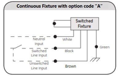
For LIS and LUS Series Luminaires with “EL” or “E2” Option
LIS and LUS series luminaires may be provided with an optional
branch circuit (option code “BC” for LUS or option code “A” for LIS)
which may be used to provide the unswitched line in continuous runs.
If this option is not used then unswitched lines must be dropped
individually to each luminaire in the run following the wiring diagram
of the independent fixture.
For both continuous and independent luminaires the unswitched
connection to the battery is left unfinished so that the correct
conductor can be chosen in the field as appropriate. In each EMBB
luminaire the red conductor from the battery unit should be
connected to either the brown continuous wire or the individual
unswitched line drop.
3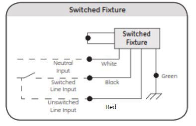
Lumination® LED Luminaires (EL Option)                                                         Installation Guide

For LRC Series Luminaires with “EL” Option
LRC Series luminaires with “EL” option are equipped with a secondary battery enclosure equipped with a remote test
switch and connected to the primary driver enclosure with a quick disconnect box. All supply wiring connections to the
luminaire system are made in the primary enclosure. The switched line and common neutral are connected to the Line
Filter inputs and the unswitched line to the battery input.

For 120V LRC luminaires the TPC input is black and for 277V LRC luminaires the TPC input is red. To ensure proper
operation of EMBB system confirm that system voltage matches line voltage.

For LDX Series and DI Series Luminaires with “EL” Option up to 3000lm

LDX Series luminaires with “EL” option and with light levels
3000lm and below are equipped with a battery system integrated
into the electrical enclosure. The switched line must be
connected to the black conductor leading to the
knockout-mounted TPC and the unswitched line must be
connected to the black conductor leading to the EMBB system
control box

                                                           4
Lumination® LED Luminaires (EL Option) Installation Guide
For Fixtures with a Remote Test Switch: Indicator Test Switch
Installation
1 Important: Fixtures without an integral indicator test switch must
be installed with a factory-provided remote mount indicator test
switch (ITS). Follow National Electrical Code (NEC) and local code
regulations when installing the ITS.
2 Choose a suitable location in a wall or the ceiling for the ITS.
Maximum remote mounting distance for the ITS is 50 feet. Install
a UL listed single-gang electrical box.
3 Using UL listed wire, minimum size 18 AWG, minimum 75°C rating,
and UL listed electrical conduit, connect the leads on the ITS.
Provide enough wire to reach the lighting fixture electrical
enclosure. Use 18-14AWG twist-on wire connectors.
Recommended: use one violet and one brown wire to match the leads on the ITS.
4 Remove one knockout from the single-gang electrical box. Using UL listed conduit, run wire from the ITS to the lighting fixture
electrical enclosure.
5 Close the single-gang electrical box using the factory-provided wall plate cover and hardware.
Optional Installation: Dimming or Control Interface
Follow instructions from appropriate Lumination LED Luminaire Installation Instructions to install optional control interfaces.
Note: The fixture will not be controllable during emergency operation.
Note: CONTACT FACTORY for details and limitations when seeking to incorporate this product with an emergency system
other than Battery Backup.
Emergency Lighting Fixture Operation
The emergency driver is capable of operating the LED load for a minimum of 90 minutes. The emergency driver battery re-
charge time is 24 hours. After installation, the battery should be allowed to charge.
This emergency lighting fixture should be tested regularly according to national and local code requirements. To test the
emergency driver, remove AC power or press and hold the indicator test switch. Take standard precautions against static
discharge while operating indicator test switch.
www.gecurrent.com
© 2020 Current Lighting Solutions, LLC. All rights reserved. GE and the GE monogram are trademarks of the
General Electric Company and are used under license. Information provided is subject to change without
notice. All values are design or typical values when measured under laboratory conditions.
IND102 (Rev 04/28/20) Enovia - GE2028-2368 Rev 03Vous pouvez aussi lire